Modine: Installation And Service Manual - Alpine Home Air Products
Modine: Installation And Service Manual - Alpine Home Air Products
Modine: Installation And Service Manual - Alpine Home Air Products

Create successful ePaper yourself
Turn your PDF publications into a flip-book with our unique Google optimized e-Paper software.
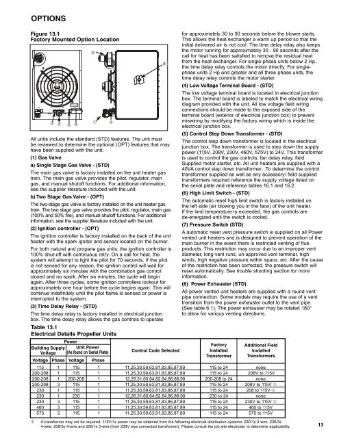
OPTIONSFigure 13.1Factory Mounted Option Location➁➆➄➂➇➀All units include the standard (STD) features. The unit mustbe reviewed to determine the optional (OPT) features that mayhave been supplied with the unit.(1) Gas Valvea) Single Stage Gas Valve - (STD)The main gas valve is factory installed on the unit heater gastrain. The main gas valve provides the pilot, regulator, maingas, and manual shutoff functions. For additional information,see the supplier literature included with the unit.b) Two Stage Gas Valve - (OPT)The two-stage gas valve is factory installed on the unit heater gastrain. The two stage gas valve provides the pilot, regulator, main gas(100% and 50% fire), and manual shutoff functions. For additionalinformation, see the supplier literature included with the unit.(2) Ignition controller - (OPT)The ignition controller is factory installed on the back of the unitheater with the spark igniter and sensor located on the burner.For both natural and propane gas units, the ignition controller is100% shut-off with continuous retry. On a call for heat, thesystem will attempt to light the pilot for 70 seconds. If the pilotis not sensed for any reason, the ignition control will wait forapproximately six minutes with the combination gas controlclosed and no spark. After six minutes, the cycle will beginagain. After three cycles, some ignition controllers lockout forapproximately one hour before the cycle begins again. This willcontinue indefinitely until the pilot flame is sensed or power isinterrupted to the system.(3) Time Delay Relay - (STD)The time delay relay is factory installed in electrical junctionbox. The time delay relay allows the gas controls to operateTable 13.1Electrical Details Propeller UnitsPowerBuilding Supply Unit PowerVoltage (As found on Serial Plate)Control Code SelectedVoltage Phase Voltage Phase➃6for approximately 30 to 90 seconds before the blower starts.This allows the heat exchanger a warm up period so that theinitial delivered air is not cool. The time delay relay also keepsthe motor running for approximately 30 - 90 seconds after thecall for heat has been satisfied to remove the residual heatfrom the heat exchanger. For single-phase units below 2 Hp,the time delay relay controls the motor directly. For singlephaseunits 2 Hp and greater and all three phase units, thetime delay relay controls the motor starter.(4) Low Voltage Terminal Board - (STD)The low voltage terminal board is located in electrical junctionbox. The terminal board is labeled to match the electrical wiringdiagram provided with the unit. All low voltage field wiringconnections should be made to the exposed side of theterminal board (exterior of electrical junction box) to preventmiswiring by modifying the factory wiring which is inside theelectrical junction box.(5) Control Step Down Transformer - (STD)The control step down transformer is located in the electricaljunction box. The transformer is used to step down the supplypower (115V, 208V, 230V, 460V, 575V) to 24V. This transformeris used to control the gas controls, fan delay relay, fieldSupplied motor starter, etc. All unit heaters are supplied with a40VA control step down transformer. To determine the controltransformer supplied as well as any accessory/ field suppliedtransformers required reference the supply voltage listed onthe serial plate and reference tables 16.1 and 16.2.(6) High Limit Switch - (STD)The automatic reset high limit switch is factory installed onthe left side (air blowing you in the face) of the unit heater.If the limit temperature is exceeded, the gas controls arede-energized until the switch is cooled.(7) Pressure Switch (STD)A automatic reset vent pressure switch is supplied on all Powervented unit heaters and is designed to prevent operation of themain burner in the event there is restricted venting of flueproducts. This restriction may occur due to an improper ventdiameter, long vent runs, un-approved vent terminal, highwinds, high negative pressure within space, etc. After the causeof the restriction has been corrected, the pressure switch willreset automatically. See trouble shooting section for moreinformation.(8) Power Exhauster (STD)All power vented unit heaters are supplied with a round ventpipe connection. Some models may require the use of a venttransition from the power exhauster outlet to the vent pipe(See table 6.1). The power exhauster may be rotated 180°to allow for various venting directions.FactoryInstalledTransformerAdditional FieldInstalledTransformers115 1 115 1 11,25,30,59,63,81,83,85,87,89 115 to 24 none200-208 1 115 1 11,25,30,59,63,81,83,85,87,89 115 to 24 208V to 115V200-208 1 200-208 1 12,26,31,60,64,82,84,86,88,90 200-208 to 24 none200-208 3 115 1 11,25,30,59,63,81,83,85,87,89 115 to 24 208V to 115V ➀230 1 115 1 11,25,30,59,63,81,83,85,87,89 115 to 24 208 to 115V ➀230 1 230 1 12,26,31,60,64,82,84,86,88,90 230 to 24 none230 3 115 1 11,25,30,59,63,81,83,85,87,89 115 to 24 230V to 115V ➀460 3 115 1 11,25,30,59,63,81,83,85,87,89 115 to 24 460 to 115V575 3 115 1 11,25,30,59,63,81,83,85,87,89 115 to 24 575 to 115V➀ A transformer may not be required. 115V/1φ power may be obtained from the following electrical distribution systems: 230/1φ 3-wire, 230/3φ4-wire, 208/3φ 4-wire and 208/1φ 3-wire (from 208V wye connected transformer). Please consult the job site electrician to determine applicability.13

![Owner's Manual (General) [pdf] - Appliance Factory Parts](https://img.yumpu.com/50830858/1/184x260/owners-manual-general-pdf-appliance-factory-parts.jpg?quality=85)