Modine: Installation And Service Manual - Alpine Home Air Products
Modine: Installation And Service Manual - Alpine Home Air Products
Modine: Installation And Service Manual - Alpine Home Air Products

Create successful ePaper yourself
Turn your PDF publications into a flip-book with our unique Google optimized e-Paper software.
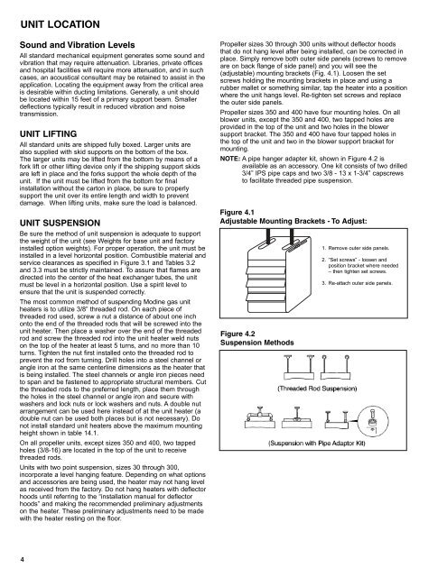
UNIT LOCATIONSound and Vibration LevelsAll standard mechanical equipment generates some sound andvibration that may require attenuation. Libraries, private officesand hospital facilities will require more attenuation, and in suchcases, an acoustical consultant may be retained to assist in theapplication. Locating the equipment away from the critical areais desirable within ducting limitations. Generally, a unit shouldbe located within 15 feet of a primary support beam. Smallerdeflections typically result in reduced vibration and noisetransmission.UNIT LIFTINGAll standard units are shipped fully boxed. Larger units arealso supplied with skid supports on the bottom of the box.The larger units may be lifted from the bottom by means of afork lift or other lifting device only if the shipping support skidsare left in place and the forks support the whole depth of theunit. If the unit must be lifted from the bottom for finalinstallation without the carton in place, be sure to properlysupport the unit over its entire length and width to preventdamage. When lifting units, make sure the load is balanced.UNIT SUSPENSIONBe sure the method of unit suspension is adequate to supportthe weight of the unit (see Weights for base unit and factoryinstalled option weights). For proper operation, the unit must beinstalled in a level horizontal position. Combustible material andservice clearances as specified in Figure 3.1 and Tables 3.2and 3.3 must be strictly maintained. To assure that flames aredirected into the center of the heat exchanger tubes, the unitmust be level in a horizontal position. Use a spirit level toensure that the unit is suspended correctly.The most common method of suspending <strong>Modine</strong> gas unitheaters is to utilize 3/8” threaded rod. On each piece ofthreaded rod used, screw a nut a distance of about one inchonto the end of the threaded rods that will be screwed into theunit heater. Then place a washer over the end of the threadedrod and screw the threaded rod into the unit heater weld nutson the top of the heater at least 5 turns, and no more than 10turns. Tighten the nut first installed onto the threaded rod toprevent the rod from turning. Drill holes into a steel channel orangle iron at the same centerline dimensions as the heater thatis being installed. The steel channels or angle iron pieces needto span and be fastened to appropriate structural members. Cutthe threaded rods to the preferred length, place them throughthe holes in the steel channel or angle iron and secure withwashers and lock nuts or lock washers and nuts. A double nutarrangement can be used here instead of at the unit heater (adouble nut can be used both places but is not necessary). Donot install standard unit heaters above the maximum mountingheight shown in table 14.1.On all propeller units, except sizes 350 and 400, two tappedholes (3/8-16) are located in the top of the unit to receivethreaded rods.Units with two point suspension, sizes 30 through 300,incorporate a level hanging feature. Depending on what optionsand accessories are being used, the heater may not hang levelas received from the factory. Do not hang heaters with deflectorhoods until referring to the “installation manual for deflectorhoods” and making the recommended preliminary adjustmentson the heater. These preliminary adjustments need to be madewith the heater resting on the floor.Propeller sizes 30 through 300 units without deflector hoodsthat do not hang level after being installed, can be corrected inplace. Simply remove both outer side panels (screws to removeare on back flange of side panel) and you will see the(adjustable) mounting brackets (Fig. 4.1). Loosen the setscrews holding the mounting brackets in place and using arubber mallet or something similar, tap the heater into a positionwhere the unit hangs level. Re-tighten set screws and replacethe outer side panels.Propeller sizes 350 and 400 have four mounting holes. On allblower units, except the 350 and 400, two tapped holes areprovided in the top of the unit and two holes in the blowersupport bracket. The 350 and 400 have four tapped holes inthe top of the unit and two in the blower support bracket formounting.NOTE: A pipe hanger adapter kit, shown in Figure 4.2 isavailable as an accessory. One kit consists of two drilled3/4” IPS pipe caps and two 3/8 - 13 x 1-3/4” capscrewsto facilitate threaded pipe suspension.Figure 4.1Adjustable Mounting Brackets - To Adjust:Figure 4.2Suspension Methods1. Remove outer side panels.2. “Set screws” - loosen andposition bracket where needed– then tighten set screws.3. Re-attach outer side panels.4

![Owner's Manual (General) [pdf] - Appliance Factory Parts](https://img.yumpu.com/50830858/1/184x260/owners-manual-general-pdf-appliance-factory-parts.jpg?quality=85)