GENERAL PERFORMANCE DATATable 14.1 - Performance — Propeller Models ➀ ➁StandardModel NumberPDP 30 PDP 50 PDP 75 PDP 100 PDP 125 PDP 150 PDP 175 PDP 200 PDP 250 PDP 300 PDP 350 PDP 400Btu/Hr. Input 30,000 50,000 75,000 100,000 125,000 150,000 175,000 200,000 250,000 300,000 350,000 400,000Btu/Hr. Output 24,000 40,000 60,000 80,000 100,000 120,000 140,000 160,000 200,000 240,000 280,000 320,000Entering <strong>Air</strong>flow (CFM) 440 740 1100 1460 1850 2180 2550 2870 3700 4460 4870 5440Outlet Velocity 515 610 736 860 870 931 959 819 1053 1123 1068 1016<strong>Air</strong> Temp. Rise (°F) 51 50 51 51 50 51 51 52 50 50 53 54Max. Mounting Hgt.(Ft) ➂ 7 9 12 14 14 16 17 15 19 21 20 19Heat Throw (Ft) ➂(Max. Mtg. Hgt.) 25 33 41 49 51 55 59 51 67 74 70 69Motor Type SP SP PSC PSC PSC PSC PSC PSC PSC PSC PSC PSC115/60/1 (PC01) 1/40 1/40 1/12 1/12 1/8 1/8 1/6 1/6 1/3 1/2 3/4 3/4HP 230/60/1 (PC02) 1/40 1/40 1/8 1/8 1/8 1/8 1/6 1/6 1/3 1/2 3/4 3/4200-208/60/1 (PC03) 1/40 1/40 1/8 1/8 1/8 1/8 1/6 1/6 1/3 1/2 3/4 3/4Table 14.2 - Motor Data and Total Unit Power Requirements — Propeller Models ➀Unit Voltage 115/60/1 115/60/1 With Use of Transformer 208/60/1 230/60/1Supply Voltage 115/60/1 208V 230V 460V 575V 208/60/1 230/60/1HP Mtr. Mtr. Total Max KVA Total KVA Total KVA Total KVA Total Mtr. Mtr. Total Max Mtr. Mtr. Total MaxAmps Rpm Amps Watts Req. Amps Req. Amps Req. Amps Req. Amps Amps Rpm Amps Watts Amps. RPM Amps Watts1/40 1.0 1550 2.7 320 0.50 2.4 0.50 2.17 0.50 1.09 0.50 0.87 0.4 1550 1.3 270 0.4 1550 1.3 3001/12 1.6 1625 3.3 400 0.50 2.4 0.50 2.17 0.50 1.09 0.50 0.87 --- --- --- --- --- --- --- ---1/8 2.3 1625 4.0 480 0.50 2.4 0.50 2.17 0.50 1.09 0.50 0.87 1.0 1625 1.9 400 1.0 1625 1.9 4401/6 2.7 1075 5.1 610 1.00 4.81 0.75 3.26 0.75 1.63 0.75 1.30 1.5 1075 2.8 580 1.5 1075 2.8 6401/3 5.4 1075 7.7 890 1.00 4.81 1.00 4.35 1.00 2.17 1.00 1.74 --- --- --- --- 2.5 1075 3.7 8401/2 7.5 1075 9.8 1180 1.50 7.2 1.50 6.52 1.50 3.26 1.50 2.61 --- --- --- --- 3.5 1075 4.7 10703/4 8.8 1125 11.1 1330 1.50 7.2 1.50 6.52 1.50 3.26 1.50 2.61 --- --- --- --- 4.4 1125 5.5 1280➀ All motors used are produced, rated and tested by reputable manufacturers in accordance with NEMA standards and carry the standard warranty of both the motormanufacturer and <strong>Modine</strong>. All motors are totally enclosed and all single phase motors have built-in thermal overload protection.➁ Ratings shown are for elevations up to 2,000 ft. For elevations above 2,000 feet, ratings should be reduced at the rate of 4% for each 1,000 feet above sea level.(In Canada see rating plate.) Reduction of ratings requires use of a high altitude kit.➂ Data taken at 55°F air temperature rise. At 65°F ambient and unit fired at full-rated input. Mounting height as measured from bottom of unit, and without deflectorhoods.Table 14.3 - Performance Data - 30°, 60°, and 90° Downward Deflector HoodsHoodType30°60°90°Max. MTG. HGT.XYZMax. MTG. HGT.XYZMax. MTG. HGT.SModel Size50 75 100 125 150 175 200 250 300 350 40012 14 16 18 18 18 18 22 24 24 244 5 5 6 6 9 6 8 8 8 812 14 17 18 20 26 18 24 26 24 2417 21 25 26 29 37 26 35 38 36 3510 14 16 18 18 18 18 22 24 24 240 0 0 0 0 0 0 0 0 0 014 10 13 12 13 23 12 16 19 16 1619 14 19 17 19 32 17 23 28 24 2312 16 20 20 22 22 22 28 30 30 3012 16 19 21 23 25 22 29 32 20 29➁ Data Based on unit fired at full rated input, 60° - 80°F entering air temperature, and a 40°Ftemperature rise through unit. Maximum mounting heights higher versus units without outletdevises.S30 DOWNTURN NOZZLE60 DOWNTURN NOZZLESH30° and 60° THROW-FLOOR COVERAGENOTE:X = FEED FROM HEATERTO START OFFLOOR COVERAGE.Y = FEET TO END OFFLOOR COVERAGE.Z = FEET TO END OFTHROW.MOUNTINGHEIGHT60301430° HOOD 60° HOOD90° HOODX60 NOZZLEXYZ30 NOZZLEYZ
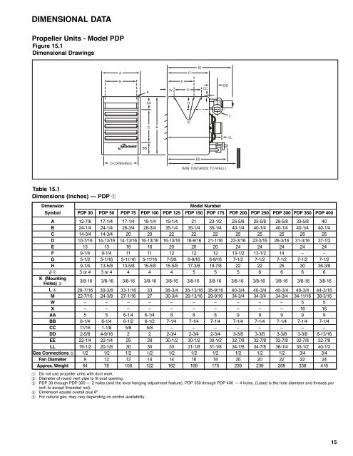
DIMENSIONAL DATAPropeller Units - Model PDPFigure 15.1Dimensional DrawingsACMHKWFXCCDDAAGJEBKLLBBD (OPENING)EEL(MIN. DISTANCE TO WALL)Table 15.1Dimensions (inches) — PDP ➀DimensionModel NumberSymbol PDP 30 PDP 50 PDP 75 PDP 100 PDP 125 PDP 150 PDP 175 PDP 200 PDP 250 PDP 300 PDP 350 PDP 400A 12-7/8 17-1/4 17-1/4 19-1/4 19-1/4 21 23-1/2 25-5/8 25-5/8 28-5/8 33-5/8 40B 24-1/4 24-1/4 28-3/4 28-3/4 35-1/4 35-1/4 35-1/4 40-1/4 40-1/4 40-1/4 40-1/4 40-1/4C 14-3/4 14-3/4 20 20 22 22 22 25 25 25 25 25D 10-7/16 14-13/16 14-13/16 16-13/16 16-13/16 18-9/16 21-1/16 23-3/16 23-3/16 26-3/16 31-3/16 37-1/2E 13 13 16 16 20 20 20 24 24 24 24 24F 9-1/4 9-1/4 11 11 12 12 12 13-1/2 13-1/2 14 – –G 5-1/2 5-1/16 5-11/16 5-11/16 7-5/8 6-9/16 6-9/16 7-1/2 7-1/2 7-1/2 7-1/2 7-1/2H 9-1/4 13-5/8 13-5/8 15-5/8 15-5/8 17-3/8 19-7/8 22 22 25 30 36-3/8J ➁ 3 or 4 3 or 4 4 4 4 5 5 5 6 6 6 6K (MountingHoles) ➂L ➃3/8-1628-7/163/8-1630-3/83/8-1633-1/163/8-16333/8-1636-3/43/8-1635-13/163/8-1635-9/163/8-1640-3/43/8-1640-3/43/8-1640-3/43/8-1640-3/43/8-1644-3/16M 22-7/16 24-3/8 27-1/16 27 30-3/4 29-13/16 29-9/16 34-3/4 34-3/4 34-3/4 34-11/16 38-3/16W – – – – – – – – – – 5 5X – – – – – – – – – – 16 16AA 5 5 6-1/4 6-1/4 8 8 8 9 9 9 9 9BB 6-1/4 6-1/4 6-1/2 6-1/2 7-1/4 7-1/4 7-1/4 7-1/4 7-1/4 7-1/4 7-1/4 7-1/4CC 11/16 1-1/8 5/8 5/8 – – – – – – – –DD 2-5/8 4-9/16 2 2 2-3/4 2-3/4 2-3/4 3-3/8 3-3/8 3-3/8 3-3/8 6-13/16EE 22-1/4 22-1/4 29 29 30-1/2 30-1/2 30-1/2 32-7/8 32-7/8 32-7/8 32-7/8 32-7/8LL 19-1/2 20-1/8 30 30 30 31-1/8 31-1/8 34-7/8 34-7/8 36-1/4 35-1/2 40-1/2Gas Connections ➄ 1/2 1/2 1/2 1/2 1/2 1/2 1/2 1/2 1/2 1/2 3/4 3/4Fan Diameter 9 12 12 14 14 16 18 20 20 22 22 24Approx. Weight 64 78 108 122 162 168 175 239 239 269 338 418➀ Do not use propeller units with duct work.➁ Diameter of round vent pipe to fit oval opening.➂ PDP 30 through PDP 300 — 2 holes (and the level hanging adjustment feature). PDP 350 through PDP 400 — 4 holes. (Listed is the hole diameter and threads perinch to accept threaded rod).➃ Dimension equals overall plus 6".➄ For natural gas; may vary depending on control availability.15


![Owner's Manual (General) [pdf] - Appliance Factory Parts](https://img.yumpu.com/50830858/1/184x260/owners-manual-general-pdf-appliance-factory-parts.jpg?quality=85)