GE Fanuc Automation - Platforma Internetowa ASTOR
GE Fanuc Automation - Platforma Internetowa ASTOR
GE Fanuc Automation - Platforma Internetowa ASTOR

You also want an ePaper? Increase the reach of your titles
YUMPU automatically turns print PDFs into web optimized ePapers that Google loves.
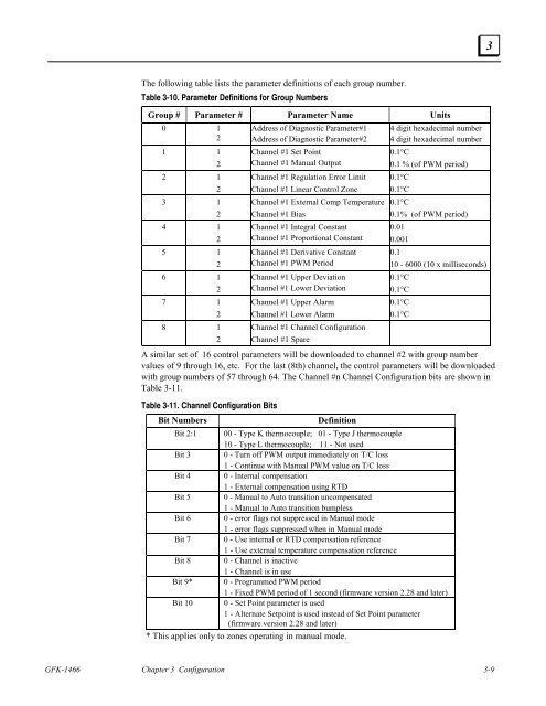
The following table lists the parameter definitions of each group number.<br />
Table 3-10. Parameter Definitions for Group Numbers<br />
Group # Parameter # Parameter Name Units<br />
0 1<br />
2<br />
1 1<br />
2<br />
2 1<br />
2<br />
3 1<br />
2<br />
4 1<br />
2<br />
5 1<br />
2<br />
6 1<br />
2<br />
7 1<br />
2<br />
8 1<br />
2<br />
Address of Diagnostic Parameter#1<br />
Address of Diagnostic Parameter#2<br />
Channel #1 Set Point<br />
Channel #1 Manual Output<br />
Channel #1 Regulation Error Limit<br />
Channel #1 Linear Control Zone<br />
4 digit hexadecimal number<br />
4 digit hexadecimal number<br />
0.1°C<br />
0.1 % (of PWM period)<br />
GFK-1466 Chapter 3 Configuration 3-9<br />
0.1°C<br />
0.1°C<br />
Channel #1 External Comp Temperature 0.1°C<br />
Channel #1 Bias<br />
0.1% (of PWM period)<br />
Channel #1 Integral Constant<br />
Channel #1 Proportional Constant<br />
Channel #1 Derivative Constant<br />
Channel #1 PWM Period<br />
Channel #1 Upper Deviation<br />
Channel #1 Lower Deviation<br />
Channel #1 Upper Alarm<br />
Channel #1 Lower Alarm<br />
Channel #1 Channel Configuration<br />
Channel #1 Spare<br />
0.01<br />
0.001<br />
0.1<br />
10 - 6000 (10 x milliseconds)<br />
0.1°C<br />
0.1°C<br />
0.1°C<br />
0.1°C<br />
A similar set of 16 control parameters will be downloaded to channel #2 with group number<br />
values of 9 through 16, etc. For the last (8th) channel, the control parameters will be downloaded<br />
with group numbers of 57 through 64. The Channel #n Channel Configuration bits are shown in<br />
Table 3-11.<br />
Table 3-11. Channel Configuration Bits<br />
Bit Numbers Definition<br />
Bit 2:1 00 - Type K thermocouple; 01 - Type J thermocouple<br />
10 - Type L thermocouple; 11 - Not used<br />
Bit 3 0 - Turn off PWM output immediately on T/C loss<br />
1 - Continue with Manual PWM value on T/C loss<br />
Bit 4 0 - Internal compensation<br />
1 - External compensation using RTD<br />
Bit 5 0 - Manual to Auto transition uncompensated<br />
1 - Manual to Auto transition bumpless<br />
Bit 6 0 - error flags not suppressed in Manual mode<br />
1 - error flags suppressed when in Manual mode<br />
Bit 7 0 - Use internal or RTD compensation reference<br />
1 - Use external temperature compensation reference<br />
Bit 8 0 - Channel is inactive<br />
1 - Channel is in use<br />
Bit 9* 0 - Programmed PWM period<br />
1 - Fixed PWM period of 1 second (firmware version 2.28 and later)<br />
Bit 10 0 - Set Point parameter is used<br />
1 - Alternate Setpoint is used instead of Set Point parameter<br />
(firmware version 2.28 and later)<br />
* This applies only to zones operating in manual mode.<br />
3