Proficy Machine Edition Getting Started, GFK-1868H
Proficy Machine Edition Getting Started, GFK-1868H
Proficy Machine Edition Getting Started, GFK-1868H
- No tags were found...

You also want an ePaper? Increase the reach of your titles
YUMPU automatically turns print PDFs into web optimized ePapers that Google loves.
<strong>Proficy</strong> TM<strong>Machine</strong> <strong>Edition</strong>GETTING STARTEDVersion 5.50September 2005<strong>GFK</strong>-<strong>1868H</strong>
All rights reserved. No part of this publication may be reproduced in any form or byany electronic or mechanical means, including photocopying and recording,without permission in writing from GE Fanuc Automation Americas, Inc..Disclaimer of Warranties and LiabilityThe information contained in this manual is believed to be accurate and reliable.However, GE Fanuc Automation Americas, Inc. assumes no responsibilities for anyerrors, omissions or inaccuracies whatsoever. Without limiting the foregoing, GEFanuc Automation Americas, Inc. disclaims any and all warranties, expressed orimplied, including the warranty of merchantability and fitness for a particularpurpose, with respect to the information contained in this manual and theequipment or software described herein. The entire risk as to the quality andperformance of such information, equipment and software, is upon the buyer oruser. GE Fanuc Automation Americas, Inc. shall not be liable for any damages,including special or consequential damages, arising out of the use of suchinformation, equipment and software, even if GE Fanuc Automation Americas, Inc.has been advised in advance of the possibility of such damages. The use of theinformation contained in the manual and the software described herein is subject toGE Fanuc Automation Americas, Inc. standard license agreement, which must beexecuted by the buyer or user before the use of such information, equipment orsoftware.NoticeGE Fanuc Automation Americas, Inc. reserves the right to make improvements to theproducts described in this publication at any time and without notice.© 2005 GE Fanuc Automation Americas, Inc. All rights reserved. <strong>Proficy</strong>,CIMPLICITY, and VersaMax are registered trademarks of GE Fanuc Automation. Anyother trademarks referenced herein are used solely for purposes of identifyingcompatibility with the products of GE Fanuc Automation Americas, Inc.We want to hear from you. If you have any comments, questions, or suggestionsabout our documentation, send them to the following email address:doc@gefanuc.com
Contents1 Welcome 1System Requirements . . . . . . . . . . . . . . . . . . . . . . . . . . . . . . . . . . .2Installation . . . . . . . . . . . . . . . . . . . . . . . . . . . . . . . . . . . . . . . . . . .4Product Authorization . . . . . . . . . . . . . . . . . . . . . . . . . . . . . . . . . .5Hardware Key Authorization . . . . . . . . . . . . . . . . . . . . . . . . . .5Software Key Authorization . . . . . . . . . . . . . . . . . . . . . . . . . . . .6Technical Support . . . . . . . . . . . . . . . . . . . . . . . . . . . . . . . . . . . . . .8North America . . . . . . . . . . . . . . . . . . . . . . . . . . . . . . . . . . . . . .8South America . . . . . . . . . . . . . . . . . . . . . . . . . . . . . . . . . . . . . .8Europe, the Middle East, and Asia . . . . . . . . . . . . . . . . . . . . . . .82 <strong>Proficy</strong> <strong>Machine</strong> <strong>Edition</strong> 9Quick Start . . . . . . . . . . . . . . . . . . . . . . . . . . . . . . . . . . . . . . . . . .10<strong>Machine</strong> <strong>Edition</strong> Environment . . . . . . . . . . . . . . . . . . . . . . . . . . .12<strong>Getting</strong> to Know <strong>Machine</strong> <strong>Edition</strong> . . . . . . . . . . . . . . . . . . . . . . . . .13Right-click, right-click, right-click . . . . . . . . . . . . . . . . . . . . . .13<strong>Getting</strong> Help . . . . . . . . . . . . . . . . . . . . . . . . . . . . . . . . . . . . . .13Accessing the Right Tool . . . . . . . . . . . . . . . . . . . . . . . . . . . . .15Using docking markers . . . . . . . . . . . . . . . . . . . . . . . . . . . . . .15Projects and the Navigator . . . . . . . . . . . . . . . . . . . . . . . . . . . .16Properties and the Inspector . . . . . . . . . . . . . . . . . . . . . . . . . .18Data Watch Lists . . . . . . . . . . . . . . . . . . . . . . . . . . . . . . . . . . .19Smart Lists . . . . . . . . . . . . . . . . . . . . . . . . . . . . . . . . . . . . . . . .20The Toolchest . . . . . . . . . . . . . . . . . . . . . . . . . . . . . . . . . . . . .21The Feedback Zone . . . . . . . . . . . . . . . . . . . . . . . . . . . . . . . . .22Managing Variables . . . . . . . . . . . . . . . . . . . . . . . . . . . . . . . . .23<strong>Machine</strong> <strong>Edition</strong> Projects . . . . . . . . . . . . . . . . . . . . . . . . . . . . . . .25Sharing Projects between <strong>Machine</strong> <strong>Edition</strong> Workstations . . . . .25Running a Sample Project (View/Logic Developer - PC) . . . . .26Developing a <strong>Machine</strong> <strong>Edition</strong> Project . . . . . . . . . . . . . . . . . . .28<strong>GFK</strong>-<strong>1868H</strong><strong>Machine</strong> <strong>Edition</strong> 5.50i
Validating and Downloading a Project . . . . . . . . . . . . . . . . . . 30Testing a View Project . . . . . . . . . . . . . . . . . . . . . . . . . . . . . . 333 Logic Developer - PC 35SFC Editor . . . . . . . . . . . . . . . . . . . . . . . . . . . . . . . . . . . . . . . . . . 37Sequential Function Chart . . . . . . . . . . . . . . . . . . . . . . . . . . . . 37Working with the SFC editor - Offline . . . . . . . . . . . . . . . . . . . 38Working with the SFC editor - Online . . . . . . . . . . . . . . . . . . . 40Ladder Editor . . . . . . . . . . . . . . . . . . . . . . . . . . . . . . . . . . . . . . . . 41Ladder Program . . . . . . . . . . . . . . . . . . . . . . . . . . . . . . . . . . . 41Working with the ladder editor - Offline . . . . . . . . . . . . . . . . . 42Working with the ladder editor - Online . . . . . . . . . . . . . . . . . 43Instruction List Editor . . . . . . . . . . . . . . . . . . . . . . . . . . . . . . . . . . 45Instruction List . . . . . . . . . . . . . . . . . . . . . . . . . . . . . . . . . . . . 45Working with the IL editor - Offline . . . . . . . . . . . . . . . . . . . . 46Working with the IL editor - Online . . . . . . . . . . . . . . . . . . . . 47Structured Text Editor . . . . . . . . . . . . . . . . . . . . . . . . . . . . . . . . . . 48Structured Text . . . . . . . . . . . . . . . . . . . . . . . . . . . . . . . . . . . . 48Working with the ST editor - Offline . . . . . . . . . . . . . . . . . . . . 49Working with the ST editor - Online . . . . . . . . . . . . . . . . . . . . 50Function Block Diagram Editor . . . . . . . . . . . . . . . . . . . . . . . . . . 51Function Block Diagram . . . . . . . . . . . . . . . . . . . . . . . . . . . . . 51Working with the FBD editor - Offline . . . . . . . . . . . . . . . . . . 52Working with the FBD editor - Online . . . . . . . . . . . . . . . . . . 54Logic Developer - PC Web Access . . . . . . . . . . . . . . . . . . . . . . . . 55Control I/O Drivers . . . . . . . . . . . . . . . . . . . . . . . . . . . . . . . . . . . 58I/O Drivers . . . . . . . . . . . . . . . . . . . . . . . . . . . . . . . . . . . . . . . 58Control I/O Tool . . . . . . . . . . . . . . . . . . . . . . . . . . . . . . . . . . . 59Working with Control I/O . . . . . . . . . . . . . . . . . . . . . . . . . . . . 60Controller . . . . . . . . . . . . . . . . . . . . . . . . . . . . . . . . . . . . . . . . . . . 61Working with the Controller . . . . . . . . . . . . . . . . . . . . . . . . . . 62Warm Standby . . . . . . . . . . . . . . . . . . . . . . . . . . . . . . . . . . . . 63Working with Warm Standby . . . . . . . . . . . . . . . . . . . . . . . . . 64ii <strong>Machine</strong> <strong>Edition</strong> 5.50 <strong>GFK</strong>-<strong>1868H</strong>
Hot Standby . . . . . . . . . . . . . . . . . . . . . . . . . . . . . . . . . . . . . .65Working with Hot Standby . . . . . . . . . . . . . . . . . . . . . . . . . . .65OPC Servers, Warm Standby, and Hot Standby . . . . . . . . . . . .664 View 67Panel Editor . . . . . . . . . . . . . . . . . . . . . . . . . . . . . . . . . . . . . . . . .68Working with the Panel Editor . . . . . . . . . . . . . . . . . . . . . . . . .69Message Displays . . . . . . . . . . . . . . . . . . . . . . . . . . . . . . . . . .70Script Editor . . . . . . . . . . . . . . . . . . . . . . . . . . . . . . . . . . . . . . . . .71Scripts . . . . . . . . . . . . . . . . . . . . . . . . . . . . . . . . . . . . . . . . . . .71Scripting Languages . . . . . . . . . . . . . . . . . . . . . . . . . . . . . . . . .72VBScript Syntax . . . . . . . . . . . . . . . . . . . . . . . . . . . . . . . . . . . .73Active Scripting Objects . . . . . . . . . . . . . . . . . . . . . . . . . . . . .73Working with the Script Editor . . . . . . . . . . . . . . . . . . . . . . . . .74Grid Editors . . . . . . . . . . . . . . . . . . . . . . . . . . . . . . . . . . . . . . . . . .75Alarms . . . . . . . . . . . . . . . . . . . . . . . . . . . . . . . . . . . . . . . . . . . . .76Alarm Groups . . . . . . . . . . . . . . . . . . . . . . . . . . . . . . . . . . . . .76Alarm Display Objects . . . . . . . . . . . . . . . . . . . . . . . . . . . . . .76Logging data . . . . . . . . . . . . . . . . . . . . . . . . . . . . . . . . . . . . . . . . .78PLC Access I/O . . . . . . . . . . . . . . . . . . . . . . . . . . . . . . . . . . . . . . .79Drivers . . . . . . . . . . . . . . . . . . . . . . . . . . . . . . . . . . . . . . . . . .79OPC . . . . . . . . . . . . . . . . . . . . . . . . . . . . . . . . . . . . . . . . . . . . . . .81OPC Client . . . . . . . . . . . . . . . . . . . . . . . . . . . . . . . . . . . . . . .81<strong>Machine</strong> <strong>Edition</strong> OPC Servers . . . . . . . . . . . . . . . . . . . . . . . . .82View Web Access . . . . . . . . . . . . . . . . . . . . . . . . . . . . . . . . . . . . .83Languages folder . . . . . . . . . . . . . . . . . . . . . . . . . . . . . . . . . . . . . .85Working with the Languages editor . . . . . . . . . . . . . . . . . . . . .86View Runtime . . . . . . . . . . . . . . . . . . . . . . . . . . . . . . . . . . . . . . . .88Networking . . . . . . . . . . . . . . . . . . . . . . . . . . . . . . . . . . . . . . .88QuickPanel Applications . . . . . . . . . . . . . . . . . . . . . . . . . . . . . . .90External Keypad Assignment . . . . . . . . . . . . . . . . . . . . . . . . . .90Scripts on QuickPanel Targets . . . . . . . . . . . . . . . . . . . . . . . . .91QPScript Language . . . . . . . . . . . . . . . . . . . . . . . . . . . . . . . . .91<strong>GFK</strong>-<strong>1868H</strong><strong>Machine</strong> <strong>Edition</strong> 5.50 iii
5 Motion Developer 93About Motion Developer . . . . . . . . . . . . . . . . . . . . . . . . . . . . . . . 94Supported motion control devices . . . . . . . . . . . . . . . . . . . . . 94Motion Applications . . . . . . . . . . . . . . . . . . . . . . . . . . . . . . . . . . . 95Motion targets . . . . . . . . . . . . . . . . . . . . . . . . . . . . . . . . . . . . . 95Motion configuration . . . . . . . . . . . . . . . . . . . . . . . . . . . . . . . 96Motion programs . . . . . . . . . . . . . . . . . . . . . . . . . . . . . . . . . . 97Motion blocks . . . . . . . . . . . . . . . . . . . . . . . . . . . . . . . . . . . . . 98Motion Scripts . . . . . . . . . . . . . . . . . . . . . . . . . . . . . . . . . . . . . . . 99Motion wizards . . . . . . . . . . . . . . . . . . . . . . . . . . . . . . . . . . . . . 100Special Wizards . . . . . . . . . . . . . . . . . . . . . . . . . . . . . . . . . . . . . 102Application Builder flowchart editor . . . . . . . . . . . . . . . . . . . 102Motion Calculator . . . . . . . . . . . . . . . . . . . . . . . . . . . . . . . . . 104CAM Profile Editor . . . . . . . . . . . . . . . . . . . . . . . . . . . . . . . . . . . 1066 Local Change Management 109Local Change Management . . . . . . . . . . . . . . . . . . . . . . . . . . . . 110Version Control . . . . . . . . . . . . . . . . . . . . . . . . . . . . . . . . . . . . . 112Creating and Adding Projects to Local Change Management 113Access Control . . . . . . . . . . . . . . . . . . . . . . . . . . . . . . . . . . . . . . 117The Access Control Database . . . . . . . . . . . . . . . . . . . . . . . . 117Access Control of Projects . . . . . . . . . . . . . . . . . . . . . . . . . . 118Audit Trails . . . . . . . . . . . . . . . . . . . . . . . . . . . . . . . . . . . . . . . . 120The Audit Trail Database . . . . . . . . . . . . . . . . . . . . . . . . . . . 120Audit Trail Reports . . . . . . . . . . . . . . . . . . . . . . . . . . . . . . . . 121Index . . . . . . . . . . . . . . . . . . . . . . . . . . . . . . . . . . . . . . 123iv <strong>Machine</strong> <strong>Edition</strong> 5.50 <strong>GFK</strong>-<strong>1868H</strong>
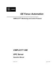
1 WelcomeCongratulations on your purchase of a <strong>Proficy</strong> TM <strong>Machine</strong> <strong>Edition</strong> product. Thispackage provides all the tools necessary to create powerful control and HMI (humanmachine interface) applications for a variety of run-time targets; a truly scalablesolution. <strong>Machine</strong> <strong>Edition</strong> supports the following products and features:■■■■■■■A fully-integrated environment. Every tool and editor works with the others.Logic Developer - PC, scalable, computer based control software with acomplete set of IEC standard editors (available with Quick Panel Controlproducts).Logic Developer - PLC, a software tool for programming the full line of GE FanucPLCs (See <strong>GFK</strong>-1918 <strong>Getting</strong> <strong>Started</strong> Logic Developer - PLC).View, for creating HMIs for Windows NT, Windows CE, and QuickPanel units.Motion Developer, for developing Whedco motion control applications.Web Access features that access real-time HMI data any time, from anywhere.Local Manager, a version control, security and audit trail system.LocalManagerViewLogicDeveloperPCLogicDeveloperPLCMotionDeveloper<strong>Machine</strong> <strong>Edition</strong> Environment(Development Tools)Build & DownloadRuntime FilesBuild & DownloadRuntime FilesBuild & DownloadRuntime FilesBuild & DownloadRuntime FilesControlStation NT/CEQuickPanelViewStation CEGE Fanuc PLCsMotion ControllersRemote I/OWeb AccessInternet/IntranetI/O ModulesMotors/Drives<strong>GFK</strong>-<strong>1868H</strong><strong>Machine</strong> <strong>Edition</strong> 5.50 1
1WelcomeSystem RequirementsSYSTEM REQUIREMENTSTo use <strong>Machine</strong> <strong>Edition</strong> and its tools, you require the following:Development Environment■Windows ® NT Professional version 4.0 with service pack 6a or later-or-Windows 2000 Professional (service pack 3 recommended)-or-Windows XP Professional (service pack 1 or later recommended)Note: Windows XP Tablet PC <strong>Edition</strong> is not supported.■■■■■Internet Explorer version 5.5 Service Pack 2 Q810847 or later, or InternetExplorer version 6.0 Service Pack 1 or later.Requirements for processor speed and memory are as follows:Minimum: 1 GHz Pentium-based processor with 256 MB RAMRecommended: 2 GHz Pentium-based processor with 512 RAMNote: For projects with more than 75,000 variables or variable elements, atleast 1 GB or RAM is strongly recommended.TCP/IP network protocol-based workstation.150-750 MB hard disk space, depending on the installed products.200 MB hard disk space for sample projects (optional).■Additional hard disk space for projects and temporary files.Note: Windows 98, NT, ME, 2000, and XP workstations require the Microsoft .NETFramework v1.1. If this is not yet installed, you will need approximately 150 MBadditional hard disk space when installing <strong>Machine</strong> <strong>Edition</strong>. The .NET Frameworkis automatically included with <strong>Machine</strong> <strong>Edition</strong>, so you do not need to install itseparately.Warning: After installation of <strong>Machine</strong> <strong>Edition</strong> and the .NET Framework iscomplete, do not attempt to install an older or beta version of the .NET Framework.This will cause the newest version of the .NET Framework to fail.2 <strong>Machine</strong> <strong>Edition</strong> 5.50<strong>GFK</strong>-<strong>1868H</strong>
WelcomeSystem RequirementsWindows ® NT Runtime■Thin install for Logic Developer - PC and View Developer. Runtime executablesare automatically updated from the development machine when the project isdownloaded.■Windows ® NT version 4.0 with service pack 4 or later-or-Windows 2000 Professional (service pack 3 recommended)-or-Windows XP Professional (service pack 1 recommended).■233 MHz Pentium-based workstation (500 MHz recommended)Note: 300 MHz is required on Windows 2000 or Windows XP Professional.■■64 MB RAM (128 MB recommended).200 MB free hard disk space.Windows ® CE Runtime■For HMI and Logic components: GE Fanuc ControlStation CE, ControlStation CEII, ControlStation CE IIx, or QuickPanel Control.■For HMI only: GE Fanuc ViewStation CE, ViewStation CE II, ViewStation CE IIx,or QuickPanel View.<strong>GFK</strong>-<strong>1868H</strong><strong>Machine</strong> <strong>Edition</strong> 5.50 3
1WelcomeInstallationINSTALLATIONFor last-minute information, release notes, and supported hardware lists for<strong>Machine</strong> <strong>Edition</strong> products, see the Important Product Information (IPI) documenton the CD. There are several ways to view this document■■■When installing <strong>Machine</strong> <strong>Edition</strong>, select Important Product Information on theinitial Launcher screen.From the <strong>Machine</strong> <strong>Edition</strong> Help menu, choose Important Product Information.When running <strong>Machine</strong> <strong>Edition</strong>, click the InfoView tab in the Navigator, thendouble-click the Important Product Information page under <strong>Getting</strong> <strong>Started</strong> inthe Table of Contents.■When running <strong>Machine</strong> <strong>Edition</strong>, click the Home button on the InfoViewertoolbar, then click the What’s New link under Get <strong>Started</strong> on the left hand side.If you have any problems installing <strong>Machine</strong> <strong>Edition</strong>, please contact TechnicalSupport (see page 8).To install the full <strong>Machine</strong> <strong>Edition</strong> development environment from a CD1. Insert the <strong>Machine</strong> <strong>Edition</strong> CD into your CD-ROM drive.Windows will automatically start the setup program. If the setup program does notautomatically start, run Setup.exe in the root directory of the CD.2. Click Install to start the install process.3. Follow the instructions as they appear on the screen.If a previous version of <strong>Machine</strong> <strong>Edition</strong> is installed on your workstation, you willbe prompted to uninstall <strong>Machine</strong> <strong>Edition</strong> during the upgrade process. You shoulddo so only when asked to by the installation process. Do not delete files left behindduring uninstallation; these will be used by the new version.To install only the View and Logic Developer - PC runtimes from a CD1. Insert the <strong>Machine</strong> <strong>Edition</strong> CD into your CD-ROM drive.If Windows automatically starts the setup program, cancel it by clicking Exit.2. In a Windows Explorer window, navigate to the Install\<strong>Proficy</strong> <strong>Machine</strong> <strong>Edition</strong> Runtime Install\Disk1 folder on the<strong>Machine</strong> <strong>Edition</strong> CD.3. Double-click the “Setup.exe” file in that folder.4. Follow the instructions as they appear on the screen.4 <strong>Machine</strong> <strong>Edition</strong> 5.50<strong>GFK</strong>-<strong>1868H</strong>
WelcomeProduct AuthorizationPRODUCT AUTHORIZATIONBefore you can start developing projects in <strong>Machine</strong> <strong>Edition</strong>, you must authorizethe software. If you do not do so, you will have unrestricted use of the software’sfeatures only for a short trial period. The authorization process takes only a fewmoments and allows you to take advantage of any product support for which youqualify.There are two types of authorization available: software key authorization andhardware key authorization. <strong>Machine</strong> <strong>Edition</strong> products can use a mixture ofauthorization types on a single workstation.To see what products you are currently authorized for, on the <strong>Machine</strong> <strong>Edition</strong>Help menu, point to Product Authorization and choose Authorize Software. Thisdisplays the Product Authorization dialog box. If you have a hardware key pluggedin to a USB port, you can select the Show Hardware Keys check box to view theauthorizations provided by that key.Hardware Key AuthorizationHardware key authorization requires a special USB hardware key. This keycontains internal settings that allow use of specific products, set by your dealer orretailer. Hardware keys can be used to authorize <strong>Machine</strong> <strong>Edition</strong> software only onthe development side: if you need to authorize a <strong>Machine</strong> <strong>Edition</strong> runtime, youmust use a software key (see page 6).Hardware key authorization is available only for Windows 2000 or Windows XPand requires a free USB port on your computer.To authorize <strong>Machine</strong> <strong>Edition</strong> products with a hardware key1. Locate a free USB port on your workstation.Typically, the USB port is located on the front or back of your tower case, or in theside of a laptop computer. In some cases, a USB port can be found on yourcomputer’s monitor.2. Plug the hardware key into the USB port.The first time you plug the key into a USB port, you will see a progress dialog boxthat indicates that Windows has detected new hardware and is updating its systemsettings. After the dialog box disappears, the settings stored in the hardware key areactive and you can use the <strong>Machine</strong> <strong>Edition</strong> products that it authorizes.<strong>GFK</strong>-<strong>1868H</strong><strong>Machine</strong> <strong>Edition</strong> 5.50 5
1WelcomeProduct AuthorizationYou must leave the hardware key in the port while using <strong>Machine</strong> <strong>Edition</strong>. If youremove the key from the port, authorization for those products vanishes, thoughyou can still use products previously authorized using a software key.To move authorization to another computer, simply remove the hardware key fromthe source computer and plug it into a USB port on the destination computer.Software Key AuthorizationWhen authorizing <strong>Machine</strong> <strong>Edition</strong> products with a software key, you will need tocontact us by telephone, fax, or e-mail. If you want to authorize your software bytelephone, note that authorization personnel are available only during regularbusiness hours (between 8 a.m. and 4 p.m. MST).Software key authorization is specific to a single computer or workstation. If youwant to work with <strong>Machine</strong> <strong>Edition</strong> on a different workstation, you must move theauthorization to that second workstation (see page 7).To authorize a copy of <strong>Machine</strong> <strong>Edition</strong> with a software key1. Have your serial number(s) ready. The serial numbers can be found on the License Key sheet that came with yourproduct.2. Run the Product Authorization program from the Start menu | Programs | GE Fanuc | <strong>Proficy</strong> <strong>Machine</strong> <strong>Edition</strong> |Product Authorization.The Product Authorization dialog box appears.3. Click Add.4. Select the medium with which you are authorizing: Internet, Phone/Fax/E-mail or Floppy Disk Transfer. Click Next.If you choose the Internet option, follow the instructions on the web site.If you choose the Phone/ Fax/ Email option, proceed to step 5.If you choose the Floppy Disk Transfer option, ensure you have an authorizationdisk to proceed.5. Fill in the fields in the dialog box. Fields that are identified with an asterisk (*) must be filled in.If authorizing online click Submit Authorization once the form is completed.If authorizing via phone/fax, click the Phone/Fax button once the form iscompleted and call the number on the screen to receive a new key code(s).If authorizing via e-mail, click the Send E-mail button once the form is complete.■■Phone. Phone the number listed on the screen to receive a new key code(s).Fax. Click Print FAX and fax the Product Authorization Request to us (our faxnumber will be on the print out). We will then reply by fax with your new keycode(s).6 <strong>Machine</strong> <strong>Edition</strong> 5.50<strong>GFK</strong>-<strong>1868H</strong>
WelcomeProduct Authorization■Internet. From the Authorization web page, click Submit Authorization. Wewill then reply by e-mail with your new key code(s).■E-mail. Click Authorize to e-mail us. We will then reply by e-mail with yournew key code(s).Product Authorization is complete after you enter the new key code and it hasbeen accepted. Depending on the product you have purchased, you may need torun the Product Authorization program a number of times. For example, if youbought ControlStation NT, you will need to authorize both Runtime andDevelopment.To move the authorization to another computerYou can run the software only on the computer that the Product Authorization wasrun on. If you want to develop your projects on a different computer, you will needto complete the following steps to move the authorization from one computer toanother.1. Install <strong>Machine</strong> <strong>Edition</strong> on the computer that the authorization will be moved to. Run the Product Authorizationprogram from the Start menu | Programs | GE Fanuc | <strong>Proficy</strong> <strong>Machine</strong> <strong>Edition</strong> | Product Authorization.The Product Authorization dialog box appears.2. Click Move and then click OK.There is a Target Site Code on the top right hand side of the screen. Write downthis site code carefully. It must be accurate for the move to work. You will need theTarget Site Code when you move the authorized software from the sourcecomputer.3. Click Authorize by disk.At this point, you need to go to the source computer that has the authorizedsoftware, and move the authorization to a disk.4. From the source computer, run the Product Authorization program.5. Click Move, and then click OK. Enter the Target Site Code that you wrote down from Step 3 and click Next. Verify thatthe site code is correct and click OK.6. Insert a blank formatted floppy disk into the floppy drive and click Next. The authorization code will be moved tothe disk and a dialog box should appear telling you it was successful. Click OK.7. Go back to the computer to which you are moving the authorization and insert the floppy disk. (The screen that isasking for an authorization disk should be displayed.) Click Next.8. Click Finish. A screen should appear telling you the move was successful. Click OK.The authorization has now been moved to the new computer.<strong>GFK</strong>-<strong>1868H</strong><strong>Machine</strong> <strong>Edition</strong> 5.50 7
1WelcomeTechnical SupportTECHNICAL SUPPORTSupport is available to registered users at no charge for 90 days after purchase. Asupport agreement can be purchased from your local GE Fanuc distributor ifextended support is required.If problems arise that can’t be solved using the information in your productmanual, online Help system, <strong>Proficy</strong> GlobalCare knowledge base, or the GE FanucTechnical Advisor knowledge base, contact us by telephone, fax, or mail. Whencontacting us, call from a telephone near your computer and have your <strong>Machine</strong><strong>Edition</strong> software running. Have the following information handy to help us assistyou as quickly as possible:■■■■The serial number from your installation CD case, and the Product name andversion number from the Help>About dialog box.The brand and model of any hardware in your system.Operating system and version number.The steps you performed prior to the problem occurring.North AmericaSupport Hotline: 1-800-GEFANUC (1-800-433-2682) Fax: (780) 420-2049Internet: http://www.globalcare.gefanuc.com Email: support@gefanuc.comComments about our manuals and help: doc@gefanuc.comMailing Address: GE Fanuc, 2700 Oxford Tower, 10235 - 101 St., Edmonton, AB, Canada, T5J 3G1South AmericaTelephone: +58 (261) 760 2862 Fax: +58 (261) 765 0909Internet: http://www.gefanuc.com (visit our Portuguese web site at www.gefanuc.com.br)E-Mail: luis.wilhelm@gefanuc.comMailing Address: GE Fanuc Automation Latin America, Calle 120 con Av. 17, Los Haticos -GE TurbimecaMaracaibo, VenezuelaEurope, the Middle East, and AsiaJapan: Telephone 81-3-5405-7555; fax 81-3-5405-7550China: Telephone 0086-21-32224555 x200; fax 0086-21-62793066Europe, the Middle East, and the rest Asia: + 800 1 GE FANUC or + 1 780-401-7717Internet: For up-to-date contact information, visit www.gefanuc-europe.com and click on “Offices and Services”.For up-to-date technical information visit www.gefanuc.com/support.E-mail: support.emea@gefanuc.com8 <strong>Machine</strong> <strong>Edition</strong> 5.50<strong>GFK</strong>-<strong>1868H</strong>
2 <strong>Proficy</strong> <strong>Machine</strong> <strong>Edition</strong><strong>Proficy</strong> <strong>Machine</strong> <strong>Edition</strong> offers you a complete solution for the development ofautomation applications under one roof. With <strong>Machine</strong> <strong>Edition</strong>’s integrateddevelopment environment and tools, you’ll spend more time building applicationsand less time learning the software.<strong>Machine</strong> <strong>Edition</strong> products are fully integrated with the environment and with eachother:■■■They share the same project database. No more wasted time synchronizing datapoints between applications!They share the same set of tools, providing a consistent user interfacethroughout the development process.They feature full drag-and-drop capabilities between tools and editors.■They feature a true scalable solution. You can choose what type of machineyour projects are downloaded to and will run on.The first part of this chapter provides an overview of the <strong>Machine</strong> <strong>Edition</strong>Environment. The second part provides some key <strong>Machine</strong> <strong>Edition</strong> concepts youneed to know before you begin. The third part shows how to open and exploresome of the sample projects included with a new <strong>Machine</strong> <strong>Edition</strong> installation.When you’ve finished, you’ll have a solid foundation for building your ownautomation projects.■For more help getting started, in the InfoView tab of the Navigator, expandthe <strong>Getting</strong> <strong>Started</strong> library.<strong>GFK</strong>-<strong>1868H</strong><strong>Machine</strong> <strong>Edition</strong> 5.50 9
2<strong>Proficy</strong> <strong>Machine</strong> <strong>Edition</strong>Quick StartQUICK START<strong>Machine</strong> <strong>Edition</strong> makes it easy to get started developing a project.To start <strong>Machine</strong> <strong>Edition</strong>1. On the Windows toolbar, click Start, point to Programs, then GE Fanuc, then <strong>Proficy</strong> <strong>Machine</strong> <strong>Edition</strong>,and then click <strong>Proficy</strong> <strong>Machine</strong> <strong>Edition</strong>. (See also page 26.)When <strong>Machine</strong> <strong>Edition</strong> initializes for the first time following installation, theEnvironment Themes dialog box appears.You can change the default theme later by clicking the Window menu and choosingApply Theme.2. Choose the environment theme you want to work in.3. Click OK.When you open a project, the appearance of your <strong>Machine</strong> <strong>Edition</strong> screen willmatch the preview in the Environment Themes dialog box. As you work, you willlikely modify the environment – opening and closing windows, changing theselected toolbars, and so on. Any changes you make are retained in your defaultenvironment setup.10 <strong>Machine</strong> <strong>Edition</strong> 5.50<strong>GFK</strong>-<strong>1868H</strong>
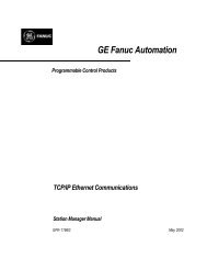
<strong>Proficy</strong> <strong>Machine</strong> <strong>Edition</strong>Quick StartThe <strong>Machine</strong> <strong>Edition</strong> dialog box appears.Select this option to create a new,empty project.Select this option to create a newproject based on a <strong>Machine</strong> <strong>Edition</strong>project template.Select this option to work on anexisting projectSelect this option to choose fromthose projects that have beenused recently.Select this option to choose from allexisting projectsSelect this option if you do not wantto see this dialog box again.4. Select the appropriate option to open a project. The Open an existing project option is selected by default.Notes:■If you select either Empty project or <strong>Machine</strong> <strong>Edition</strong> template, the New Projectdialog box appears to let you create a new project.■If you select Open an existing project, you can choose from Recent Projects (thedefault) or All Projects. You may need to also specify the location of the project:whether it is located on the local computer (My Computer), in a shared folder(Shared Projects), or on Manager Server (Server).5. If you selected the Open an existing project option, select the project that you want to open from the list.Existing projects include samples and tutorials that you can use to familiarizeyourself with <strong>Machine</strong> <strong>Edition</strong>.6. If desired, select the Don’t show this dialog box on startup option.7. Click OK.Your project opens in the <strong>Machine</strong> <strong>Edition</strong> environment that you specified in theEnvironment Themes dialog box. For more information, see “<strong>Machine</strong> <strong>Edition</strong>Projects” on page 25.<strong>GFK</strong>-<strong>1868H</strong><strong>Machine</strong> <strong>Edition</strong> 5.50 11
2<strong>Proficy</strong> <strong>Machine</strong> <strong>Edition</strong><strong>Machine</strong> <strong>Edition</strong> EnvironmentMACHINE EDITION ENVIRONMENTAll <strong>Machine</strong> <strong>Edition</strong> tools and editors appear in the <strong>Machine</strong> <strong>Edition</strong> window. Therun-time programs are separate Windows applications, so you can run a finishedapplication without starting <strong>Machine</strong> <strong>Edition</strong>.The following illustration shows a possible layout of the tools and a couple of theeditors available to you. Most of the time, you’ll be using only a few of these atonce—you can open and close tools and editors as you need them. Many tools arealso available only when editing a project. We’ll look at some of the tools in thefollowing section; for more details on the others, see the online Help.Navigator:Organizes and displaysproject information in atree structure.Toolchest:Containspreconfigured objectsthat can be draggedinto <strong>Machine</strong> <strong>Edition</strong>projects.Navigator tabs:Conveniently layersinformation about yourprojects.Inspector:Displays the propertiesof a selected object.InfoViewer:An embeddedbrowser used todisplay reports andcomprehensive help.Companion:A dynamic help windowthat providesinformation based onwhat you’re doing.FeedbackZone: Displaysoutput informationgenerated by<strong>Machine</strong> <strong>Edition</strong>components.Tabbed Editor window:One of many windows where you create and edit yourapplication. Tabs at the top let you switch between active TabbedEditor windows with the click of a mouse.Common <strong>Machine</strong> <strong>Edition</strong> ToolsData Watch:Displays the current statusof your project’s variables.12 <strong>Machine</strong> <strong>Edition</strong> 5.50<strong>GFK</strong>-<strong>1868H</strong>
<strong>Proficy</strong> <strong>Machine</strong> <strong>Edition</strong><strong>Getting</strong> to Know <strong>Machine</strong> <strong>Edition</strong>GETTING TO KNOW MACHINE EDITIONThe following are some key features of the <strong>Machine</strong> <strong>Edition</strong> environment. Knowingthem will make your first few hours with <strong>Machine</strong> <strong>Edition</strong> a breeze.Right-click, right-click, right-clickNo matter what object appears on your screen while using <strong>Machine</strong> <strong>Edition</strong>, youcan right-click it to perform operations on it. In fact, this is probably the mostcommon way you’ll get things done. <strong>Machine</strong> <strong>Edition</strong> tailors the menu ofcommands depending on the current status of your project.<strong>Getting</strong> HelpThere are many ways to access the <strong>Machine</strong> <strong>Edition</strong> online help system.■Press F1 on any selected item for context-sensitive help.■Browse through the table of contents in the InfoView tab of the Navigator.■■Perform a full-text search of the help in a separate HTML Viewer window: onthe Help menu, choose Search.Search for keywords using the index: on the Help menu, choose Index.■Use the Companion to dynamically display a brief description aboutwhatever item you have selected.You can also access additional help on the web. In <strong>Machine</strong> <strong>Edition</strong> on the Helpmenu, point to GE Fanuc on the Web, and then choose:■■Technical Advisor.GE Fanuc Home Page.<strong>GFK</strong>-<strong>1868H</strong><strong>Machine</strong> <strong>Edition</strong> 5.50 13
2<strong>Proficy</strong> <strong>Machine</strong> <strong>Edition</strong><strong>Getting</strong> to Know <strong>Machine</strong> <strong>Edition</strong><strong>Machine</strong> <strong>Edition</strong> provides two kinds of Help windows to display help information:the Companion and the InfoViewer.For detailed context-sensitive help, select any item (in thiscase, a button on a graphical panel) and press F1.To access the onlineHelp index, on theHelp menu, chooseIndex.To access the full-textsearch viewer, on theHelp menu, chooseSearch.Use the InfoViewertoolbar to navigate theHTML help.The InfoViewerwindow is a browserthat displays thecomprehensive HTMLbasedonline help.The InfoView Tabcontains the table ofcontents for the onlinehelp. Double-click apage to view it.Click this button to openthe InfoViewer withmore detailedinformation on the topicin the Companion.The Companion is adynamic help windowthat displays snippetsof information on anyselected item.<strong>Getting</strong> HelpCompanionInfoViewerThe Companion window displays brief information about whatever item youhappen to be working with, anywhere in <strong>Machine</strong> <strong>Edition</strong>. Whether you need themeaning of a property, the purpose of a node in the Navigator, or an explanation oferrors generated during validation, the Companion is always there for you.By default, the Companion is open while editing projects. If it’s been turned off,click on the Tools toolbar to open it again.The InfoViewer window is an embedded HTML browser that provides moredetailed and procedural help. It is launched whenever you access help topics fromthe InfoView Tab, the help index, or by pressing F1 on a selected item.Want to know more?In the Help Index, look up Help and choose “Finding information in theHelp”.14 <strong>Machine</strong> <strong>Edition</strong> 5.50<strong>GFK</strong>-<strong>1868H</strong>
<strong>Proficy</strong> <strong>Machine</strong> <strong>Edition</strong><strong>Getting</strong> to Know <strong>Machine</strong> <strong>Edition</strong>Accessing the Right ToolOften, <strong>Machine</strong> <strong>Edition</strong> Help will direct you to a specific tool window. If the toolisn't visible, there are two ways to open it:■■On the Tools menu, choose the tool name.On the Tools toolbar, click the tool icon. To display the Tools toolbar, on theTools menu, choose Toolbars and select a menu item.NavigatorControl I/OFeedback ZoneInspectorTools ToolbarInfoViewerCompanionToolchestData WatchIf you are not sure of the name of a tool within a toolbar, hover the mouse pointerover the tool’s button to display its name in a tool tip.Want to know more?In the Help Index, look up “Toolbars: an Overview”.Using docking markersIf the Show Docking Markers option is enabled, you can use docking markers tohelp dock a tool window to a desired location.As you drag a dockable window, a series of docking markers appear, indicatingvalid docking locations. Docking markers appear as a series of large blue arrows.Move the mouse over a docking marker to preview how the window would bedocked when using that marker. Release the mouse button while hovering over amarker to use that location.These markers dock tools to the edge of an existing tool or to the<strong>Machine</strong> <strong>Edition</strong> Environment window.This marker “stacks” the tool overtop an existing tool window,forming a series of tab-docked windows. You can then switchbetween tab-docked tools by clicking the tabs that appear at thebottom of the tab-docked windows.<strong>GFK</strong>-<strong>1868H</strong><strong>Machine</strong> <strong>Edition</strong> 5.50 15
2<strong>Proficy</strong> <strong>Machine</strong> <strong>Edition</strong><strong>Getting</strong> to Know <strong>Machine</strong> <strong>Edition</strong>Projects and the NavigatorNavigatorThe Navigator window organizes and manages your projects.■■Use the Navigator to create and manage projects, add targets and componentsto your project, set your environment preferences, create scripts, open editors,create variables, and more.The Navigator is organized into several tabs. The available tabs depend onwhich <strong>Machine</strong> <strong>Edition</strong> products are installed and whether a <strong>Machine</strong> <strong>Edition</strong>project is open. For example, the Project and Variables tabs appear only when a<strong>Machine</strong> <strong>Edition</strong> project is open.■Within each tab, items are displayed in a tree of nodes or folders. You canexpand and collapse the tree, just like folders in Windows Explorer.The following picture illustrates the Navigator prior to any projects being opened.All the files listed under My Computer are projects that you have access to on yourcomputer. The Samples folder contains sample projects and tutorials.Want to know more?In the Help Index, look up Navigator and choose “Navigator ToolWindow”.The Manager tab lists all projectslocated on your hard drive and (ifyou’re using a Manager system)under Manager. Use it to create andopen projects, and to manageprojects on a Manager system.To add a new project, right-clickMy Computer and choose New.orSelect Restore to add an existing orbacked-up <strong>Machine</strong> <strong>Edition</strong> project to yourcomputer.A <strong>Machine</strong> <strong>Edition</strong> project must be backedup before it can be moved to anothercomputer. To do this, right-click a projectlisted under My Computer and chooseBack Up.The Utilities tab contains useful toolsfor working on your projects. Availableutilities depend on which <strong>Machine</strong><strong>Edition</strong> products are installed.Navigator Window with Local Project ListThe InfoView tab contains thetable of contents for the Help.16 <strong>Machine</strong> <strong>Edition</strong> 5.50<strong>GFK</strong>-<strong>1868H</strong>
<strong>Proficy</strong> <strong>Machine</strong> <strong>Edition</strong><strong>Getting</strong> to Know <strong>Machine</strong> <strong>Edition</strong>To open a project in the Navigator1. In the Manager tab of the Navigator, right-click an existing project listed under My Computer and chooseOpen.The project is opened in <strong>Machine</strong> <strong>Edition</strong>. The Variables and Project tabs areadded to the Navigator and the nodes change to reflect those components thatmake up the project you just opened.Targets are the hardware devices andcomputers that your finished project will runon. A project can have multiple targets.These nodes represent thedifferent parts of your project.They appear when you addcomponents to a target.For example, the Control I/ODrivers, Ladder_Program, Logicand SFC folders appear when aLogic component was added toTarget1 (using Logic Developer -PC).The Options tab contains option andpreference settings for the <strong>Machine</strong><strong>Edition</strong> environment.The Project tab organizes your project. Use itto navigate around your project, and add,delete, and configure the items that make upyour project.The Variables tab contains all the variablesin your project. Use it to add, delete, move,and otherwise manipulate variables.Navigator Window with an Open Project<strong>GFK</strong>-<strong>1868H</strong><strong>Machine</strong> <strong>Edition</strong> 5.50 17
2<strong>Proficy</strong> <strong>Machine</strong> <strong>Edition</strong><strong>Getting</strong> to Know <strong>Machine</strong> <strong>Edition</strong>Properties and the InspectorInspectorIn <strong>Machine</strong> <strong>Edition</strong>, practically every object has properties. Properties are simplyattributes and information about that object. For example, the properties of a boxon an HMI graphical panel include Height, Width, Fill Color, and Outline Color.The properties of an object are edited in the Inspector window:■■■To edit an object’s properties, select it with the Inspector open. The Inspectorwill show all those properties associated with the selected object.When a property changes an object’s appearance, you’ll see the results of thechange immediately in the object’s editor.To see more properties for an object, select a tab at the bottom of the Inspector.This is the kind ofobject you selected.If you’re ever unsure of the valid range for a property,hover the mouse over its current value and look at thestatus bar at the bottom of the <strong>Machine</strong> <strong>Edition</strong> window.To edit this property, typethe new value in the box.To edit this property, select thenew value from the list box.To edit this property, clickthe button.Properties are organizedmuch like Windows folders.Click to expandthe list of subproperties.Click to collapsethe list of subproperties.Inspector WindowAs you select the various properties within the Inspector, the Companion willdisplay a brief description of the selected property.Want to know more?Select a tab for more properties.In the Help Index, look up Inspector and choose “Inspector ToolWindow”.18 <strong>Machine</strong> <strong>Edition</strong> 5.50<strong>GFK</strong>-<strong>1868H</strong>
<strong>Proficy</strong> <strong>Machine</strong> <strong>Edition</strong><strong>Getting</strong> to Know <strong>Machine</strong> <strong>Edition</strong>Data Watch ListsNavigator: Project tabData Watch nodesThe Data Watch (available only while editing a project) is a debugging tool thatyou can use to monitor and edit real-time values of variables defined in yourproject. This is useful while working online with a run-time target. With the DataWatch tool you can monitor individual variables or user-defined watch lists ofvariables. You can change variable values and force the state of discrete (BOOL)variables. Watch lists can be imported, exported, or saved with a project.There are three tabs in the Data Watch tool:■The Static tab shows variables added to the Data Watch tool.■■The Auto tab contains variables selected in the variable list or associated withthe currently-selected instruction in ladder logic.The Watch List tab contains all variables in the currently selected watch list. Awatch list lets you create and save a separate list of variables to monitor. Youcan define more than one watch list, but only one watch list can be monitoredin the Data Watch tool at a time.Want to know more?In the Help Index, choose “Data Watch List”.The IEC or Reference address ofvariables mapped to I/O terminals orPLC memory.The structure variableRobot1 has been expandedto show all of its elements.The name and value of each elementof the structure variable Robot1 isshown here, even when notexpanded.Double-click a value to change it.The Static tab containsvariables that you add to theData Watch tool.The Auto tab displays variablesassociated with the item currentlyselected in an editor or tool.A Watch List tab contains all variables in yourproject that have been added to the currentlyselectedWatch list.Data Watch WindowTo define a Watch List:1. Right-click the Data Watch Lists folder and choose New.2. Double-click the new Watch List to open it in the Data Watch tool.3. Add variables to the Data Watch as desired.The changes to the watch list are automatically saved for later use.<strong>GFK</strong>-<strong>1868H</strong><strong>Machine</strong> <strong>Edition</strong> 5.50 19
2<strong>Proficy</strong> <strong>Machine</strong> <strong>Edition</strong><strong>Getting</strong> to Know <strong>Machine</strong> <strong>Edition</strong>Smart ListsWhile working in <strong>Machine</strong> <strong>Edition</strong> editors, you are frequently required to inputvariable names, instruction mnemonics, and other data items. The Smart List canspeed text entry of these items.This text changes color based onwhether the entry is valid or invalid.For example, invalid entries are red.Valid entries in the list are black.Valid typed entries that are not in thelist appear green; accepting thisentry creates a new item (in thiscase, a new variable).Smart List DisplayThis tells you what you need to enter or select.As you type in the input box, the list selectionjumps to the item that is closest to what youtyped. Press ENTER to create a new item basedon what is typed, or use the Down arrow touse the selected item.For example, if you typed “fill” in the SmartList, the FillLevel variable would behighlighted. If you want to use an existingvariable (in this case, “FillLevel”), use theDown arrow to select the highlighted item,then press ENTER. To create a new variablecalled “fill”, simply press ENTER without usingthe Down arrow.20 <strong>Machine</strong> <strong>Edition</strong> 5.50<strong>GFK</strong>-<strong>1868H</strong>
<strong>Proficy</strong> <strong>Machine</strong> <strong>Edition</strong><strong>Getting</strong> to Know <strong>Machine</strong> <strong>Edition</strong>The ToolchestToolchestThe Toolchest (available only while editing a project) is a repository ofpreconfigured object templates you can drag into your project. These objects canbe as simple as a single ladder logic instruction, or as complex as a robotic armwith fully-configured ladder logic and HMI animation.While <strong>Machine</strong> <strong>Edition</strong> comes with a set of preconfigured object templates, youcan create your own—and since you can add as many copies of them as you want,this can save you hours of development time.Want to know more?In the Help Index, look up Toolchest: an Overview.Toolchest items are groupedinto drawers. Select the draweryou want with this list box.Within a drawer, Toolchest itemsare organized into folders.You can drag these logicinstructions directly intoyour ladder program.The Ladder, HMI, and SFCdrawers contain simpleinstructions and functions.Other drawers containfxClasses—definitions forfully-configured objectsthat you can also drag intoyour project.Toolchest WindowDefinitions of most preconfigured objects within the Toolchest are displayed in theCompanion.<strong>GFK</strong>-<strong>1868H</strong><strong>Machine</strong> <strong>Edition</strong> 5.50 21
2<strong>Proficy</strong> <strong>Machine</strong> <strong>Edition</strong><strong>Getting</strong> to Know <strong>Machine</strong> <strong>Edition</strong>The Feedback ZoneFeedback ZoneThe Feedback Zone (available only while editing a project) is an interactivewindow that displays output information generated by <strong>Machine</strong> <strong>Edition</strong>-enabledcomponents. Using the Feedback Zone, you can keep track of project information,locate validity errors within your project, display generated reports, and more. It isorganized into several tabs. Click on a message to display more information aboutthe error in the Companion Window.Want to know more?In the Help Index, look up “Feedback” and choose “Feedback ZoneTool Window”.Press F4 to cycle throughentries in the Feedback Zone.In the Build Tab (shown),Reports Tab, and ReferencesTab, pressing F4 also opens theproject you to the location ofthe selected item..The Build tab displays the status andresults of a validate or downloadoperation. Use this tab to discover and fixany errors you may have in your project.The References tab displays a list of all the places a selected variable is used in aproject. Click the Reference tab and then select a variable from the Variable List.You will see a list of all the places the variable is referenced in your project.The Import tab displays a list of errors and warningsfrom an import operation (for example,errors/warnings will be listed when you importvariables from a PLC into a <strong>Machine</strong> <strong>Edition</strong> project).The Reports tab displays a list of all reportsgenerated during the current session. Double-clicka report in the list to redisplay it in the InfoViewer.The Messages tab tracks and displays operations thathave been completed within <strong>Machine</strong> <strong>Edition</strong> (eg., amessage is added every time you open a project).Feedback Zone22 <strong>Machine</strong> <strong>Edition</strong> 5.50<strong>GFK</strong>-<strong>1868H</strong>
<strong>Proficy</strong> <strong>Machine</strong> <strong>Edition</strong><strong>Getting</strong> to Know <strong>Machine</strong> <strong>Edition</strong>Managing VariablesVariables are named storage spaces for data values defined in <strong>Machine</strong> <strong>Edition</strong>projects. A variable could store the current velocity of a motion controller motor,the height of a robotic arm, or any other value that an application needs to keeptrack of. Most variables in a project can be shared among various components andtargets, such as View panels and Logic Developer - PC’s ladder logic.You manage variables in the Variables tab of the Navigator, also called theVariable List. Like most items in <strong>Machine</strong> <strong>Edition</strong>, you configure variables byediting their properties in the Inspector.The values a variable can store depends on its data type. For example, a DINT datatype indicates that the variable can store “Double Integers”, 32-bit values. Thelocation where a variable’s value is stored is indicated by its data source. Typically,a variable’s value is either stored internally in the target’s memory or is retrieved(and sent) to external PLC hardware, via an I/O terminal or other connection.Available data types and data sources depend on the target type and (if applicable)components added to the target.You can also use arrays and structure data types in <strong>Machine</strong> <strong>Edition</strong> projects. Anarray is a series of variable elements with identical data types, referenced by a 0-based index (as in “MyArray[3]”). A structure data type is a group of variableelements that may or may not have the same data type, referenced by the name ofeach element (as in “MyStructure.MyElement”). Custom structure data types arecreated with fxClasses in the Toolchest.Want to know more?In the Help Index, look up “STRUCTURE data types”.Property ColumnsIn addition to the Inspector, with the three buttons at the top of the Navigator, youcan edit variable properties in a spreadsheet-like column view.Click to open and close the property column display. This button is available only in the Variables tab.Click to dock and undock the Navigator window. Undocking the Navigator (that is, making it work likean Editor window) can make it easier to work with properties in the column view.Click to display a list of available property columns. Double-click a property to add it to the current set.<strong>GFK</strong>-<strong>1868H</strong><strong>Machine</strong> <strong>Edition</strong> 5.50 23
2<strong>Proficy</strong> <strong>Machine</strong> <strong>Edition</strong><strong>Getting</strong> to Know <strong>Machine</strong> <strong>Edition</strong>When opened, the Navigator’s property columns view consists of a grid of cells:This grey box indicates the item whoseproperty you are editing.This black box indicates that the columnsupports “incremental dragging”. Click anddrag the box downwards to fill in the cellsunderneath with consecutive values, basedon the value of the starting cell.The Navigator’s Property Columns viewCells for properties that don’t apply to anitem are grayed out.Variable ReportsWhile you can generate reports on many things in <strong>Machine</strong> <strong>Edition</strong>, they areespecially useful for the Variable List. Among the available reports are:■■■■All variables by name, filtered or unfiltered.Cross-references to variables (that is, the places they are used in the project).All forced variables (Logic Developer - PC and Logic Developer - PLC only).Unused variables (that is, variables with no references anywhere in the project).The unused variables report also has a link that lets you delete all unusedvariables from the project at once.Reports are displayed as HTML pages in the InfoViewer. To generate a report, clickanywhere in the Variables tab then, on the File menu, select Report.Want to know more about Variables? Look up the following in the Help Index:■ For information on variables in general, choose “Variables: an Overview”.■ For information on variables in View, choose “Variable support in View Developer”.■ For information on variables in QuickPanel projects, choose “Variable support inQuickPanel applications”.■ For information on variables in Logic Developer - PC, choose “Variable support in LogicDeveloper - PC”.■ For information on variables in Logic Developer - PLC, choose “Variables in LogicDeveloper - PLC vs. Memory in GE Fanuc PLCs: an Overview”.■ For information on variables in Motion Developer, choose “Variable support in MotionDeveloper”.■ For information on importing variables from other applications or database files, chooseone of the “Importing Variables...” topics.24 <strong>Machine</strong> <strong>Edition</strong> 5.50<strong>GFK</strong>-<strong>1868H</strong>
<strong>Proficy</strong> <strong>Machine</strong> <strong>Edition</strong><strong>Machine</strong> <strong>Edition</strong> ProjectsMACHINE EDITION PROJECTSDuring development, your automation application is called a project. Each<strong>Machine</strong> <strong>Edition</strong> project is made up of targets and (sometimes) components. Atarget represents the hardware platform where the finished project runs, such as aWindows NT computer, a Windows CE unit, a motion controller, or a QuickPanelunit. Different <strong>Machine</strong> <strong>Edition</strong> products support different target types. Targets areoften further subdivided into models, such as the ViewStation and ControlStationversions of Windows CE targets. Components add specific capabilities to a target.Available components depend on the target type, model, and what <strong>Machine</strong><strong>Edition</strong> products you have installed.For example, with View, you can you add an HMI component to Windows NT andWindows CE targets, used for creating human-machine interfaces. With LogicDeveloper - PC, you can add a Logic component to Windows NT and WindowsCE targets. You can then create ladder logic to make a PC act as a Controller. ViewonlyWindows CE targets do not support logic; therefore you cannot download aproject that contains logic to one.With Motion Developer, you can program motion controllers from your PC. Eachmotion device programmed by Motion Developer is represented by a separateMotion target. Since motion targets have no additional capabilities, addingadditional components is not necessary.Want to know more?Sharing Projects between <strong>Machine</strong> <strong>Edition</strong> WorkstationsIf your site has multiple <strong>Machine</strong> <strong>Edition</strong> workstations connected through anetwork, you can use the Shared Projects folder to work on the same set ofprojects. Projects under the Shared Projects folder are stored in a directory youspecify, typically a shared directory on the network.No access or version control is applied to the Shared Projects folder. If multipleusers open the same project at the same time, some changes may be lost.Note: Shared Projects and Shared Variables are two completely different andseparate features. For information on Shared Variables (which implement proxyvariables between targets in different projects), see “PLC Access I/O” on page 79.Want to know more?In the Help Index, look up projects and choose “<strong>Machine</strong> <strong>Edition</strong>Projects: an Overview”.In the Help Index, look up “Shared Projects”.<strong>GFK</strong>-<strong>1868H</strong><strong>Machine</strong> <strong>Edition</strong> 5.50 25
2<strong>Proficy</strong> <strong>Machine</strong> <strong>Edition</strong><strong>Machine</strong> <strong>Edition</strong> ProjectsRunning a Sample Project (View/Logic Developer - PC)If you’re using View or Logic Developer - PC, we’ve provided some sampleprojects that show basic operations of <strong>Machine</strong> <strong>Edition</strong>. Take a few minutes tocomplete the following steps and learn the basics of project development in<strong>Machine</strong> <strong>Edition</strong>.■For a more detailed example of creating projects, in the Help Index, look upTutorial and choose one of the topics listed there.To run a sample project1. Run <strong>Machine</strong> <strong>Edition</strong> from the Start menu | Programs | GE Fanuc | <strong>Proficy</strong> <strong>Machine</strong> <strong>Edition</strong>.2. In the Manager tab of the Navigator, double-click one of the sample applications listed under theMy Computer folder.Sample applications include■■■■■■■Alarm Trends: an HMI application that demonstrates alarms and charts.Animation Features: an HMI application that depicts the various types ofanimation available in View.Brewery: an HMI and logic brewery application that runs on a Windows NTtarget.Car Wash: an HMI and logic application that runs on a Windows NT target.This application is built in an SFC document.ControlStation HMI Features: an HMI and logic application that runs on aWindows NT target. This application also shows some web documents.FC2000 Brewery: an HMI and logic brewery application that runs on aControlStation/ViewStation CE. (Projects containing a logic component cannotbe downloaded to a ViewStation, as ViewStation CEs do not support logic.)FC2000 Zone Control: an HMI and logic application that runs on aControlStation/ViewStation CE. This application runs a four-zone ventilationlogic system. It is to be used with the ControlStation/ViewStation CE Tutorial.(Since ViewStation CE targets do not support logic, projects with a logiccomponent cannot be downloaded to a ViewStation.)■ST - Lunar Lander: an HMI and logic application that runs on a Windows NTtarget. This project demonstrates the Structured Text (ST) language and itsinteraction with UDFBs (User Defined Function Blocks).Tutorials include■Animation: an HMI application that illustrates and provides details on thevarious animations that you can use in your HMI.26 <strong>Machine</strong> <strong>Edition</strong> 5.50<strong>GFK</strong>-<strong>1868H</strong>
<strong>Proficy</strong> <strong>Machine</strong> <strong>Edition</strong><strong>Machine</strong> <strong>Edition</strong> Projects■■■■AppExec: an HMI application that demonstrates the AppExec Script function.Keystrokes: an HMI application that displays the analog values associated withthe keys on your keyboard.Logging: an HMI application that demonstrates how to log production data toan ASCII text file.Recipes: an HMI application that shows how one would load and modifyrecipes.■Scripting: an HMI application that demonstrates some of View Developer’sscripting capabilities.3. Browse through the project in <strong>Machine</strong> <strong>Edition</strong>.Open the project’s graphical panels, ladder logic, and SFCs (if they exist) in theirrespective editors. To open an editor, right-click the appropriate node in theProject tab of the Navigator and choose Open.Also, take a look at the properties of the various nodes and objects. To view anobject’s properties, open the Inspector window, and then select an object.4. In the newly opened project, press F9 to validate, download, and run the sample application.The F9 key is a shortcut for the Run command which automatically starts ViewRuntime and the Controller.The sample application should now be running in both View Runtime and theController. View Runtime appears, displaying the first panel of the project’s HMI.You can see the real-time status of the logic by going online to the Controller. Forinformation about going online to the Controller, see “To go online to theController” on page 27.To go online to the ControllerIf you have chosen a project that contains logic and/or an SFC document, you cango online to the application and watch the logic being executed.1. Minimize the Runtime window (but don’t close it) and return to <strong>Machine</strong> <strong>Edition</strong>.2. In the Project tab of the Navigator, right-click the Target node and choose Go Online.You are now online to the Controller (that is, you are working with the applicationwhile it is running). The Controller is the part of the Runtime that solves logic andSFCs.3. In the Project tab of the Navigator, open the Ladder Editor by double-clicking the Ladder Program node oropen the SFC Editor by double-clicking the SFC node.In the editor, you can watch the logic being solved as the Controller operates. Youcan start and stop Runtime and the Controller by right-clicking the target,pointing to Online Commands, and selecting Start/Stop Runtimes from the<strong>GFK</strong>-<strong>1868H</strong><strong>Machine</strong> <strong>Edition</strong> 5.50 27
2<strong>Proficy</strong> <strong>Machine</strong> <strong>Edition</strong><strong>Machine</strong> <strong>Edition</strong> Projectssubmenu. To go offline from the Controller, right-click the target and choose GoOffline.Developing a <strong>Machine</strong> <strong>Edition</strong> ProjectThe first thing you have to decide when you create a <strong>Machine</strong> <strong>Edition</strong> project iswhere the project will run after it is developed. That is, on what type of targethardware it will run.For View and Logic Developer - PC, targets can be a Windows NT computer(either the one you’re developing the project on, or a remote one that you connectto through a network), a Windows CE unit (a ControlStation/ViewStation CE, CE II,CE IIx, or QuickPanel View/Control).For View alone, your target can also be a conventional QuickPanel unit.For Logic Developer - PLC and Logic Developer - State, your target is a GE FanucPACSystems controller, Series 90 PLC, or VersaMax PLC. You can also configureremote I/O targets that represent a variety of remote I/O adapters and theirassociated I/O modules (See <strong>GFK</strong>-1918 <strong>Getting</strong> <strong>Started</strong> Logic Developer - PLC).If you’re using Motion Developer, the choice is easy—simply determine whetheryour motion hardware is a motion controller/drive or a drive-only device (see page95).After you’ve decided on the target, you need to determine which components yourproject will include: HMI (with View) and/or Logic (with Logic Developer - PC).Note that ViewStations do not support Logic components. A project can havemultiple targets of different types with various components running on each target.In some cases, targets can be converted from one type to another. For example,you can convert a Windows NT target to and from a QuickPanel View target.Want to know more?In the Help Index, look up “Targets: an Overview”.To create and develop a projectThe following procedure introduces the general steps involved in creating a projectusing a template, and downloading a project to a target computer.1. Start <strong>Machine</strong> <strong>Edition</strong> from the Start menu | Programs | GE Fanuc | <strong>Proficy</strong> <strong>Machine</strong> <strong>Edition</strong>.2. Create a project using a template.In the Manager tab of the Navigator, right-click My Computer and chooseNew. The New Project dialog box appears.If you’re using shared projects, you can also add new projects under the SharedProjects folder. Or, if you are working on a Manager system, you can add newprojects to the <strong>Machine</strong> <strong>Edition</strong> folder under the Server.28 <strong>Machine</strong> <strong>Edition</strong> 5.50<strong>GFK</strong>-<strong>1868H</strong>
<strong>Proficy</strong> <strong>Machine</strong> <strong>Edition</strong><strong>Machine</strong> <strong>Edition</strong> Projects3. In the New Project dialog box, type a name for the new project, select a template, and click OK.A description of the template appears below your selection. You can clickhypertext links in the description for details on the template components.At this point, you need to know the type of target hardware to which your projectwill download, as this will determine which template you choose. In some projecttemplates (such as the “View/Control” template), you can select this as one ofseveral parameters within an HTML page on the template dialog box.The project is opened in <strong>Machine</strong> <strong>Edition</strong> and the Navigator changes to reflectthose components that make up the project you just created.4. In the Variable List, create variables for your application.In the Variables tab of the Navigator, right-click the Variable List node, point toNew Variable, and choose the type of variable you want to create.By default, the Variable List node filters out all system variables. Systemvariables are created automatically when you add components to Windows NT,CE, QuickPanel, or PLC targets. To display all variables including system variables,right-click the Variable List node, point to Filter By, and choose No Filter.5. Create your application.With Logic Developer - PC, add logic (Ladder, Il, ST, SFC) to your project andconfigure a control I/O driver to model your hardware. If the template you chosedid not include a Logic component, add one now—right-click the target, point toAdd Component, and choose Logic. (View-only targets don’t support logic.)■In the Project tab of the Navigator, under the Logic folder, open the LadderEditor by double-clicking the Ladder Program node.■Drag ladder instructions from the Toolchest into the editor. You can findladder instructions in the Ladder drawer of the Toolchest.■■Want to know more?Want to know more?Assign variables to instructions. You can do this with the Smart List, whichappears when you insert or double-click an instruction. Or, drag a variable fromthe Variables tab of the Navigator and drop it on the instruction you want itmapped to.You can add additional logic blocks (IL, ST) and organize your logic with SFC.Want to know more?In the Help Index, look up templates and choose “Creating a New<strong>Machine</strong> <strong>Edition</strong> Project” or “Creating a new project under a ChangeManagement system”.In the Help Index, look up “Variables: an Overview”.In the Help Index, look up “Ladder Instructions: an Overview (PC)”.<strong>GFK</strong>-<strong>1868H</strong><strong>Machine</strong> <strong>Edition</strong> 5.50 29
2<strong>Proficy</strong> <strong>Machine</strong> <strong>Edition</strong><strong>Machine</strong> <strong>Edition</strong> ProjectsWith View, create the graphical panels and animation for your project. If thetemplate you chose did not include an HMI component, then add one now—rightclickthe target, point to Add Component, and choose HMI. (If a target has both anHMI and a Logic component, you’ll typically create the Logic component first.)■In the Project tab of the Navigator, open the Panel Editor by double-clickinga panel node.■Use the Graphical Panel toolbar to create your HMI and/or drag graphicalobjects from the Toolchest onto a panel. You can find a set of fully-configuredobjects (complete with animation) in various Toolchest Expert Objects drawers.With Motion Developer, begin by running the Motion Expert wizard.■If necessary, open the “Main Wizard” home page by right-clicking the targetand choosing Main Wizard.■In the wizard page, click Motion Expert and follow the instructions on screen.For more information on using wizards, see page 100.6. If necessary, configure the I/O hardware connections for your project.■For Logic Developer - PC, set up Control I/O in the Control I/O Driversfolder (in the Project tab of the Navigator). To add a driver, right-click theControl I/O Drivers folder and choose New Driver. Use the Control I/O tool toconfigure your drivers. Map variables to I/O terminals.■For View, set up PLC Access I/O in the PLC Access Drivers folder. To add adriver, right-click the PLC Access Drivers folder and choose New Driver.Configure the drivers in the Inspector window. On NT targets, you might wantto set up OPC I/O in the OPC Client folder.7. When your project is complete; validate, download, and run your project by pressing the F9 function key.<strong>Machine</strong> <strong>Edition</strong> saves the project, performs a validation, builds the run-time files,and attempts to establish a connection to the target computer.Validating and Downloading a ProjectDuring project development, you will go through the validation and downloadprocesses several times. The validation process checks the project for errors. If theproject contains errors, they are listed in the Build tab of the Feedback Zone.■Want to know more?In the Help Index, look up “Control I/O Tool: an Overview”.All errors must be fixed before the download process can proceed. Warningsare also listed in the Feedback Zone, but they do not prevent the downloadfrom starting.30 <strong>Machine</strong> <strong>Edition</strong> 5.50<strong>GFK</strong>-<strong>1868H</strong>
<strong>Proficy</strong> <strong>Machine</strong> <strong>Edition</strong><strong>Machine</strong> <strong>Edition</strong> ProjectsPreparing a Remote NT target for DownloadingWhen fixing project errors, use the F4 function key to scroll through errors in theFeedback Zone, jumping to their locations in the project.The download process involves two steps. The first step creates (or “builds”) all therun-time files necessary for a target to perform its role in a completed project. Thesecond downloads those files to the target devices or computers.■■For Motion Developer, the easiest way to set up the motion control device fordownloading is with the Set Communication Parameters wizard. Open theMain Wizard page for the target (right-click the target and select Main Wizard).Then, point to Target Configuration and select Communication Parameters.Click Finish when you’re done.To download a View or Logic Developer - PC project to the Windows NTcomputer on which you are developing (a local target), ensure that the targetproperty Computer Address is set to “.” (without the quotation marks).Otherwise—for remote targets—type the IP address or computer name of theremote computer you want to download to, in the Computer Address property.■To download a QuickPanel project, ensure that the target property ComputerDownload Port is set to the applicable COM port.Additional basic information on setting up Windows NT and CE targets follows.The following steps need to be completed on a remote Windows NT targetcomputer before you can download a project to it.1. If you are downloading to another NT computer (other than the ControlStation or Windows CE unit), ensure that therun-time files are installed on that device.ViewStation and ControlStation targets are shipped with the run-time filespreinstalled. If you’re using your own Windows NT computer, you’ll have to installthe run-time files yourself from the <strong>Machine</strong> <strong>Edition</strong> installation CD (see page 4).2. Share the <strong>Machine</strong> <strong>Edition</strong> installation directory with the development computer that contains the project files.In the Windows NT Explorer, navigate to the <strong>Proficy</strong> <strong>Machine</strong> <strong>Edition</strong> folder, rightclickit and choose Sharing. Click Shared As and in the Share Name field, type<strong>Proficy</strong> <strong>Machine</strong> <strong>Edition</strong>.3. Ensure you have the proper permissions to download files to the target computer.Start the Windows NT User Manager (from the Taskbar, click Start, point toPrograms, Administrative Tools, and choose User Manager). Double-click theGuest user in the top half of the display. Clear the Account Disabled check box. InWindows 2000, open the Control Panel, click Administrative Tools, and then clickComputer Management. Expand “System Tools” and then expand “Local Usersand Groups”.<strong>GFK</strong>-<strong>1868H</strong><strong>Machine</strong> <strong>Edition</strong> 5.50 31
2<strong>Proficy</strong> <strong>Machine</strong> <strong>Edition</strong><strong>Machine</strong> <strong>Edition</strong> Projects4. Within your <strong>Machine</strong> <strong>Edition</strong> project, specify the IP address or computer name of the remote NT target in theComputer Address target property. This enables <strong>Machine</strong> <strong>Edition</strong> to locate and connect to the NT target computer.Type the IP address or the computername of the remote NT target to whichyou want to download your project files.Want to know more?In the Help Index, look up “Preparing Windows NT targets fordownloading”.Preparing a Windows CE target for downloadingThe following steps need to be completed on the Windows CE, CE II, CE IIx, andQuickPanel View/Control targets before you can download a project to it. If youare not physically connected to the CE unit but want to test your project, you candownload the project to your local computer by setting the Use Simulator targetproperty to True. Note that you cannot download a project that contains a logiccomponent to a View-only target, because they do not support logic.1. Physically connect the View-only target, Windows CE unit to the Ethernet network. This step may require the help ofa network administrator.2. Within your <strong>Machine</strong> <strong>Edition</strong> project, specify the IP address of the Windows CE unit in the Computer Address targetproperty.To find the IP address of a Windows CE unit, double-tap the System Informationicon located on the desktop of the CE unit.By default, the CE unit uses a DHCP (Dynamic Host Configuration Protocol) IPaddress. This means that the IP address is dynamically assigned by the Ethernet32 <strong>Machine</strong> <strong>Edition</strong> 5.50<strong>GFK</strong>-<strong>1868H</strong>
<strong>Proficy</strong> <strong>Machine</strong> <strong>Edition</strong><strong>Machine</strong> <strong>Edition</strong> Projectsnetwork server using DHCP. If you want to use a fixed IP address, you mustmanually set the IP address on the Windows CE unit.Want to know more?In the Help Index, look up “Preparing CE and QuickPanel View/Controltargets for downloading”.Type the IP address of the CE unit towhich you want to download your projectfiles.Testing a View ProjectThe following steps introduce you to the Quick Test feature. Quick Test is similar toa preview in that it allows you to quickly see the results of any changes you’vemade to a graphical panel without having to download your entire project.NOTEThe Quick Test feature is not available on QuickPanel targets.Before you can use Quick Test, your project must have been downloaded at leastonce to the target computer. If you want to Quick Test a graphical panel from aWindows CE unit (or a QuickPanel View/Control) project, you must set the target’sUse Simulator property to True and perform at least one download after changingthe setting.To Quick Test changes made to a graphical panel1. Ensure that you’ve downloaded the HMI to the target computer at least once.2. If you haven’t already done so, open the graphical panel you want to test.3. Right-click in the panel and choose Quick Test.View Runtime appears with a preview of the graphical panel.<strong>GFK</strong>-<strong>1868H</strong><strong>Machine</strong> <strong>Edition</strong> 5.50 33
Logic Developer - PC3 Logic Developer - PCLogic Developer - PC is <strong>Machine</strong> <strong>Edition</strong>’s PC Control product, where you edit aproject’s logic component. With Logic Developer - PC you create control programsusing standard IEC 61131-3 editors in a graphical environment. The programs youcreate are downloaded to and executed on the PC Logic Controller. You interfaceto a plant or process through the I/O system of your choice; Logic Developer - PCsupports a wide range of industry standard hardware.Logic Developer - PC supports Windows NT, Windows CE, and QuickPanelControl/View targets. All user-defined logic programs are contained in theLogic folder, including the following:■Sequential Function Chart (SFC) editor (see page 37)■Ladder Program (see page 41)■Instruction List Blocks (see page 45)■Structured Text Blocks (see page 48)■Function Block Diagram (see page 51)Navigator: Project tabThe following run-time elements are included with Logic Developer - PC:■Logic Developer - PC Web Access (see page 55)■Control I/O Drivers (see page 58)■PC Logic Controller (on target computer) (see page 61)TIP User-defined folders can be added to the Logic folder or to another user-definedfolder to organize your logic. A user-defined folder can contain any type of logic blockcontained in the logic folder, except ladder (of which there can be only one).<strong>GFK</strong>-<strong>1868H</strong><strong>Machine</strong> <strong>Edition</strong> 5.50 35
3Logic Developer - PCTo create a project that includes a logic componentTo add a logic component to an existing project1. In the Manager tab of the Navigator, right-click My Computer and choose New.The New Project dialog box appears.2. In the Project Name box, enter a name for your project.3. From the Project Template list, choose a template that includes a logic component.A preview of what each template includes is displayed as you select differenttemplates.4. Click OK.Your new project is created and the Project tab is opened in the Navigator.• In the Project tab of the Navigator, right-click a target, point to Add Component and choose Logic.The Logic folder with an empty ladder program and SFC component is added toyour project.To add a user-defined folder to your project1. Ensure that your project contains a logic component (see above).2. Right-click the Logic folder or a user-defined folder, point to New, and then choose Folder.The new folder appears in the Project tab of the Navigator in alphabetical order.3. (Optional) Enter a name for the new folder.36 <strong>Machine</strong> <strong>Edition</strong> 5.50<strong>GFK</strong>-<strong>1868H</strong>
Logic Developer - PCSFC EditorSFC EDITORSFC logic is a graphical language for organizing the sequential execution ofcontrol logic. The SFC editor is an easy-to-use graphical tool for editing sequentialfunction charts in the <strong>Machine</strong> <strong>Edition</strong> environment. With the SFC editor, you canwork on a disk copy of a sequential function chart (offline) or monitor theexecution of an SFC running in the Controller (online). You can also configure theappearance and behavior of the SFC editor.Sequential Function ChartNavigator: Project tabSFC nodesTo add a new SFCAn SFC is much like a flow chart; it is a high level control program that organizesdetailed blocks of logic into a state-like flow. In general, an SFC consists of stepsalternating with transitions. A transition can be a BOOL variable or a StructuredText statement, which resolves to a BOOL value. Each step represents a state thatthe program is in until the transition following it allows execution to proceed to thenext step. Each step contains actions that are user-defined sections of ladder, IL, ST,or FBD logic. The actions in a step are executed in the order they are listed and arerepeated each Controller scan while the step is active. Each action in a step has aqualifier associated with it that determines when and how the action will beexecuted.An SFC document is a grid of cells. Each cell can contain an instruction. Theinstruction set includes steps, transitions, branches, parallels, and jumps.An SFC can be expanded by adding macros. Each macro is a special SFCdocument that can be referenced any number of times from its SFC document orother macros.Want to know more?In the Help Index, look up macro and choose “SFC Macro”. You canalso look up “SFC Tutorial” in the online help Index. This tutorial takesyou step-by-step through the creation of a Sequential Function Chartthat controls traffic signals.1. In the Project tab of the Navigator, right-click the Logic folder or a user-defined folder, point to New, andthen choose SFC.The new SFC appears under the Logic folder or a user-defined folder inalphabetical order.2. (Optional) Enter a unique name for the new SFC.<strong>GFK</strong>-<strong>1868H</strong><strong>Machine</strong> <strong>Edition</strong> 5.50 37
3Logic Developer - PCSFC EditorTo open an SFC or macro for editing• In the Project tab of the Navigator, under the Logic folder or under a user-defined folder, double-click anSFC or macro node.The SFC editor opens with the document ready for editing.To create a new SFC macro1. In the Project tab of the Navigator, under the Logic folder or under a user-defined folder, right-click anSFC or macro node and choose New.2. (Optional) Enter a unique name for the new macro.Your new macro appears as a child node of the SFC or macro node you startedwith.Working with the SFC editor - OfflineThe SFC editor interacts with the <strong>Machine</strong> <strong>Edition</strong> tools to provide maximumflexibility when editing a program. The following picture illustrates some of theoperations you can perform.Configure instructionsand their associatedvariables in theInspector.Call a macro with aMacro Step instruction.Insert instructions,rows, and columnswith the SFC toolbar.Drag instructions fromthe SFC drawer of theToolchest to the SFCeditor.Use the Variable Listto create variablesthen drag them toinstructions in theSFC editor.Right-click a blank cellto start editing.The Companionprovides help onanything you click.Locate all instances ofa variable (References)or syntax errors(Build).38 <strong>Machine</strong> <strong>Edition</strong> 5.50<strong>GFK</strong>-<strong>1868H</strong>
Logic Developer - PCSFC EditorTo insert an SFC instruction1. In the SFC editor, right-click a blank cell and choose Place Instruction.2. Choose an instruction mnemonic from the smart list that appears and press ENTER to finish.You can set the SFC editor options to automatically assign default variables toinstructions or to allow you to choose and create your own.To Quick Edit an SFCSFC Operators• In the SFC editor, click a blank cell and type instruction mnemonics separated by operators (see the following table).Press ENTER to finish.Each mnemonic specifies one or more instructions. Each operator moves thelocation of the currently selected cell. Default variables are assigned when QuickEditing an SFC.To ... Use ...move right one cell +move left one cell -move down one cell ;stay on current cell /<strong>GFK</strong>-<strong>1868H</strong><strong>Machine</strong> <strong>Edition</strong> 5.50 39
3Logic Developer - PCSFC EditorWorking with the SFC editor - OnlineThe SFC editor allows you to view the execution of an SFC as it happens. Thefollowing picture illustrates this capability.Active steps andtransitions arehighlighted inbold.Power flow in theassociated ladderprogram (actions) isindicated in bold whileactions are executed.Right-click anyBOOL to turn orforce it On or Off.Many actions can beviewed at once.The References tab of theFeedback Zone lists allinstances of a variable.Click an entry to locate itin an editor.Use the Data Watch tomonitor or changedata values in realtime.To go online to the Controller’s SFC• In the Project tab of the Navigator, right-click the target and choose Go Online. (Before you can go online tothe Controller, you must first download the project.)The Controller’s SFC appears in the SFC editor. When the Controller is running,active steps and transitions are graphically indicated.40 <strong>Machine</strong> <strong>Edition</strong> 5.50<strong>GFK</strong>-<strong>1868H</strong>
Logic Developer - PCLadder EditorLADDER EDITORLadder logic may be the most popular language in use today for creating controlprograms. The ladder editor is a graphical tool for editing ladder programs in<strong>Machine</strong> <strong>Edition</strong>. With the ladder editor, you can work on a disk copy of a ladderprogram (offline) or with a live program as it runs in the Controller (online). Youcan also configure the appearance and behavior of the editor under the Optionstab of the Navigator.Ladder ProgramNavigator: Project tabladder logic nodesA ladder program is composed of rungs of ladder logic instructions that executesequentially from left to right, top to bottom. The instruction set includes standardIEC 61131-3 functions supplemented by a large library of advanced and I/Ospecific functions. Along with rungs and instructions, a ladder program contains:■Labels: Each default (START and END) or user-defined label is a rungproviding an entry point for program execution.■Subroutines: Each user-defined subroutine is a separate, reusablesection of logic that can be called from anywhere in a ladder program.■Actions: Each action is a separate block of logic that can be referencedin a Sequential Function Chart.TIPYou can also create User-Defined Function Blocks (UDFBs). Each UDFB is a callablesubroutine to and from which that you can pass parameters.Want to know more?In the Help Index, look up ladder and choose “Ladder Program: anOverview”. You can also look up “UDFB” and choose “User-definedFunction Blocks: an Overview”.To open a ladder program for editing• In the Project tab of the Navigator, under the Logic folder, double-click the Ladder_Program node.Your ladder program opens in the ladder editor.To locate a label• In the Project tab of the Navigator, under the Logic folder, under the Ladder Program folder, doubleclicka label node.Your ladder program, subroutine or action opens in a ladder editor window withthe label selected.<strong>GFK</strong>-<strong>1868H</strong><strong>Machine</strong> <strong>Edition</strong> 5.50 41
3Logic Developer - PCLadder EditorTo create a new subroutine or action1. In the Project tab of the Navigator, under the Logic folder, under the Ladder Program folder, right-clickthe Subroutines or Actions node and choose New.2. (Optional) Enter a unique name for the new subroutine or action.An empty subroutine or action, labeled with the name you entered, iscreated. Double-click the node to open it for editing. You can add ladder logic tothe subroutine or action as required.Working with the ladder editor - OfflineThe ladder editor interacts with all of the <strong>Machine</strong> <strong>Edition</strong> tools to providemaximum flexibility when editing a program. The following picture illustratessome of the operations you can perform.Click a shunt and typemnemonics to insertinstructionsInsert rungs andcommon instructionswith the ladderInstruction toolbar.Drag variables toinstruction parametersto configure them.Drag branches aroundinstructions to createparallel executionpaths.Display subroutinesand actions inseparate editorwindows.The Companion tracksyour moves, providinginformation on whatyou click.To insert a rungEdit descriptions inplace for rungs,variables, and yourladder program.Drag instructions fromthe PC LadderInstructions drawer ofthe Toolchest.Locate all instances ofa variable (References)or syntax errors(Build).• In the ladder logic, right-click a rung, shunt, label or description and choose Insert Rung.An empty rung is inserted. You can set the editing options for the ladder editor sothat rungs are inserted either before or after the current selection.42 <strong>Machine</strong> <strong>Edition</strong> 5.50<strong>GFK</strong>-<strong>1868H</strong>
Logic Developer - PCLadder EditorTo Quick Edit ladder logic• In the ladder logic, click a rung and type instruction mnemonics separated by semicolons, and then press ENTER.The instructions specified by the mnemonic string you entered will be inserted, inorder, on the rung. You can enter mnemonics followed by variable names if youwant to assign instruction parameters while Quick Editing.Example: Add a Normally Open Contact (NO) instruction followed by a Coil(OUT) instruction and assign the variables MySwitch and MyCoil to theseinstructions respectively.NO MySwitch; OUT MyCoilWorking with the ladder editor - OnlineWith the ladder editor you can go online to a ladder program being run by theController (page 61). While online, you can view the power flow through theladder logic and watch data values change in real time. You can also edit theladder program, just as you would while offline, with the following restrictions:■Labels, subroutines, and actions cannot be deleted while online.■Only one rung can be changed before writing the changes to the Controller.The following picture illustrates the ladder editor while online to the Controller.Online status is indicatedby the color of thetarget icon.Lightning bolts in eachcorner indicate theController’s status andchange to reflect faultconditions.New or edited rungs areindicated withalternately colored andbolded lines until youWrite Changes.Power flow is indicatedwith bold colored lines.Data values aredisplayed in real timeas they change eachscan by the Controller.Use the Data Watch toview or set data valuesfor any variable in yourproject.<strong>GFK</strong>-<strong>1868H</strong><strong>Machine</strong> <strong>Edition</strong> 5.50 43
3Logic Developer - PCLadder EditorTo go online to the Controller’s ladder program• In the Project tab of the Navigator, right-click the target and choose Go Online. (Before you can go onlineto the Controller, you must first download the project.)The Controller’s ladder program appears in the ladder editor. When the Controlleris running, power or state flow is graphically indicated and data values updated.To write a changed rung to the Controller• From the Controller menu, choose Write Changes. (The Controller menu is available only when the ladder editor isselected.)The Controller’s ladder program is updated with the single altered rung.44 <strong>Machine</strong> <strong>Edition</strong> 5.50<strong>GFK</strong>-<strong>1868H</strong>
Logic Developer - PCInstruction List EditorINSTRUCTION LIST EDITORIL logic is one of four languages specified by the IEC 61131-3 standard. The ILeditor is an easy-to-use, intelligent, free-form text editor for editing IL blocks in the<strong>Machine</strong> <strong>Edition</strong> environment. With the IL editor, you can work on a disk copy ofan instruction list (offline) or monitor the execution of an IL block running in theController (online). You can also configure the appearance and behavior of theeditor under the Options tab of the Navigator.Instruction ListNavigator: Project tabIL block nodesIL is a low-level language composed of basic and advanced Math instructions thatexecute sequentially from top to bottom. IL blocks can also contain labelsproviding entry points for program execution. In its simplest form an IL can:1. Load a data value (operand) into the accumulator.2. Perform an operation on the accumulator, saving the result in the accumulator.3. Store the accumulator’s value to memory (a variable).4. Do another accumulator load or operation, etc.Want to know more?In the Help Index, look up “IL” and choose “IL Editor”.To open an IL block for editingIn the Project tab of the Navigator, under the Logic folder or under a userdefinedfolder, double-click an IL block node.Your IL block opens in the IL editor.To create a new IL block1. In the Project tab of the Navigator, right-click the Logic folder or a user-defined folder point to New,and select Instruction Language.2. (Optional) Enter a name for the new IL block and then press ENTER.Your new IL block appears as a child node of the Logic folder or a user-definedfolder.NOTEIL blocks can be executed only when called as Actions from an SFC.<strong>GFK</strong>-<strong>1868H</strong><strong>Machine</strong> <strong>Edition</strong> 5.50 45
3Logic Developer - PCInstruction List EditorWorking with the IL editor - OfflineThe IL editor interacts with the <strong>Machine</strong> <strong>Edition</strong> tools to provide maximumflexibility when editing a program. The following picture illustrates some of theoperations you can perform.Drag variables tothe IL editor tocomplete ILstatements.Copy and paste anIL statement(s)from the IL editor toother sections or ILblocks.Multiple-line blockcomments todocument your ILblock.In-line comments forindividual ILstatements.Begin typing for aSmart List to appear(see page 20).The Companiontracks your moves,providinginformation onwhat you click.Locate all instancesof a variable withthe References tabof the FeedbackZone.To insert an IL instruction1. In the IL editor, just begin typing. A smart list will appear containing any items (labels, mnemonics or variables) thatare applicable at the current cursor position.2. Enter or choose from the list the mnemonic you want.To convert a name to a variable1. In the IL editor, right-click a name and point to Create “name” as.2. Choose a data type from the list that appears.46 <strong>Machine</strong> <strong>Edition</strong> 5.50<strong>GFK</strong>-<strong>1868H</strong>
Logic Developer - PCInstruction List EditorWorking with the IL editor - OnlineThe IL editor allows you to view the execution of an IL block as it runs. This isillustrated in the following diagram.Online status isindicated by the colorof the target icon.Variable types andtheir data values aredisplayed in realtime as they changeeach scan by theController.The grey backgroundindicates that theeditor is online to theController and isread-only.Right-click any BOOLvariable to force itOn/Off or to turn itOn/Off.Use the Data Watchtool to view or setdata values for anyvariable(s) in yourproject.To go online to the Controller’s IL1. In the Project tab of the Navigator, for each of the following right-click the target and choose:2. Validate (F7).3. Download (F8).4. Run (F9).5. Go Online (CTRL+F11).The Controller’s IL block appears in the IL editor as read-only and with a greybackground. In the IL editor, you can monitor the values of a variable, by clickingon the variable. You can also change or force BOOL variable states.<strong>GFK</strong>-<strong>1868H</strong><strong>Machine</strong> <strong>Edition</strong> 5.50 47
3Logic Developer - PCStructured Text EditorSTRUCTURED TEXT EDITORST logic is one of four languages specified by the IEC 61131-3 standard. The STeditor is an easy-to-use, intelligent, free-form text editor for editing ST blocks in the<strong>Machine</strong> <strong>Edition</strong> environment. With the ST editor, you can work on a disk copy ofa structured text block (offline) or monitor the execution of an ST block running inthe Controller (online). You cannot edit an ST online.Structured TextNavigator: Project tabST block nodesST is a high-level language composed of basic and advanced Math instructions. STblocks can be executed as Actions called from SFC Steps, or when called as asubroutine from other ST blocks or ladder programs.If there is an ST block named ‘MAIN’, it will execute after the SFC programs. Thatis, after downloading a Logic Developer - PC application, the execution of everyscan will begin with the ladder program, then any SFC programs, and then the STblock named MAIN.ST supports a timer, arrays, bitwise access, strings, and User Defined FunctionBlocks (UDFBs—callable subroutines to and from which you can pass parameters).The Return keyword causes an early exit from a subroutine.Want to know more?In the Help Index, look up “ST Editor (PC)” or look up “UDFB” andchoose “User Defined Function Blocks: an Overview”.To open an ST block for editingIn the Project tab of the Navigator, under the Logic folder or under a userdefinedfolder, double-click an ST block node.Your ST block opens in the ST editor.To create a new ST block1. In the Project tab of the Navigator, right-click the Logic folder or a user-defined folder, point to New, andthen choose ST Block.2. (Optional) Enter a name for the new ST block.Your new ST block appears under the Logic folder or under a user-defined folder.48 <strong>Machine</strong> <strong>Edition</strong> 5.50<strong>GFK</strong>-<strong>1868H</strong>
Logic Developer - PCStructured Text EditorWorking with the ST editor - OfflineThe ST editor interacts with the <strong>Machine</strong> <strong>Edition</strong> tools to provide maximumflexibility when editing a program. The following picture illustrates some of theoperations you can perform.Drag variables to theST editor to completeST statements.Multiple-line blockcomments todocument your STblock.Hover over avariable with themouse pointer tosee its data type.Copy and paste STstatements from theST editor to othersections or ST blocks.In-line comments forindividual STstatements.The Companiontracks your movesprovidinginformation on whatyou click.Locate all instancesof a variable in theReferences tab ofthe Feedback Zone.To insert an ST instruction1. In the ST editor, just begin typing. To see a list of valid variables, right-click anywhere and choose Insert Variable.Choose a variable from the list that appears, then press ENTER.2. To obtain a list of valid mnemonics, right-click anywhere and choose Insert Keyword. Choose a keyword from thelist that appears, then press ENTER.<strong>GFK</strong>-<strong>1868H</strong><strong>Machine</strong> <strong>Edition</strong> 5.50 49
3Logic Developer - PCStructured Text EditorWorking with the ST editor - OnlineThe ST editor allows you to view the execution of an ST block as it runs. This isillustrated in the following diagram.Online status isindicated by the colorof the target icon.The grey backgroundindicates that theeditor is online to theController and isread-only.Variable types andtheir data values aredisplayed in realtime as they changeeach scan by theController.Right-click any BOOLvariable to force itOn/Off or to turn itOn/Off.Use the Data Watchtool to view or setdata values for anyvariable(s) in yourproject.To go online to the Controller’s ST1. In the Project tab of the Navigator, for each of the following right-click the target and choose:2. Validate (F7).3. Download (F8).4. Run (F9).5. Go Online (CTRL+F11).The Controller’s ST block appears in the ST editor as read-only and with a greybackground. In the ST editor, you can monitor the values of a variable, by clickingon the variable. You can also change and/or force BOOL variable states.50 <strong>Machine</strong> <strong>Edition</strong> 5.50<strong>GFK</strong>-<strong>1868H</strong>
Logic Developer - PCFunction Block Diagram EditorFUNCTION BLOCK DIAGRAM EDITORFunction Block Diagram (FBD) logic is one of four languages specified by the IEC61131-3 standard. The FBD editor is a graphical, free-form editor for editing FBDlogic in the <strong>Machine</strong> <strong>Edition</strong> environment. With the FBD editor you can work on adisk copy of a function block diagram (offline) or monitor the execution of an FBDrunning in the Controller (online). You cannot edit an FBD online.Function Block DiagramNavigator: Project tabFBD nodesTo open an FBD for editingTo create a new FBDA Logic Developer - PC FBD is a named section of Function Block Diagram logicthat is compiled and downloaded to the PC represented by the parent target. Thegraphical FBD language can be used where there is a flow of signals betweencontrol blocks.FBDs can be executed as Actions called from SFC Steps or called from other FBDs,ladder programs, and ST blocks. An FBD can contain instructions, wires, andvariables, as well as ladder user-defined function blocks (UDFBs), and ST UDFBs.Want to know more?In the Help Index, look up “FBD: an Overview (PC)”.In the Project tab of the Navigator, under the Logic folder, or under a userdefinedfolder, double-click an FBD node.Your FBD opens in the FBD editor.1. In the Project tab of the Navigator, right-click the Logic folder or a user-defined folder, point to New,and then choose Function Block Diagram. A new, empty FBD with the default name “FBDBlkn” appears inthe Navigator in alphabetical order under its folder.2. (Optional) Enter a unique name for the FBD.Your new FBD appears under the Logic folder or under a user-defined folder.<strong>GFK</strong>-<strong>1868H</strong><strong>Machine</strong> <strong>Edition</strong> 5.50 51
3Logic Developer - PCFunction Block Diagram EditorWorking with the FBD editor - OfflineThe FBD editor interacts with the <strong>Machine</strong> <strong>Edition</strong> tools to provide maximumflexibility when editing a program. The following picture illustrates some of theoperations you can perform.Drag variables to theFBD editor tocomplete FBDinstructions.Drag instructionsfrom the PC FBDInstructions drawerof the Toolchest.The Companion tracksyour moves providinginformation on whatyou click.Locate all instancesof a variable in theReferences tab of theFeedback Zone.To insert an FBD text box (Toolchest method)1. If you have not already done so, open the Toolchest.2. In the Toolchest, choose the PC FBD Instructions drawer.3. Expand the Comment Block folder.4. Drag the text box from the Toolchest onto a blank area of the FBD editor. You can now enter text in the FBD editor.To insert an FBD text box (FBD editor method)1. In the FBD editor, right-click a blank area and choose Insert Instruction. A smart list appears.2. In the smart list, do one of the following:Enter the word “text” (without quotes), and then press ENTER.52 <strong>Machine</strong> <strong>Edition</strong> 5.50<strong>GFK</strong>-<strong>1868H</strong>
Logic Developer - PCFunction Block Diagram Editor-or-Scroll down the list, choose Text, and then press ENTER.3. You can now enter text in the FBD text box.To insert an FBD instruction (Toolchest method)1. If you have not already done so, open the Toolchest.2. In the Toolchest, choose the PC FBD Instructions drawer3. Expand an FBD instruction group.To insert an FBD instruction (FBD editor method)4. Drag an FBD instruction from the Toolchest onto a blank area of the FBD editor.5. Assign parameters above (for Call, Counter, and Timer instructions) and beside the FBDinstruction, or draw wires to or from the FBD instruction.1. In the FBD editor, right-click a blank area and choose Insert Instruction. A smart list appears.2. In the smart list, enter or choose an FBD instruction.3. Assign parameters above (for Call, Counter, and Timer instructions) and beside the FBD instruction, or draw wires toor from the FBD instruction.<strong>GFK</strong>-<strong>1868H</strong><strong>Machine</strong> <strong>Edition</strong> 5.50 53
3Logic Developer - PCFunction Block Diagram EditorWorking with the FBD editor - OnlineThe FBD editor allows you to view the execution of an FBD as it runs. This isillustrated in the following diagram.Online status isindicated by thecolor of the targetThe greybackgroundindicates that theeditor is online to theController and isread-only.Right-click any BOOLvariable to force itOn/Off or to turn itOn/Off.Use the Data Watch tool to view or setdata values for any variable(s) in yourproject.Online FBD editing is not possible. However, you can change or force BOOLvariable states. While online, you can also watch data variables in the Data Watchtool.To watch a variable’s value• In the FBD editor, right-click a variable whose value you want to monitor and choose Watch. The variable is addedto the Data Watch tool for monitoring.54 <strong>Machine</strong> <strong>Edition</strong> 5.50<strong>GFK</strong>-<strong>1868H</strong>
Logic Developer - PCLogic Developer - PC Web AccessLOGIC DEVELOPER - PC WEB ACCESS<strong>Machine</strong> <strong>Edition</strong> enables you to view a target’s PC logic data with a web browser,such as Microsoft Internet Explorer (v4.0 or later required). When a <strong>Machine</strong><strong>Edition</strong> project is downloaded, it automatically launches an integrated web server.Users who connect to the target computer over the web are presented with the SiteIndex, from which they can select the Logic Navigator. (If the target has an HMI,Web Access options for the HMI appear as well.)The Logic Navigator presents a tree diagram of PC logic stored in the Controller,where you can browse to specific programs and blocks:■Published SFCs and SFC macros.■■■■Ladder program.Ladder subroutines.Actions.ST blocks.To allow remote access to your project■IL blocksClick any logic block in the tree to view it.Want to know more?In the InfoView tab of the Navigator, expand the Web Access library,and then select a topic under the “PC Web Access features” book.1. For each target that you want to allow access to, set the target’s Publish Logic property to True.This enables all PC logic except SFCs and SFC macros to be remotely viewable.2. For each SFC and SFC macro in those targets that you want users to access, set its Publish property to True.For example, to allow users to view an SFC remotely, set the SFC’s Publish propertyto True.NOTEThe target containing the PC logic to be published must be set as the active target and asuccessful project download must occur.To access the PC logic Site Index1. Start Internet Explorer. You can also install Internet Explorer from the <strong>Machine</strong> <strong>Edition</strong> installation CD.2. In the Address box in Internet Explorer, enter the computer name or IP address of the run-time computer.3. If you’re not sure what the run-time computer’s name or IP address is, check the properties of the TCP/IP driver inthe Control Panel Network setup, or contact your network administrator.4. If you’re testing the project on the local computer, enter “localhost” (without the quotation marks) as the Address.This connects Internet Explorer with the local computer.<strong>GFK</strong>-<strong>1868H</strong><strong>Machine</strong> <strong>Edition</strong> 5.50 55
3Logic Developer - PCLogic Developer - PC Web AccessWhen you connect to the Run-time computer, the Site Index appears with a list oflinks to possible ways to view your process data.To view PC logic remotely1. Start Internet Explorer.2. In the Address box in Internet Explorer, enter the computer name or IP address of the run-time computer.The Site Index appears.3. Click Logic, and then click Logic Navigator.An index (tree diagram) appears, which contains all published PC logic.4. Click the SFC, SFC macro, ladder program, ST block, or IL block you want to view.The selected PC logic block appears. See To allow remote access to your projectabove for information on publishing PC logic.While viewing ladder logic remotely, values of variables can be viewed byhovering the mouse pointer over the variable. If a BOOL variable on a Coil orContact instruction is■Green, the variable is set to True (1).■Black, the variable is set to False (0).Values of variables in SFC Transitions (including Structured Text Transitionstatements) can be viewed by hovering the mouse pointer over the Transition. SFCTransitions that are:56 <strong>Machine</strong> <strong>Edition</strong> 5.50<strong>GFK</strong>-<strong>1868H</strong>
Logic Developer - PCLogic Developer - PC Web Access■Green have a result of True (1).■Black have a result of False (0).Click to go back to theLogic Developer - PCmain menu.Click an SFC action toview it remotely.Click to go to the GEFanuc home web page.Hover over an SFC transitionwith the mouse pointer toview its value or values.<strong>GFK</strong>-<strong>1868H</strong><strong>Machine</strong> <strong>Edition</strong> 5.50 57
3Logic Developer - PCControl I/O DriversCONTROL I/O DRIVERSA control program (SFC, ladder, IL, or ST) generally interfaces with the process it iscontrolling through some type of physical I/O equipment. For PC-based controlsystems this usually involves installing an adapter card in the target computer thatconnects to an industry standard I/O network. In this way, data generated by aprocess can be acquired and acted upon by the Controller as it executes itsprogram(s). Control I/O drivers provide the software required to connect theController with an adapter card and the I/O network of your choice.Want to know more?In the Help Index, look up “Control I/O Drivers”.I/O DriversNavigator: Project tabControl I/O nodesLogic Developer - PC comes complete with a growing library of drivers. Driversthat require no additional equipment on the target computer are the following:■ASCII: Allows you to use an existing communications port on the targetcomputer to send and receive ASCII formatted data to and from otherequipment.■Control Peer: Allows Controllers running on two or more computers to shareprocess data. Messages are passed via ethernet when variable values change.Other drivers require third-party adapters on the target computer. Logic Developer- PC supports most of today’s most popular I/O networks including the following:■Allen-Bradley RIO■ASCII 2■Control Peer■DeviceNet I/O 1, 2■Legacy DeviceNet I/O 1 ■Ethernet I/O 1, 2■GE Fanuc CNC I/O■GE Genius I/O 2■GE Fanuc Series 90-30 I/O 1,2 ■Honeywell SDS I/O■Interbus-S I/O■Modbus Slave 1, 2■Modicon MB + DistributedI/O■Modicon Quantum-800 Series I/O■PROFIBUS I/O 1,2 ■Legacy PROFIBUS I/O 1■VersaMax Expansion I/O 2 ■1. Also supported on Windows CE targets2. Also supported on QuickPanel Control targets58 <strong>Machine</strong> <strong>Edition</strong> 5.50<strong>GFK</strong>-<strong>1868H</strong>
Logic Developer - PCControl I/O DriversTo add a Control I/O driver to a target• Right-click the Control I/O Drivers node, point to New Driver then choose a driver from the list.The new driver appears as a child node under the Control I/O node. Adefault configuration of the driver is also added to the Control I/O tool. You canadd up to nine drivers to a target.Control I/O ToolControl I/OThe Control I/O tool is a special editor used to graphically model the I/Oequipment driven by Control I/O drivers. Each I/O system is displayed in a treestructure starting with a driver node branching down to terminals thatrepresent physical field connections. Between the driver and terminals are nodesrepresenting any cards, racks, or modules included in the system. Fielddata is shared with the components of your project by mapping variables to eachI/O terminal.Want to know more?In the Help Index, look up “Control I/O Tool”.<strong>GFK</strong>-<strong>1868H</strong><strong>Machine</strong> <strong>Edition</strong> 5.50 59
3Logic Developer - PCControl I/O DriversWorking with Control I/OThe Control I/O tool interacts with other <strong>Machine</strong> <strong>Edition</strong> tools to speed thecreation of your I/O system. The following picture illustrates some of theoperations you can perform.Drag variables fromthe ladder editor toControl I/O terminals.Use the Variable Listto create variablesthen drag them to I/Oterminals.IEC addresses can bedisplayed in a ladderprogram abovevariables mapped toI/O terminals.Double-click a node toconfigure a driver,card, rack, or slot.Double-click aterminal and type aname to create andmap a variable of thedefault type.View and edit datavalues for variablesmapped to I/Oterminals.To configure an I/O system with the Control I/O tool1. Right-click a driver, card, rack, or slot and choose Add xxx to build an I/O tree.2. Double-click a driver, card, rack, or slot node to configure it.3. Map variables to I/O terminals.60 <strong>Machine</strong> <strong>Edition</strong> 5.50<strong>GFK</strong>-<strong>1868H</strong>
Logic Developer - PCControllerCONTROLLERThe Controller is a run-time engine, hosted on afollowing operations in a repeated scan cycle:■■■■■target, that performs theSolves logic in a ladder program, including any called subroutines.Solves logic in an SFC, including any called actions.Solves ST block named ‘MAIN’ (if it exists), including any called subroutines.Solves FBD block named ‘MAIN’ (if it exists), including any called subroutines.Interfaces with Control I/O drivers.■Updates the target’s run-time database, which is shared with the View Runtime(see page 88).The following diagram illustrates the Controller’s scan cycle.Read from I/ONavigator: Project tabTarget nodeSolve ladderSolve SFCYieldSolve ST Block MainWrite to I/OSolve FBD Block MainLogic Developer - PC Run-time Controller Scan CycleThe Controller can be hosted on a:■Windows NT target. The Controller appears as a Logic Developer - PC systemservice.■Windows CE target. The Windows CE Controller appears as a Logic Developer -PC program running under Windows CE.■QuickPanel Control/View target. The Windows QuickPanel Control appears asa Logic Developer - PC Controller program running under Windows CE.<strong>GFK</strong>-<strong>1868H</strong><strong>Machine</strong> <strong>Edition</strong> 5.50 61
3Logic Developer - PCControllerYou specify a target when creating a project. The Controller automatically startswhen the target operating system is started.Want to know more?In the Help Index, look up “PC Logic Controller: an Overview”.To configure the ControllerWorking with the ControllerThe Controller’s location (IP address or computer name), performance (scan rate ortuning), and behavior (response to faults, watchdog timer, and shutdownprocedure) are configured by setting the properties of the target it resides on.1. In the Project tab of the Navigator, right-click a target and choose Properties.2. In the Inspector, adjust the properties.If your project includes an HMI component, properties of the View Runtime canalso be set at this time. You can also configure the Controller’s properties byselecting Properties from the Controller menu. In this case, the ControllerProperties dialog box opens. The information in the dialog box is the same as inthe Inspector—just represented differently.The logic component of a project must be downloaded to the Controller before theproject can be run.To download a logic component to the Controller• In the Project tab of the Navigator, right-click a target and choose Download.All components on the selected target are validated and then downloaded to thespecified computer, if no errors exist. Errors listed in the Build tab of the FeedbackZone must be corrected before a download can be completed. Logic componentsare downloaded to the Controller, while HMI components are downloaded to theView Runtime.Although the Controller service is always running, you still have control over theexecution of your control programs. Offline, you can start, stop, and resetexecution. When online to the Controller, additional commands are available topause, single-scan, or enable forces.62 <strong>Machine</strong> <strong>Edition</strong> 5.50<strong>GFK</strong>-<strong>1868H</strong>
Logic Developer - PCControllerRun Mode StoreTo run the ControllerRun Mode Store (RMS) functionality lets you update a target Controller’s programwithout stopping the Controller. It is supported on all Logic Developer - PC targets.When you attempt to download your project to the Controller, the Download toController dialog box appears with the following options.■■■Attempt a Run Mode Store: <strong>Machine</strong> <strong>Edition</strong> will attempt a Run Mode Storeoperation. That is, it will try to download your logic to the Controller while theController is running.Stop the Controller, then download: <strong>Machine</strong> <strong>Edition</strong> will not attempt to use theRun Mode Store feature. Instead, it stops the Controller before initiating thedownload operation.Download Retentive Initial Values: Choose whether to download initial valuesof retentive variables, which may have changed since the previous download.Several system tests and checks are performed when attempting a Run Mode Storeoperation. If these tests fail, the logic program may not be downloaded to theController.Want to know more?In the Help Index, look up “Run Mode Store (RMS) (PC)”.• In the Project tab of the Navigator, right-click a target, point to Online or Offline Commands, and chooseStart Runtime.The ladder program, SFC program(s) the ST block named ‘MAIN’, and the FBDblock named ‘MAIN’ begin executing on the target computer or unit. If the targetalso has an HMI component (see page 88), the View Runtime is started at the sametime as the Controller.To validate, download and run a project, right-click a target and chooseDownload and Start “targetname”.Warm StandbyThe Warm Standby feature provides an extra level of reliability for criticalWindows NT and Windows CE applications. It consists of two Controllers runningthe Logic Developer - PC Controller (a primary and secondary or warm standbyController), and an I/O switch that determines which Controller is currentlyconnected to the physical I/O.When a system using warm standby is started, the primary Controller is connectedto the I/O, solves logic, and updates the secondary Controller with critical data.The secondary Controller receives the data and monitors the status of the primary<strong>GFK</strong>-<strong>1868H</strong><strong>Machine</strong> <strong>Edition</strong> 5.50 63
3Logic Developer - PCControllerController. When a fault is detected in the primary Controller, or when thesecondary Controller can’t communicate with the primary Controller, the I/Oconnection is automatically switched to the secondary Controller and thesecondary Controller takes over operations.Working with Warm StandbyYou must set up the warm standby hardware before you can configure the warmstandby system.Want to know more?In the Help Index, look up “warm” and choose “Warm Standby”.To configure Warm Standby1. In the Project tab of the Navigator, right-click a Windows NT or Windows CE target and choose Properties.2. In the Inspector, scroll to the +Redundant System group of properties and double-click it to expand thegroup.3. Click the Redundant Mode property and choose Warm Standby.4. Click the Controller Mode property and choose a value from the list.64 <strong>Machine</strong> <strong>Edition</strong> 5.50<strong>GFK</strong>-<strong>1868H</strong>
Logic Developer - PCControllerHot StandbyThe Hot Standby feature provides a high level of reliability for critical Windows NTapplications. It consists of two Controllers running the Logic Developer - PCController (a primary and secondary or hot standby Controller) over a GE GeniusI/O network. The GE Genius driver automatically handles the switching betweenthe Controllers.To download to a target with hot standby, the primary and secondary Controllersmust be synchronized, that is, they must both be downloaded.By default, the primary Controller is active and the secondary Controller is thebackup. The backup Controller sets itself to active when:■A fault occurs.■A loss of communication occurs with the active Controller via the VMIPCI-5565 reflective memory cards.■The target's Secondary Switch Time has elapsed.Both Controllers can read from the network, however, only the active Controllercan write to the network.Working with Hot StandbyYou must set up the hot standby hardware before you can configure the hotstandby system.Want to know more?In the Help Index, look up “hot” and choose “Hot Standby”.To configure Hot Standby1. In the Project tab of the Navigator, right-click a Windows NT target and choose Properties.2. In the Inspector, scroll to the +Redundant System group of properties and double-click it to expand thegroup.3. Click the Redundant Mode property and choose Hot Standby.4. Click the Secondary Address property and enter the IP address (Controller name) of the secondary Controller.5. Click the Secondary Switch Fault property and choose the type of fault the secondary Controller will become activeon.6. Click the Secondary Node ID property and assign a unique node ID to the VMIPCI-5565 card of the secondaryController.7. Click the Secondary Switch Time (ms) property and enter the number of milliseconds the secondary Controller is towait for communication from the primary Controller.8. Click the Primary Node ID property and assign a unique node ID to the VMIPCI-5565 card of the primary Controller.<strong>GFK</strong>-<strong>1868H</strong><strong>Machine</strong> <strong>Edition</strong> 5.50 65
3Logic Developer - PCController9. Click the Primary Wait Time (ms) property and enter the number of milliseconds the primary Controller is to wait forcommunication from the secondary Controller.OPC Servers, Warm Standby, and Hot StandbyWarm standby and hot standby are fully supported by the Logic Developer - PCOPC server for <strong>Machine</strong> <strong>Edition</strong>. When a configuration file is detected, the OPCserver:■Generates internal objects so that it will recognize all warm standby or hotstandby configurations as logical Controllers to OPC clients.■Creates predefined OPC items for each logical Controller. These items indicatewhich physical Controller is active and the statuses of the primary andsecondary Controllers.To configure an OPC server for Hot Standby and Warm Standby• Edit the “OPCWarmStandby.HTML” file, located in the same folder as LogicPC_OPC.EXE on the computer hosting theOPC Server.This XML file is used for both the Warm Standby and Hot Standby features. Bydefault, this file is located in the “C:\Program Files\GEFanuc\<strong>Proficy</strong> <strong>Machine</strong> <strong>Edition</strong>\OPC” directory.66 <strong>Machine</strong> <strong>Edition</strong> 5.50<strong>GFK</strong>-<strong>1868H</strong>
4 ViewView is the human-machine interface (HMI) component of <strong>Machine</strong> <strong>Edition</strong>,providing the means to organize, track, display, and affect data from your plant orprocess. With View you create graphical panels, write scripts, configure alarm andlogging schemes, and eventually launch the project in View Runtime. On NT/CEtargets, Web Access features let you publish data from <strong>Machine</strong> <strong>Edition</strong> HMIs forremote viewing over the Internet.View supports HMI creation for Windows NT, Windows CE, QuickPanel, andQuickPanel View/Control targets. Most View tools and editors are common to alltargets, but a few are QuickPanel-specific; for details, see “QuickPanelApplications” on page 90.The following are included with a View HMI component:■Panel EditorNavigator: Project tabHMI component nodes■Script Editor■Alarms■PLC Access Drivers■Language translation support■Message groups■Logging (NT/CE targets only)■OPC Client & Servers (NT/CE targets only)■Web Documents (NT/CE targets only)■View Runtime (NT/CE targets only)To create a project that includes an HMI component■Password security (QuickPanel targets only)1. In the Manager tab of the Navigator, right-click My Computer and choose New.The New Project dialog box appears.2. In the Project Name box, type a name for your project.3. From the Project Template list, choose “Configuration Wizard (View / Control)”.4. In the preview pane, select the desired parameters for your new application (such as the target type and model).5. Click OK.Your new project is created and the Project tab is opened in the Navigator.<strong>GFK</strong>-<strong>1868H</strong><strong>Machine</strong> <strong>Edition</strong> 5.50 67
4ViewPanel EditorNavigator: Project tabPanel NodesPANEL EDITORThe Panel Editor is used to develop the layout of each panel in your HMIapplication. Each panel is a single screen or window of the HMI. You draw andconfigure graphical objects on the panel to create each screen.Graphical objects are the various graphical elements of the HMI screen, such asrectangles, polygons, buttons, and alarm displays. All objects area available fromthe Drawing Tools toolbar. Many items perform actions when you tap them at runtime.The Panel Editor displays the current panel as it will appear on the target unit’sscreen. In addition, the Panel Editor adds a drawing grid of dots to assist you inlining up a series of graphical objects with each other.■■On NT/CE targets, many graphical objects can be configured with up to ninedifferent types of Animation to move, change color, display data, trigger scripts,and receive input during Runtime.On QuickPanel targets, the Panel Editor also has a tiling grid. The tiles let youalign graphical objects with the touch-sensitive cells on the surface of aQuickPanel unit’s display.Want to know more?In the Help Index, look up panels and choose “Graphical Panels”.To add a new panel to an HMI• In the Project tab of the Navigator, right-click the Graphical Panels folder and choose New Panel.A new panel is added beneath the Graphical Panels folder in the Navigator. Ifyou’ve created a project using a template, the Graphical Panels folder likelyalready contains some default panels.To open a panel for editing• In the Project tab of the Navigator, double-click a panel node.The panel opens in the Panel Editor.To configure a panel1. In the Project tab of the Navigator, right-click a panel and choose Properties. The Inspector will open, if itwasn’t already.2. Set the panel’s properties in the Inspector.For a description of the panel properties, select a property and look in theCompanion. Click in the Tools toolbar to open the Companion window if itisn’t already open.68 <strong>Machine</strong> <strong>Edition</strong> 5.50<strong>GFK</strong>-<strong>1868H</strong>
ViewPanel EditorWorking with the Panel EditorThe Panel Editor interacts with all of the <strong>Machine</strong> <strong>Edition</strong> tools to aid you in theconstruction of graphical panels. The following picture illustrates some of theoperations you can perform.Want to know more?In the Help Index, look up panels and choose “Working with Panels”.View toolbars providedrawing and objectmanipulation tools.Panels are listed inthe Project tab ofthe Navigator.Configure graphicalobjects in the Inspector.Existing graphicalobjects can be resizedand edited directly inthe Panel EditorDrag items from the ViewExpert Objects drawer ofthe Toolchest to the PanelEditor.The Companion displaysinformation for thecurrently selected object,tool, or property.The Feedback Zoneupdates withinformation when youvalidate, download, orrun your project.To draw a graphical object1. If the Drawing toolbar is open, select the tool you want to use. Otherwise, right-click in the Panel Editor and choosea drawing tool.The Companion will display instructions on how to use the selected tool.To animate an object (NT/CE targets only)2. Follow the instructions in the Companion to draw your object.Once your object is drawn, set its properties in the Inspector.• In the Panel Editor, double-click a graphical object.The Animation Properties dialog box appears. Settings for each type of animationare grouped on its own tab. Animations become active when the project islaunched with View Runtime.<strong>GFK</strong>-<strong>1868H</strong><strong>Machine</strong> <strong>Edition</strong> 5.50 69
4ViewPanel EditorMessage DisplaysNavigator: Project tabMessage Group NodesThe Local Message Display, Triggered Message Display, and Local ImageDisplay graphical objects display different messages or images based on the valuesor states of associated variables. Each of these three objects is associated with amessage group of an appropriate type under the Message Groups folder—anIMD Group, TMD Group, or IID Group.Each graphical object can be associated with only a single message group, but thatmessage group may be associated with many graphical objects. (On QuickPaneltargets, the size of all graphical objects associated with the same message groupmust be the same; this size is set in properties of that message group.) You canopen the grid for an associated message group by clicking the button in theobject’s “IMD/TMD/IID Group” property.Entries in a message group are edited in an appropriate grid editor.■An Indexed Message Display graphical object shows text messages thatchange depending on the value or state of a single associated variable. Thecolors and appearance of the display can also change. The values and relatedappearances are set by the display’s associated IMD Group.Want to know more?In the Help Index, look up IMD and choose “IMD (Local MessageDisplay) group” and “IMD (Local Message Display) grid”.■A Triggered Message Display graphical object shows text messages thatchange depending on the results of boolean expressions. The colors andappearance of the display can also change. The values and related appearancesare set by the display’s associated TMD Group.Unlike a Local Message Display, you do not associate a variable with aTriggered Message Display. Instead, you specify a series of boolean expressionsin the TMD Group grid editor.Want to know more?In the Help Index, look up TMD and choose “TMD (Triggered MessageDisplay) group”, “TMD (Triggered Message Display) grid”, and “TriggerExpression dialog box (TMD grids)”.■An Indexed Image Display shows different images depending on the valueor state of a single associated variable. The values and related images are set bythe display’s associated IID Group. An image in an IID Group is typically abitmap, imported from a BMP file. Images can also be sets of simple graphicalobjects (Arcs, Bitmaps, Circles, Lines, Pie Wedges, Polygons, Polylines,Rectangles, Round Rectangles, and Text).Want to know more?In the Help Index, look up IID and choose “IID (Local Image Display)group” and “IID (Local Image Display) grid”.70 <strong>Machine</strong> <strong>Edition</strong> 5.50<strong>GFK</strong>-<strong>1868H</strong>
ViewScript EditorSCRIPT EDITORThe Script Editor is a text editor for the various HMI scripting languages, such asViewScript, VBScript, and QPScript. On Windows NT targets, you can also useStructured Query Language (SQL) commands to access a database for which anOpen Database Connectivity (ODBC) driver is installed.ScriptsScripts are short executable programs comprised of a sequence of instructions thattell a project, panel, or touch-animated object how to react to events during runtime.There are four types of scripts:■Application Scripts: An application script is associated with an entire target,and can be configured to execute when the application is started (in View Runtime),when the application is shut down, or based on a frequency or conditionwhile the application is running.■Panel Scripts: A panel script is associated with a specific panel in a target, andNavigator: Project tabcan be configured to execute when the panel opens, when the panel closes, orScript nodesbased on a frequency or condition while the panel is open.■Touch Animation Scripts: (Windows NT/CE targets only.) At run time, TouchAnimation scripts are activated with keystrokes and on-screen buttons. They arewritten directly in configuration dialog boxes of graphical objects.■Global Function Library Scripts: (Windows NT targets only.) Global Functionscripts are associated with an entire target. By default, they are executed beforeany other scripts, but they can be configured to run periodically or on acondition. They must be written in an Active Scripting language, like VBScript.To create, open, and edit an application scriptTo create, open, and edit a panel script1. In the Project tab of the Navigator, right-click the Application Scripts node, point to New Script, and chooseeither VBScript or ViewScript. (For more information on scripting, see page 72.)2. Type a name for the new application script and press ENTER.A new script is added to the Application Scripts node.3. Double-click the script to open it in the Script Editor and begin editing the script.4. In the Inspector, edit the application script properties.1. In the Project tab of the Navigator, right-click a panel node, point to New Script, and choose either VBScriptor ViewScript. (For more information on scripting, see page 72.)2. Type a name for the new panel script and press ENTER.A new script is added to the panel node.3. Double-click the script to open it in the Script Editor and begin editing the script.4. In the Inspector, edit the panel script properties.<strong>GFK</strong>-<strong>1868H</strong><strong>Machine</strong> <strong>Edition</strong> 5.50 71
4ViewScript EditorTo create a touch animation script1. In the Panel Editor, double-click the object you want to animate. The Configure Animation dialog box appears.2. Click the Touch tab.To create a global function library script3. Select the Enable Touch Action Animation check box and choose a touch action command that will execute a script.4. In the large edit box, type the script that will run when the object is touched.1. In the Project tab of the Navigator, right-click the Global Functions node, point to New Library, and chooseVBScript.A new script is added to the Global Functions node.2. Double-click the script to open it in the Script Editor and begin editing the script.3. In the Inspector, edit the Global Function Library script properties, in other words, the name.Scripting LanguagesOn Windows NT and some Windows CE targets, <strong>Machine</strong> <strong>Edition</strong> supports twotypes of scripting languages: the proprietary ViewScript language and VBScriptActive Scripting languages (using Microsoft’s Active Scripting engine). On othertargets, <strong>Machine</strong> <strong>Edition</strong> supports only proprietary ViewScript language.On QuickPanel targets, <strong>Machine</strong> <strong>Edition</strong> uses the proprietary QPScript language(see page 91).ViewScript scripting languageThe ViewScript scripting language consists of the following:■■■Keywords: View script keywords are a basic set of commands that are used tocontrol the flow of a script and to create local variables.Operators: View operators are used to assign variable values and to performmathematical operationsScript Functions: View script functions are commands that can be written intothe body of your script to monitor and react to changes in variable values.Functions are grouped in the following categories: ActiveX, AlarmManagement, Animation, Application Access, CSV, File Management,Initialization File Management, List and Combo Box, Logging, Miscellaneous,Network, Panel Management, Screen Navigation, Security, SerialCommunication, Statistical Process Control, SQL, String, System, TrendManagement, Video/Sound, and Web.72 <strong>Machine</strong> <strong>Edition</strong> 5.50<strong>GFK</strong>-<strong>1868H</strong>
ViewScript Editor■Comments: Placing comments in, or between, the lines of your script is usefulfor debugging your script and for future reference.Want to know more?In the Help Index, look up Viewscript and choose “ViewScript HMIscripting language”.Active ScriptingActive Scripting lets <strong>Machine</strong> <strong>Edition</strong> use external scripting languages through aCOM interface. Active Scripting languages are supported only on Windows NTand some Windows CE targets. Currently, only the VBScript Active Scriptinglanguage is supported.By default, new projects will use VBScript. This default may be overridden bysetting a user preference.A target can contain both scripts written in ViewScript and scripts written inVBScript. Troubleshooting such a project can be quite difficult, however, so thispractice is not recommended.Want to know more?Validating a script written in an Active Scripting languageActive scripting languages are validated at run-time. You can also validate a projectat any time during development to check:■Syntax for View function calls.■Syntax for variable, array, and structure element references.■Limited checks for VBScript syntax.VBScript SyntaxIn the Help Index, look up scripts and choose “View Scripts: anOverview”, or look up scripting and choose “Active Scripting in View:an Overview”.A detailed explanation of VBScript syntax is beyond the scope of this manual. Formore information on the VBScript language usage, syntax and examples, look upVBScript at Microsoft’s website (www.microsoft.com).Want to know more?In the Help Index, look up VBScript and choose “VBScript language: anOverview”.Active Scripting ObjectsActive Scripting provides a mechanism to extend a scripting language throughcustom COM objects. Variable syntax is therefore limited to using properties andmethods on a COM object.<strong>GFK</strong>-<strong>1868H</strong><strong>Machine</strong> <strong>Edition</strong> 5.50 73
4ViewScript EditorThere are four types of objects in VBScript:■■■■Variable objects.Array objects.Structure objects.Application objects.Want to know more?In the Help Index, look up VBScript and choose “VBScript language: anOverview”.Working with the Script EditorThe Script Editor interacts with other <strong>Machine</strong> <strong>Edition</strong> tools to provide maximumflexibility when editing a script. The following picture illustrates some of theoperations you can perform.Want to know more?In the Help Index, look up editor and choose “Working in the ViewScript Editor”.A script can be set toactivate periodicallyor on a condition.Application scripts aredisplayed under theApplication Scriptsfolder. Panel Scriptsare displayed underthe panels to whichthey belong.The View Scriptingdrawer of theToolchest containsscript functions,keywords, and mathoperators that you candrag into your scripts.The Companion displayshelp for the currentlyselected script function,keyword, math operator,or property.There are many ways to insert script words when writing scripts.■If you are very familiar with the operators, functions, and keywords used in theScript Editor, simply start typing your script directly in the Script Editor.■Otherwise, right-click where you want to insert a function, operator, or keywordand select Insert. Then point to the appropriate submenu for the item you wantto insert and select it from the list that appears. Submenus are also available for74 <strong>Machine</strong> <strong>Edition</strong> 5.50<strong>GFK</strong>-<strong>1868H</strong>
ViewGrid Editors■names of the project’s variables, panels, scripts, alarm groups and logginggroups. For a description of a script function, keyword, or math operator, whilein the Script Editor, move the cursor on the word and press F1.All the math operators, script functions, and script keywords are also listed inthe Toolchest and can be dragged into your script. The Companion provides adescription of each item.GRID EDITORSVarious grid editors let you create and edit several items in your HMI targets withina spreadsheet-like table. Among the features that use grid editors are:■■■■■■■■■Word Alarm groupsBit Alarm groupsIMD (Local Message Display) groupsTMD (Triggered Message Display) groupsSelector SwitchesBar GraphsLanguage translationsTrend displaysPasswords list (QuickPanel targets only)■External Keypad assignment configurationThe exact functionality depends on the specific editor, but in general, you can:■■■Double-click a cell to edit its contents.Right-click a cell to perform various operations on the cell.Select an entire row (by clicking the grey button row headers on the left), thenright-clicking the selection to perform operations on the rowWant to know more?In the Help Index, look up “Working with QuickPanel grid editors”.You can also press F1 while working in the grid for a description of thateditor.<strong>GFK</strong>-<strong>1868H</strong><strong>Machine</strong> <strong>Edition</strong> 5.50 75
4ViewAlarmsALARMSAlarms are messages that appear on a display in response to specified conditionsin the system. These messages typically inform the operator of a situation thatrequires immediate attention. When a variable satisfies one of its alarm conditions,it goes into an alarm state.The alarm system for a HMI application consists of several different elements.Alarm GroupsNavigator: Project tabAlarm nodesThere are three general types of alarms, organized into three subfolders under theAlarm Groups folder:■Word Alarm Groups and Bit Alarm Groups are tables of variables,variable values, and associated alarm messages. When the value of a variablematches an entry in one of these tables, it goes into an alarm state and theappropriate message is added to any Alarm Display objects on the target.■Variable Alarms (NT/CE targets only) are sets of variables for which alarmlimits have been configured. Unlike Bit or Word Alarms, you assign a variableto an alarm group in properties of the variable itself. Variable alarm groups helpyou organize related alarmed variables. Also, using more than one variablealarm group makes it easier to manipulate and view alarm data at run time. Ahistory of alarm group data can be logged daily for future analysis. You can alsoconfigure e-mail notification if any of a variable alarm group’s variables go intoan alarm state.Alarm Display ObjectsActive alarms can be displayed at run time with Alarm Display objects. At run time,Alarm Displays dynamically update with information about alarm states.■■If you use variable alarm groups (Windows NT/CE targets only), you canassociate an Alarm Display with a specific variable alarm group. Only variablealarms for alarms for variables in that group and its subgroups will appear onthat Alarm Display.If you use Bit or Word alarms, alarm states and messages are based on specificvalues. When a variable and its value match an entry in one of the target’s alarmgroups, the corresponding message appears in the Alarm Window.Want to know more?In the Help Index, look up either “Alarms (NT/CE): an Overview” or“Alarms (QuickPanel): an Overview”, as appropriate.76 <strong>Machine</strong> <strong>Edition</strong> 5.50<strong>GFK</strong>-<strong>1868H</strong>
ViewAlarmsTo set an alarm condition for Variable Alarms (NT/CE targets only)1. In the Variables tab of the Navigator, right-click the variable for which you want to set an alarm condition andchoose Properties. The Inspector will open if it isn’t already.2. In the Inspector, double-click the Alarming property to set the general alarm parameters (the priority of the alarm,its alarm group, and how long to keep a history of alarm events).3. Double-click the specific type of alarm (discrete alarms, limit alarms, deviation alarms, etc.) that you want toconfigure to set its alarm parameters.These parameters establish the ranges that place the variable in an alarm state.To add a Variable Alarm GroupTo add a Bit or Word Alarm group• In the Project tab of the Navigator, under the target’s Alarm Groups folder, right-click the alarm groupto which you want to add the new group and choose New. Type a name for the new alarm group and press ENTER.Your new alarm group appears beneath the alarm groups node. You can now selectthis new alarm group when configuring properties of the target’s variables.• In the Project tab of the Navigator, under the target’s Alarm Groups folder, right-click the Bit Alarms orWord Alarms folder (as appropriate) and choose New. Type a name for the new alarm group and press ENTER.Names must be unique within a target. You can double-click the Alarm Group toedit it.To create an Alarm Display graphical object1. In the Panel Editor, right-click and choose Alarm. The Alarm tool will be selected.2. Draw an Alarm Object, using the information in the Companion as a guide.3. Right-click the Alarm Object and choose Properties. The Inspector will open if it wasn’t already.4. In the Inspector, edit the alarm object’s properties as desired.Windows NT/CE targets (including QuickPanel View/Control targets) andQuickPanel targets use different Alarm Display objects with similar but distinctfunctionality. For help on a specific property, click the property with theCompanion window open.<strong>GFK</strong>-<strong>1868H</strong><strong>Machine</strong> <strong>Edition</strong> 5.50 77
4ViewLogging dataNavigator: Project tabLogging Group nodesLOGGING DATA(Windows NT/CE targets only)Logging keeps a history of data changes in your project for later analysis.Logging groups help sort and organize your project data. By default, all data islogged using the same logging strategy. If you want variables to have differentlogging strategies, you can create a hierarchy of logging groups.Logging Strategies define when data gets logged for a group of variables. A groupcan be configured to log data periodically, on data changes, or on a condition. Forexample, one logging group might log data every minute, whereas another mightlog data every five minutes.If you are using a <strong>Proficy</strong> Historian 2.0 (or greater) system, you can specify thatlogging of data from a View HMI be sent to a Historian Collector. A Collectorsends data to a central Historian Server for storage and analysis. With a Collector,logging groups have no effect.Want to know more?In the Help Index, look up “Logging: an Overview”, “Logging Groups:an Overview, and “View Historian Collector”.To enable logging of a variable1. In the Variables tab of the Navigator, right-click a variable and choose Properties. The Inspector will open if itisn’t already.2. Set the Enable Logging property to True.Logging is enabled for the variable, with RootLoggingGroup as the default logginggroup.To add a new logging group1. In the Project tab of the Navigator, right-click the logging group node where you want to add the newgroup, and choose New.2. Type a name for the new logging group and press ENTER.Your new logging group appears beneath the logging group node.To view or edit the logging group properties, right-click it and choose Properties.During Runtime, the group will log variable data according to its properties. Viewinformation about selected properties in the Companion. Click on the Toolstoolbar to open the Companion if it isn’t already open.78 <strong>Machine</strong> <strong>Edition</strong> 5.50<strong>GFK</strong>-<strong>1868H</strong>
ViewPLC Access I/OPLC ACCESS I/OPLC Access I/O is used to let your <strong>Machine</strong> <strong>Edition</strong> HMI unit communicate withI/O devices on the run-time network. Typically, an I/O device is a ProgrammableLogic Controller (PLC): a special hardware device that controls input and outputfor other, simpler devices. Brands and types of PLCs communicate using differentprotocols, requiring different drivers.DriversNavigator: Project tabPLC Access I/O NodesPLC Access I/O is organized into Drivers and Devices:■■Drivers are located in a target's PLC Access Drivers folder and represent thedrivers the target uses to communicate with devices. Windows NT and CEtargets can have many drivers; QuickPanel targets can have only one.Devices represent individual devices that a driver communicates with. Alldevices that a driver communicates with are located in that driver folder. Mostdrivers can have several devices. This allows you to talk to multiple PLCs, or (onWindows NT and CE targets) to get pieces of data from the same PLC atdifferent rates.Want to know more?The IPI lists all of the supported PLC Access drivers. See “View,Supported H/W”. For more detailed information, in the Help Index,look up “PLC Access I/O: an Overview” and “Supported PLC AccessDrivers”.To access data values from devices of a PLC Access driver, you must also createvariables with a PLC Access data source. The configuration of these variables isunique for each kind of PLC Access driver; for more details, see the online help.If you want to connect to a PLC whose application is created with Logic Developer- PLC, you can use proxy variables to simplify configuration of I/O variables in theHMI target. Proxy variables are located in an HMI target and have HMI-onlyproperties, but represent another variable on a GE Fanuc PLC target. A proxyvariable’s I/O-related properties (such as its I/O address) are automaticallyconfigured based on its source variable in the PLC target.Want to know more?In the Help Index, look up “Proxy Variables: an Overview”.To add a PLC Access driver to a target1. In the Project tab of the Navigator, right-click the PLC Access Drivers node and choose New Driver.2. Select a driver from the list provided and click OK.The driver (and a single device) are added to your project.<strong>GFK</strong>-<strong>1868H</strong><strong>Machine</strong> <strong>Edition</strong> 5.50 79
4ViewPLC Access I/O3. In the Inspector, configure the driver. If applicable, click the button in the driver’s Configuration property andenter values in the dialog box.To add a device to a PLC Access driver1. In the Project tab of the Navigator, under PLC Access Drivers, right-click the driver to which you want to adda new device and choose New Device.2. Type a name for the Device and click OK.The device is added to your project. You can now edit the device's properties inthe Inspector.80 <strong>Machine</strong> <strong>Edition</strong> 5.50<strong>GFK</strong>-<strong>1868H</strong>
ViewOPCOPC(Windows NT/CE targets only)OPC (OLE for Process Control) is an industry-standard protocol that lets softwareapplications transmit I/O data to each other. The two applications have a client andserver relationship. You can think of OPC Servers as being producers ofinformation and OPC Clients as being consumers:■The OPC Server has data that it makes available to other OPC Clients.■The OPC Client connects to an OPC Server to gain access to the server’s data.Since OPC is an industry standard, any OPC Client can access data from any OPCServer, regardless of the manufacturer. <strong>Machine</strong> <strong>Edition</strong> implements both the clientand the server side of OPC communications.Want to know more?In the Help Index, look up “OPC: an Overview”.Navigator: Project tabOPC Client NodesSince an OPC Server and Client are simply programs or applications, they can runon the same computer. For example, in your factory, you could have anotherapplication that supports an OPC Client and a <strong>Machine</strong> <strong>Edition</strong> applicationrunning on the same computer. To allow them to share data, you’d set up one ofthem as an OPC Server and the other as an OPC Client, then have the clientapplication establish a connection to the server.OPC communications rely heavily on Microsoft’s OLE and DCOM technology. Ifan OPC Client is running on a different computer than the Server, you will have toedit the DCOM Security settings on one or both computers. For details, see theonline help.Want to know more?In the Help Index, look up DCOM and choose “Configuring DCOMSecurity for OPC Communications”.The OPC specifications are set and maintained by the OPC Foundation, a nonprofitorganization. You can find detailed technical information about OPC on theOPC Foundation web site at www.opcfoundation.org.OPC ClientThe OPC Client driver lets your <strong>Machine</strong> <strong>Edition</strong> application communicate withOPC Servers. This lets <strong>Machine</strong> <strong>Edition</strong> act as a client in the OPC Client/Serverrelationship. The View OPC Client driver supports all interfaces required under theOPC 1.0a, 2.0, and 3.0 specifications.<strong>GFK</strong>-<strong>1868H</strong><strong>Machine</strong> <strong>Edition</strong> 5.50 81
4ViewOPCThe OPC Client folder is added to a target when you add an HMI component. EachOPC Server that the application communicates with is located under the OPCClient folder, much like devices of a PLC Access driver.To access data values from an OPC Server, you must also create and configurevariables with an OPC data source.To add an OPC Server link to the OPC Client folder1. In the Project tab of the Navigator, right-click the OPC Client and choose New Server Link.2. Type a name for the OPC Server Link and click OK.The OPC Server link is added to your project. You can now edit its properties in theInspector.<strong>Machine</strong> <strong>Edition</strong> OPC Servers<strong>Machine</strong> <strong>Edition</strong> OPC Servers let you share your application’s data with externalOPC Client applications. This lets your <strong>Machine</strong> <strong>Edition</strong> application act as a serverin an OPC Client/Server relationship. The <strong>Machine</strong> <strong>Edition</strong> OPC Servers support allrequired OPC interfaces in versions 1.0a and 2.0 of the OPC specifications.<strong>Machine</strong> <strong>Edition</strong> OPC Servers are automatically installed as part of View Runtimeand the Controller (sometimes referred to as the Logic Developer - PC Controller).Downloading and running a project to a target automatically enables theappropriate <strong>Machine</strong> <strong>Edition</strong> OPC Servers, based on the target’s components. Forexample, if your project has a Logic component, <strong>Machine</strong> <strong>Edition</strong> automaticallyenables the Logic Developer - PC OPC Server.While configuration of an OPC Client depends on the OPC Server, typically eachpiece of data retrieved from a server is called an “OPC Item”. All OPC Clients needto know how to address the data used by the server. The syntax for retrieving OPCitems from a <strong>Machine</strong> <strong>Edition</strong> OPC Server can be found in the table below.Location Syntaxlocalremote\ or\ ■■Local indicates that the appropriate Runtime is located on the same computeras the <strong>Machine</strong> <strong>Edition</strong> OPC Server. Remote indicates that it is located on adifferent computer.The <strong>Machine</strong> <strong>Edition</strong> OPC Servers do not use access paths. Instead, asdescribed above, the path for remote access is included as part of each OPCItem address.82 <strong>Machine</strong> <strong>Edition</strong> 5.50<strong>GFK</strong>-<strong>1868H</strong>
ViewView Web AccessVIEW WEB ACCESSNavigator: Project tabWeb Document nodes(Windows NT/CE targets only)Web Documents provide remote access to <strong>Machine</strong> <strong>Edition</strong> project data over anIntranet or the Internet. When a <strong>Machine</strong> <strong>Edition</strong> project goes to run time, itautomatically launches an integrated web server. (You can configure this webserver with the CME Web Server applet in the Windows Control Panel.) Users whoconnect to this web site are presented with the Site Index, which contains differentways to view process information.■■■■■Remote Views: Dynamic graphical recreations of actual panels from the ViewRuntime display.Custom Web Documents: Web pages generated using templates with specialHTML tags. These tags are periodically replaced with current project data at runtime. You can view web documents online or print them for distribution.Variable Monitor Browser: An application that allows you to drag and dropvariables from Web Documents servers onto four unique viewing tools fordynamic graphical representations of process data.Remote Variable Inspector: Lets you select a variable from a list of projectvariables in a project and immediately receive the current value.Web Control: Lets you write changes to a target’s data from Web Documents.Before using this feature, ensure that your intranet installation is secure and thatno safety concerns exist with web control of a target.Want to know more?In the Help Index, look up web and choose “Web Access: anOverview”.To enable remote access to your HMI project1. For each target that you want to allow remote access to, set the target’s Publish HMI property to True.2. For each panel and variable in the target that you want users to be able to access, set its Publish property to True.For example, to allow users to view a graphical panel remotely, set the panel’sPublish property to True.To access a published HMI’s Site Index1. Start Internet Explorer 5.5 SP4 or later. If needed, you can install Internet Explorer from the <strong>Machine</strong> <strong>Edition</strong>installation CD.2. In the Address box in Internet Explorer, type the computer name or IP address of the Runtime computer.If you’re not sure what the Runtime computer’s computer name or IP address is,check the properties of the TCP/IP driver in the Control Panel Network setup, orcontact your network administrator.<strong>GFK</strong>-<strong>1868H</strong><strong>Machine</strong> <strong>Edition</strong> 5.50 83
4ViewView Web AccessIf you’re testing the project on the local computer, enter “localhost” (without thequotation marks) as the Address. This connects the browser to the local computer.■■To view an HMI’s graphical panels remotely from a web browserWhen you connect to the run time computer, the Site Index appears with a listof links to possible ways to view your process data.The Site Index also includes a link to a page where you can download the WebDocuments Browser. With it, you can configure graphs, tables, and ticker tapesto report on variables from several <strong>Machine</strong> <strong>Edition</strong> applicationssimultaneously.You can also view graphical panels remotely from the Web Documents Site Index.1. Start Internet Explorer 4 or later.2. In the Address box in Internet Explorer, enter the computer name or IP address of the run time computer.The Site Index appears.3. Click Remote Views.4. Click the panel you want to view.After a few moments, the panel will load and run.Note that the panel must be published for you to be able to view it remotely. Topublish a panel, set its Publish property to True.Since the remote viewer uses a different graphics engine to draw and update agraphical panel, there may be a few differences between the remote view of apanel and its actual appearance on an HMI. For example, trend objects on panelsare not supported in remote views.To add a new Custom Web Document1. In the Project tab of the Navigator, right-click the Web Documents node and choose New Web Document.2. Type a name for your new document and press ENTER.Your new Custom Web Document appears beneath the Web Documents node.You can edit properties of the Custom Web Document in the Inspector.To edit a Custom Web Document1. Outside of <strong>Machine</strong> <strong>Edition</strong>, create an HTML, XML or text (txt.) document.2. In the Project tab of the Navigator, right-click the Custom Web Document you want to edit and choose WebDocument Files. The Web Document Files folder opens.3. Place your HTML document and any logos or pictures your HTML document uses in the Web Document Files folder.The Web Document is created from these files when you download your project.You can view Custom Web Documents from the Site Index.84 <strong>Machine</strong> <strong>Edition</strong> 5.50<strong>GFK</strong>-<strong>1868H</strong>
ViewLanguages folderNavigator: Project tabLanguages nodeLANGUAGES FOLDERThe Languages item opens a grid that lets you configure multi-language supportfor an HMI. At development time, you set up simple translations between anoriginal piece of text (called the “Source”) and one or more languages. At run time,if the target’s Language Translation property is Enabled, all text on the HMI’sgraphical panels is then translated based on one of the language columns in thegrid—the “Current Language”. That is, every occurrence in the original text isreplaced with its corresponding item in the Current Language.During a validation or download, <strong>Machine</strong> <strong>Edition</strong> also checks the Source columnagainst all graphical panels to which you’ve made changes. Any text entries (in textobjects and button objects) that do not appear in the Source column areautomatically added to the grid as rows with empty translations for all languages.The default language column used for translation is typically indicated with yellowshading. You can also specify the Source language as the default language, inwhich case the shading will not appear. How language translation works dependson the target type:Windows NT/CE targets: <strong>Machine</strong> <strong>Edition</strong> includes the entire language table whendownloading the project to the target. Translation occurs dynamically at run time.The first language used for translation is the default language. Within HMI scripts,you can change the current language used for translation by calling theSetLanguage script function.QuickPanel targets: Translation occurs only during the download operation, basedon the currently-specified default language. You cannot dynamically change thecurrent language at run time.Want to know more?In the Help Index, look up “Languages folder”.<strong>GFK</strong>-<strong>1868H</strong><strong>Machine</strong> <strong>Edition</strong> 5.50 85
4ViewLanguages folderWorking with the Languages editorWhen you double-click a target’sThe “Source” column contains the originalwords and phrases to be used during thetranslation process, as they appear in thetarget’s graphical panels.Languages node, the Languages grid appears.This column’s shaded yellow backgroundindicates that it is the default language. If nocolumn has yellow shading, then the Sourcelanguage is the default.To enter a value into a cell,double-click it (or select the celland start typing).If both the development and run time computerssupport UniCode, you can use non-English character setsin the grid (such as kanji, pictured). For example, InWindows 2000 you can use the IME, configured in theRegional Settings setup in the Control Panel.To edit or enter the translation of a particular word for a language, double-click itscell (or select the cell and either start typing or press F2). For a menu of commands,right-click anything in the Languages grid.To add a new language column1. Right-click in the Language Grid, and choose Insert Column.A new, empty column is added to the grid.2. Enter the name of the new language in the column’s header text box. To cancel the addition of the column, leave thetext box blank and click outside the column header (or press ESC).You can now edit the translation for the new language as normal.To rename a language columnThe Languages Editor• Right-click in the Languages Grid and choose Rename Column (or double-click the column header).Enter the new name for the language in the column's header text box.86 <strong>Machine</strong> <strong>Edition</strong> 5.50<strong>GFK</strong>-<strong>1868H</strong>
ViewLanguages folderTo move a language column• In the Languages Grid click and hold the header of the column you want to move.Drag the mouse to the place where you want to move the column, then release themouse button.To update entries in the Source column with new text entries in graphical panels• In the Navigator, under the target whose Languages grid you want to update, right-click the Languages node andchoose Update Source Column.View searches every graphical panel in the HMI (regardless of whether or not thepanel changed since the last validation) and makes sure that all text entries can befound in the Languages grid.To change the display font for a language:1. Right-click in the Languages grid, and choose Set Column Font.A Font dialog box appears.2. In the Font dialog box, select the font you want to use to display the entries in the Languages grid, along with thefont style and other attributes.The grid’s cells automatically resize to fit the height of the largest font used in thegrid.3. Click OK when you're done.The selected font set is used to display the translated text both in the Languagesgrid and (in Windows NT/CE targets) the downloaded HMI. Other font attributes—such as font sizes and styles—affect only how text appears in the grid atdevelopment time.To set the default language column• In the Languages grid, right-click the column you want to set as the default language and choose Set DefaultColumn.The yellow highlight moves to the selected column. The next time you downloadthe project to the target with translations enabled, the default language will beused by default. Note that you can also set the Source column as the default.To delete a language column from the grid:• In the Languages grid, right-click the column you want to remove and choose Delete Column.The column and all its translations are deleted.This operation cannot be undone. Before deleting a language, make sure you nolonger need information on translated words.<strong>GFK</strong>-<strong>1868H</strong><strong>Machine</strong> <strong>Edition</strong> 5.50 87
4ViewView RuntimeVIEW RUNTIME(Windows NT/CE and QuickPanel View/Control targets only)View Runtime is the program that runs your project’s completed HMI (humanmachine interface) on a target computer. It uses the files downloaded to the targetduring the download process. It is a separate application from <strong>Machine</strong> <strong>Edition</strong>;while you can start View Runtime from within <strong>Machine</strong> <strong>Edition</strong>, you do not needto be running <strong>Machine</strong> <strong>Edition</strong> to use it.Want to know more?NetworkingIn the Help Index, look up runtime and choose “View Runtime: anOverview”.View Networking provides you with the flexibility to exchange data between runtime stations. Based on client-server relationships, and supporting a distributeddatabase system, View Networking allows access to any variable or alarm grouprunning on any other target on the computer network.Want to know more?In the Help Index, look up networking and choose “View Networking:an Overview”.To run a project from <strong>Machine</strong> <strong>Edition</strong>• In the Project tab of the Navigator, right-click a target and choose Download and Start.All components on the selected target are validated, downloaded to the specifiedcomputer, and View Runtime is started. Errors listed in the Build tab of theFeedback Zone must be corrected before a download can be completed. HMIcomponents are downloaded to View Runtime while logic components aredownloaded to the Controller.To run an HMI project outside of <strong>Machine</strong> <strong>Edition</strong>• Click the Start menu, then go to Programs/GE Fanuc/<strong>Proficy</strong> <strong>Machine</strong> <strong>Edition</strong>. Click View Runtime.Runtime starts with the last project that was downloaded to that computer. ViewRuntime opens with all graphical panels configured to appear at startup (that is, allgraphical panels whose Visible at Startup property is True).To interact with View RuntimeGraphical objects can be configured to allow you to change variable values,trigger graphical animations, and execute custom scripts with a simple touch orclick.88 <strong>Machine</strong> <strong>Edition</strong> 5.50<strong>GFK</strong>-<strong>1868H</strong>
ViewView RuntimeYou can monitor variable values, scripts, drivers, and the integrated web server inRuntime through interfaces that can be opened using the following shortcut keys:To ... Press ...log inlog outclose Runtimeinspect and change variable valuesview and debug scriptsview driver diagnostic informationopen a panelmonitor the Web Documents serverdisplay version informationCTRL+LCTRL+UCTRL+ZCTRL+ICTRL+GCTRL+DCTRL+OCTRL+WCTRL+B<strong>GFK</strong>-<strong>1868H</strong><strong>Machine</strong> <strong>Edition</strong> 5.50 89
4ViewQuickPanel ApplicationsNavigator: Project tabQuickPanel nodesQUICKPANEL APPLICATIONSQuickPanel applications are HMI (human-machine interface) applications forQuickPanel units. View supports development of HMI applications using standardView and <strong>Machine</strong> <strong>Edition</strong> tools.Development of an HMI for QuickPanel units is nearly identical to that of NT, CE,and QuickPanel View/Control units. Some of the differences are as follows:■■■■■Graphical Objects: QuickPanel units support a slightly different set of graphicalobjects than NT/CE targets. Also, QuickPanel units do not support Animationbeyond that inherent in each type of graphical object.QuickPanel Panel Editor: The Panel Editor for QuickPanel applications includesa tiling grid. This lets you easily align graphical objects with the touch-sensitivecells on the QuickPanel unit’s screen.Alarms: QuickPanel units support only Bit and Word Alarms.Scripts: Scripts in QuickPanel applications use the proprietary QPScriptlanguage. QuickPanel applications do not support ViewScript or VBScript. Formore information, see page 91.Integration with Logic Developer - PLC: If you also have Logic Developer - PLCinstalled, you can use variables defined on a GE PLC target directly in yourQuickPanel application. To use this feature, both the GE Fanuc PLC target andthe QuickPanel target must be part of the same project. You must also configurean appropriate PLC Access driver and device on the QuickPanel target, settingits “PLC Target” property to point to the PLC target. (For more information aboutusing GE PLC variables, see <strong>GFK</strong>-1918: <strong>Getting</strong> <strong>Started</strong> Logic Developer - PLC.)Want to know more?In the Help Index, look up QuickPanel, and choose “QuickPanelApplications: an Overview”, “QuickPanel Target”, and “QuickPanel vs.NT/CE application development”.External Keypad AssignmentSome QuickPanel units support an external keypad. You enable the keypad bysetting the target’s External Keypad property to True; this enables keypadconfiguration elsewhere in the application. There are two ways to assign an actionto a keystroke:■In the graphical panel, graphical objects that can have an assigned keystrokewill display a Key Assignment property. In this property, you can select a keythat will activate that graphical object just as if an operator tapped it on thedisplay.90 <strong>Machine</strong> <strong>Edition</strong> 5.50<strong>GFK</strong>-<strong>1868H</strong>
ViewQuickPanel Applications■Actions not associated with a graphical object that appears in the panel areconfigured in the Keypad Assignment grid. Each panel has a separate KeypadAssignment grid.To open the Keypad Assignment grid for a panel, select the panel’s KeypadAssignment property and click its button. Each row of the grid specifies theaction to perform when the user presses the indicated key while that panel (andonly that panel) is open.Want to know more?In the Help Index look up keypad and choose “Keypad AssignmentGrid” and look up QuickPanel and choose “Working with QuickPanelgrid editors”.Scripts on QuickPanel TargetsNavigator: Project tabQuickPanel Script NodesScripts are sets of instructions that tell a project or panel how to react to eventsduring Runtime. Scripts on QuickPanel targets are written in a proprietary languagecalled “QPScript”. You create QuickPanel scripts using the same View Script editoras Windows NT/CE targets (see page 71).QuickPanel applications use two types of scripts:Application Scripts: Application scripts are associated with a QuickPanel target.These scripts can be executed any time your project is running on the targetplatform. Application scripts are located under the Application Scripts folder inthe Navigator.Panel Scripts: Panel scripts are associated with a graphical panel on a QuickPaneltarget. All of a panel's scripts are located under its Panel node in the Navigator.Want to know more?In the Help Index look up QuickPanel and choose “QuickPanel Scripts:an Overview”.QPScript LanguageThe QPScript language is composed of the following elements.Statements: There are three general kinds of statements in a QPScript script:■Assignment statements set a variable’s value to the result of an expression.■Function calls execute one of the QPScript functions to perform a specificoperation.■Branching statements change the flow of script execution.Keywords: The elements that make up these statements can be broken down intothe following categories:■Operators are used in mathematical expressions and conditional expressions.<strong>GFK</strong>-<strong>1868H</strong><strong>Machine</strong> <strong>Edition</strong> 5.50 91
■Functions are predefined routines that perform various operations in theQuickPanel application.■Keywords are other reserved words used in the QPScript language.Expressions: There are two general kinds of expressions in QPScript:■■Mathematical expressions produce numerical results.Conditional expressions produce boolean results and are used in if-then-elseclauses.Want to know more?In the Help Index, look up QPScript and choose “QPScript LanguageReference”.
5 Motion DeveloperNavigator: Project tabMotion device nodesMotion Developer lets you easily program GE Fanuc’s S2K or Whedco’s IMC,IMCjr (IMJ), and SMJ series of motion control devices. With Motion Developer, youcan:■■■■Run easy-to-use wizards to set up and configure a complete motion controlsystem in a few mouse-clicks.Add motion controller targets to a <strong>Machine</strong> <strong>Edition</strong> project.Edit motion blocks and programs for motion controllers with the MotionDeveloper Script Editor.Download programs and motion blocks to motion controllers through a serialport or a DeviceNet network.■Work online with a downloaded motion application, viewing and monitoringvariable values as the motion controller’s programs run.Motion Developer is fully integrated with the <strong>Machine</strong> <strong>Edition</strong> environment and<strong>Machine</strong> <strong>Edition</strong> tools.To create a Motion Developer project1. In the Manager tab of the Navigator, right-click My Computer and choose New.The New Project dialog box appears.2. In the Project Name box, type a name for your project.3. From the Project Template list, choose either the Motion Controller or Motion Drive template and click OK.A preview of what each template includes is displayed as you select differenttemplates.4. Select the Series, Model, and Motor that corresponds with the controller or drive hardware and click OK.Your new project is created and the Project tab is opened in the Navigator. If youlater need to change the Series, Model, or Motor, run the Target ConfigurationController & Motor Setup wizard from the Main Wizard home page of the MotionDeveloper target. (You can get to the Main Wizard by right-clicking the target andselecting Main Wizard.)<strong>GFK</strong>-<strong>1868H</strong><strong>Machine</strong> <strong>Edition</strong> 5.50 93
5Motion DeveloperAbout Motion DeveloperABOUT MOTION DEVELOPERYou use Motion Developer to develop motion applications on Windows-basedcomputers. Motion applications are loosely defined as a series of motion devicetargets with programs, motion blocks, and configuration data. These applicationscan then be downloaded to the motion controller hardware, either directly(through the computer’s serial port) or through a DeviceNet network.In general, you go through the following phases when developing a motionapplication:1. Create a new <strong>Machine</strong> <strong>Edition</strong> project.2. Add a Motion Controller or Motion Drive target to the project, depending onthe kind of motion device.3. On each target, create the configuration script and (if appropriate) theprograms and motion blocks for the motion controller or drive. The MotionWizards (see page 100) can make this easy.4. Validate and download the application to the motion controller.The Motion Expert wizard will take you through these items step by step.Supported motion control devicesMotion Developer supports the following lines of motion control devices.GE Fanuc motion control devicesWhedco motion control devicesS2K controller/drive devicesS2K drive-only devicesIMC motion controllersIMCjr (IMJ) motion controllersSMJ drives■■Many hardware manuals and specifications for GE Fanuc motion devices canbe found on the GE Fanuc web site at www.gefanuc.com.For the most up-to-date hardware documentation on Whedco motion devices,see the Whedco web site at www.whedco.com.Communication between the development computer and motion control devicesis supported over the COM port and over DeviceNet networks.94 <strong>Machine</strong> <strong>Edition</strong> 5.50<strong>GFK</strong>-<strong>1868H</strong>
Motion DeveloperMotion ApplicationsMOTION APPLICATIONSA typical Motion application consists of a single target. However, your project canhave as many targets as you want.Motion targetsA Motion target represents a run-time destination motion device that youprogram and configure from <strong>Machine</strong> <strong>Edition</strong>. You’ll need a separate target foreach physical motion device you’ll be configuring, whether it’s a controller or adrive-only device.When adding a Motion target, you specify either a Controller or a Drive target. Thisdetermines the models of controller you can select in its Controller Type property.■■Drive targets represent drive-only motion devices. This includes GE Fanuc S2Kdrive-only devices and Whedco SMJ devices. These targets have aConfiguration script only (page 96).Controller targets represent controller/drive motion devices. This includes GEFanuc S2K controller/drive devices and Whedco IMC and IMCjr (IMJ) devices.These targets have a Configuration script (page 96), Motion Programs (page 97),and can have several Motion Blocks (page 98). In addition, they can make useof a CAM Profile. (page 106).To edit configuration scripts, motion programs, and motion blocks1. In the Project tab of the Navigator, under the motion target, right-click Configuration, or the motionprogram or motion block you want to edit and choose Open.2. Create or edit the program in the appropriate editor.3. After editing an item, make sure you download the program or project to the target hardware.<strong>GFK</strong>-<strong>1868H</strong><strong>Machine</strong> <strong>Edition</strong> 5.50 95
5Motion DeveloperMotion ApplicationsTo switch between a wizard editor and the motion script editorMotion blocks and Motion programs can be edited either in a graphical wizard or(for advanced users) in the motion script editor.• In the Project tab of the Navigator, under the motion controller target’s Programs folder, right-click themotion program or motion block whose editing method you want to change.■If the item is set up to be edited in a wizard and you want to edit its scriptdirectly, select Text View.■If the item is set up to be edited in scripts directly and you want to return tousing the wizards, select Flowchart View or Calculator View, as appropriate.When switching back to the graphical wizard, changes you made in the scripteditor will be lost. The item will return to the state it was in when last edited in thewizard.Motion configurationNavigator: Project tabConfiguration nodeThe motion controller configuration node represents a script used to configurethe motion controller when the application is downloaded. This script is usedevery time the entire application is downloaded to the motion controller. It can bedownloaded any number of times. Typically, it sets default values for registers andperforms any necessary initialization commands.■■You can create and edit a configuration script with the Motion Configurationwizard (right-click Configuration and select Wizard). This takes you throughmotion controller configuration step by step, creating a script based on selectedmotor and axis parameters.If you need more complexity, you’ll need to edit the script manually. You cando so in the motion script editor (right-click Configuration and select Open).Want to know more?In the Help Index, look up “Motion Controller Configuration”.Variable Data The Variable Data node contains commands that configure variable registers forthe target motion controller. These include all VB, VF, VI, and VS registers.Typically, these settings are acquired when you import a motion application from amotion controller unit and specify that variable values are included with theimport operation.Only variables with data types and ranges specified during the import operationare included. Later, when the application is downloaded to a motion target, these96 <strong>Machine</strong> <strong>Edition</strong> 5.50<strong>GFK</strong>-<strong>1868H</strong>
Motion DeveloperMotion Applicationscommands are executed on the connected motion controller, duplicating theimported variables..Want to know more?In the Help Index, look up “Variable Data (Motion Controller)”.CAM Data The CAM Data node contains commands that configure the CAM table for thetarget. The CAM table defines a CAM profile, a curve that specifies the position of afollower servo motor as a function of the master’s position.Typically, these settings are acquired by including CAM points when validating atarget. You may also acquire CAM Data settings when you import a motionapplication from a motion device that has CAM data. Either way, MotionDeveloper automatically handles most CAM Data operations, so you should nothave to edit CAM Data settings at all.CAM profiles are described in greater detail starting on page 106.Want to know more?In the Help Index, look up “CAM Data (Motion Controller)”.Motion programsA program represents one of the motion controller’s programs. Programs arescripts that control the operation of a motion controller. With programs, you cancreate complex behaviors for the controller.Motion controller targets have four programs. These are added to the target whenyou first create it. The last program ( Program 4) is the fault-handling program,which determines the behavior of the controller when an exception or fault occurs.All programs for a target are located in its Programs folder.Want to know more?In the Help Index, look up “Fault-handing motion program”.Navigator: Project tabMotion Program nodesYou can edit programs either in the Application Builder (by default) or the MotionScript Editor.■The Application Builder is a wizard that lets you visually specify the programflow as a flowchart. For details, see page 102.■The Motion Script Editor lets you edit the script for a motion program manually.For details, see page 99.Want to know more?In the Help Index, look up “Motion Programs”.<strong>GFK</strong>-<strong>1868H</strong><strong>Machine</strong> <strong>Edition</strong> 5.50 97
5Motion DeveloperMotion ApplicationsMotion blocksNavigator: Project tabMotion block nodesA Motion node represents a motion block for the motion controller target.Motion blocks are defined motions (that is, motion scripts) that can be called bymotion programs. With motion blocks, you can create complex motions—such asblended moves—without the need for conditional or WAIT statements.■You can run motion blocks separately with the Controller Functions wizard (seepage 101).You can create a motion block with the New Motion Block wizard (right-click theMotions folder and select Wizard). This creates a complete motion block based onyour motion system.■Advanced users can create an empty motion block by right-clicking theMotions folder and selecting Add.Once a motion block is created, you can edit it by right-clicking the motion blockand selecting Open. You edit motion blocks and motion programs either with theMotion Calculator (see page 104) or in the Motion Developer Script Editor (seepage 99).Motion blocks have the following characteristics and restrictions.■■■■Motion blocks complete executing one line of code before proceeding to thenext line of code.Only one motion block per axis can run at the same time as the executingprogram or programs.When a motion block is executed, it overrides the currently executing motionblock.You cannot use labels in a motion block.Want to know more?In the Help Index, look up “Motion blocks”.98 <strong>Machine</strong> <strong>Edition</strong> 5.50<strong>GFK</strong>-<strong>1868H</strong>
Motion DeveloperMotion ScriptsMOTION SCRIPTSThe Motion Script Editor interacts with other <strong>Machine</strong> <strong>Edition</strong> tools to provide themost flexibility when editing a script. The following diagram illustrates some of theoperations you can perform.Want to know more?In the Help Index, look up “editor” and choose “Working in the MotionScript Editor”.You can dragvariables from theVariables tab directlyinto a motion script.The Motion Developerdrawer in the Toolchestcontains registers,commands, andoperators you can dragto a motion script.You can also add itemsinto your script byright-clicking in theeditor window.The Companion displayshelp for the currentlyselected register,command, or operator.There are many ways to insert items when writing motion scripts.■■■If you are very familiar with the registers, commands, and operators used inMotion scripts, simply start typing your script directly in the Script Editor.If you need help with script keywords, you can add items with right-clickmenus. Right-click where you want to insert an item and choose Insert. Then,point to what you want to include in your script and make a selection from thelist that appears. For a description of a register or command in the Script Editor,move the cursor on the word for which you need help and press F1.The Motion drawer in the Toolchest contains items that can be dragged intoyour script. Leave the Companion window open for a description of each item.■You can also drag variables directly from the Variables tab of the Navigatorinto your script.<strong>GFK</strong>-<strong>1868H</strong><strong>Machine</strong> <strong>Edition</strong> 5.50 99
5Motion DeveloperMotion wizardsMOTION WIZARDSWizards are a series of screens that take you, step by step, through the creation andconfiguration of your motion controller application. In Motion Developer, wizardsappear in separate windows, so you can switch back and forth between them.The most commonly used Motion Developer wizards are as follows.Main WizardProvides access to several other wizards and tools for a motioncontroller target. Especially useful is the Motion Expert wizard,which takes you through the creation of a complete application stepby step.Application Builder Lets you create motion programs as a visual flowchart. See page 102.Motion CalculatorLets you define simple, incremental motions for motion blocks. Seepage 104.Controller Functions Provides access to several tools and online operations for the motioncontroller.Navigating through Motion wizardsPages of a Motion Developer wizard work just like HTML pages in a web browser.Click buttons and hypertext links to move from page to page or to perform thelabeled task. Within a single wizard, you can move between steps by clickingbuttons in the top left corner of each page:Click to close the wizard, saving anychanges you made to the project.Click to go to the previous page in the wizard.Click to go to the next page in the wizard.Click to close the wizard without savingany changes you made.Buttons may be disabled depending on the situation. For example, if you are usingthe AUTOTUNE page, the “Cancel” button will be disabled.Depending on the page, two additional buttons may be enabled in the top rightcorner:Click to jump to the first page in the wizard.Click for more specific help on the current wizard or the current step.100 <strong>Machine</strong> <strong>Edition</strong> 5.50<strong>GFK</strong>-<strong>1868H</strong>
Motion DeveloperMotion wizardsMany wizard pages contain tables of parameters. Edit the parameters based onyour system needs, then click Next. When editing parameters, you can also do thefollowing:■Click Use Last Saved Values to revert back to the last values saved for thiswizard page. Click Use Default Values to fill in parameters with default orcalculated values.■Click a parameter’s button (to the right of its entry text box) for a shortdescription, including its minimum, maximum, and default values. Click thebutton for a more detailed description of that parameter.Wizards for different targets, motions, and programs open in separate windows.You can switch between windows by clicking the tabs at the bottom of the editorwindow display.Two of the most important wizards are the Main Wizard and the ControllerFunctions/Drive Functions wizard:■■The Main Wizard page provides access to most other major Motion Developerwizards and tools. This includes the Motion Expert wizard, which takes youthrough the creation of a complete Motion Developer project step by step. Toopen the Main Wizard page for a target, right-click the target and selectMain Wizard.The Controller Functions and Drive Functions wizards let you performdiagnostic and other operations on the motion controller. Functions on thesewizards have no effect if the local computer is not connected to a motioncontroller. To access these wizards, double-click the target you want to performthe functions on or, while working with a target, click the Controller/DriveFunctions button.Want to know more?■ For a description of the wizards available from the Main Wizard page, in the Help Index,look up “Main Wizard page”.■ For a description of features available from the Controller Functions wizard page, in theHelp Index, look up “Controller Functions wizard”.<strong>GFK</strong>-<strong>1868H</strong><strong>Machine</strong> <strong>Edition</strong> 5.50 101
5Motion DeveloperSpecial WizardsSPECIAL WIZARDSThe Application Builder and the Motion Controller wizards deserve specialmention. They let you edit parts of your motion application in graphical editors.Application Builder flowchart editorThe Application Builder lets you edit your motion programs as a simple flowchart.This makes it easy to see exactly how your finished application will run.The flowchart editor looks something like this:The Application Builder toolbar (see below). Click these buttonsto perform operations on the program or selected step.A Motion step. You can select from any of the target’s Motionblocks. To add new motion blocks to a target, click the AddHoming Motion or Add Motion buttons.The selected step. Click a step to select it.The “True” branch from a conditional step (see page 103). IfMB is True, the program skips the DO7=Off step.Use the scroll bar to scroll up and down through the flowchart.The following two buttons on the toolbar open wizards that let you add newmotion blocks to the target.■Click Add Homing Motion to add one of many predefined homing motions.■Click Add Motion to add a predefined non-homing motion, or to use theMotion Calculator (see page 104).After adding the desired motion blocks, click Finish to return to the flowcharteditor.Want to know more?In the Help Index, look up “Motion Application Builder”.102 <strong>Machine</strong> <strong>Edition</strong> 5.50<strong>GFK</strong>-<strong>1868H</strong>
Motion DeveloperSpecial WizardsBasic flowchart step typesConditional stepsThe flowchart is composed of the following basic step types.■■■■■■■Start and End steps: Flowchart execution begins at the Start step. Whenexecution reaches the End step, the program stops.Logic steps: Performs a logic-oriented action, such as setting or resetting aparticular register.Motion Program steps: Performs a motion program action, such as starting orstopping a program.Motion block steps: Runs a motion block.Delay steps: Pauses program execution.Conditional and Connector steps: Evaluates a given condition and branchesexecution depending on the results. For more details, see Conditional Steps onpage 103 (or look up “Connecting and disconnecting conditional steps” in theonline help).User-defined steps: Performs a piece of motion script entered by you.■Remark steps: Lets you insert a comment into the flowchart. Remarks areincluded in the script downloaded to the motion controller.■Comment steps: Lets you insert a comment into the flowchart. Comments arenot included in the script downloaded to the motion controller.Conditional steps are described in greater detail below.Want to know more?In the Help Index, look up “Application Builder step types”.Conditional steps represent a simple conditional statement. When programexecution reaches a conditional step, it branches depending on a specifiedexpression:Steps here are executed only if FI = 0 (that is, if theexpression is false).■If the expression is True, execution branches to the right (indicated by a “T”).■If the expression in the statement is False, execution branches downward.You can choose from several conditional expressions, including several that referto fault registers. Selecting a conditional step or connector highlights the lineconnecting it to its partner.<strong>GFK</strong>-<strong>1868H</strong><strong>Machine</strong> <strong>Edition</strong> 5.50 103
5Motion DeveloperSpecial WizardsTo insert a new step into the Application Builder flowchart1. In the Application Builder flowchart, select the step immediately preceding the spot where the new step will go.To add a step to the beginning of the flowchart, select the Start step.2. Click the Add Command button on the Application Builder toolbar.In the menu that appears, point to the type of command or step you want to add,then select the exact step from the submenu. Connector steps, Comments, andUser-defined steps are found under the Standard Elements option.Some command types may be unavailable depending on your project. Forexample, you cannot add a Motion step until the target has some motion blocks.3. The new step appears after the originally-selected step.If necessary, you can move the step to a different position, or (if appropriate) editthe step’s parameters.To edit a step in the Application Builder flowchart• In the Application Builder, do one of the following:■■Double-click the step.-or-Right-click the step and choose Edit (if the step is editable).-or-■Select the step, then click Edit Command on the Application Buildertoolbar.-or-■Select the step, then press CTRL+E.Only certain steps have parameters that can be edited. If a selected step cannot beedited, the Edit Command button is disabled.Motion CalculatorThe Motion Calculator is the default editor for motion blocks. With it, you cancreate simple incremental motion blocks based on mathematical calculations,viewing the results of changes as you make them.You can open the Add Motion wizard by right-clicking the Motions folder in theNavigator and selecting Wizard. Unless you configure a motion block to be editedas text, the Motion Calculator also opens when you right-click a motion block andselect Open.104 <strong>Machine</strong> <strong>Edition</strong> 5.50<strong>GFK</strong>-<strong>1868H</strong>
Motion DeveloperSpecial WizardsThe Motion Calculator looks something like this:Click one of these to select the kind of motion you want.Click these buttons to zoom in and out of the graph of theplotted motion.Click the arrows to pan around the graph of the plotted motion.Click here to print the graph of the plotted motion on thedefault printer.Calculated values appear in the Calc column.Enter your own values in the Data column.You can enter values for two of these three parameters. (Thethird is calculated.)Enter new values for Acceleration time and Deceleration Timeto override the defaults.Click here to clear all values for the current motion.Click here to fill in the Calc column and view (or update) a velocity/time graph of the calculated motion.Typically, you’d enter desired values in the Data column and click Calculate. TheMotion Calculator updates the appropriate values in the Calc column and draws avelocity/time graph of the calculated motion. Units in this graph are based onthose in the Units column.When entering values into the calculator, keep in mind the following:■You can fill in two (and only two) of Velocity, Total Time, and Distance. That is,one of these parameters must be left at 0 and the other two filled in with nonzerovalues. The Motion Calculator automatically calculates the missingparameter in the Calc column.■If you leave Acceleration time (Acc. Time) or Deceleration time (Dec. Time) as0, they are set to one-third the total time for the motion. You can override thisby filling in the appropriate parameter.When the motion is configured the way you want, click Add Motion (above thecalculator in the wizard page) to add the motion block to your application.<strong>GFK</strong>-<strong>1868H</strong><strong>Machine</strong> <strong>Edition</strong> 5.50 105
5Motion DeveloperCAM Profile EditorNavigator: Project tabCAM Profile nodesCAM PROFILE EDITORThe Motion Developer CAM editor lets you create and edit electronic CAM profilesfor a motion controller target. A CAM profile is a curve that specifies the responseof a slave servo to a master position index. The CAM profile is written to the target’sconfiguration script. You can create as many profiles as you want, but only one canbe downloaded to a target at a time. The profile that is downloaded is specified inthe target’s “CAM Profile” property.You can edit a target’s CAM Profiles by double-clicking on its Profile nodeunder the CAM Profiles folder. The CAM editor display appears as follows:Double-click a CAM Profile nodein the Navigator to open the CAMeditor.Curves of the profilecan be adjusted andedited graphicallyThe CAM profile table allowsnumeric editing and curve ordergroupingSecondary curves showthe velocity,acceleration and jerk ofthe CAM profile.The Companion tracks yourmoves and provides informationon what you click.You can adjust the curves of your CAM profile to suit the specific needs of yourproject. With the CAM editor you create profiles by defining points on amaster/slave position curve. Groups of adjoining points are allocated to sectors.Each sector is assigned a polynomial curve fit order (1,2,3) that specifies how thecurve will be interpolated between points.To include CAM Profile data when downloading your project, ensure that thetarget’s Include CAM Points property is True. When downloading a project to atarget with a defined CAM Profile, Motion Developer automatically converts thecurve to a series of CAMx=value commands. These commands are added to thetarget’s CAM Data node.106 <strong>Machine</strong> <strong>Edition</strong> 5.50<strong>GFK</strong>-<strong>1868H</strong>
Motion DeveloperCAM Profile EditorTo add a new CAM Profile to a motion controller targetThe number of CAMx commands added to the configuration script depends on thetarget’s CAM Point Resolution property.■If CAM point Resolution is 1 degree, 360 CAM commands are added to thescript.■If CAM point Resolution is 0.1 degrees, 3600 CAM commands are added to thescript.Downloading 3600 CAM commands can be very time-consuming. It is thereforerecommended that you use a Resolution of 1 degree, at least during the initialdevelopment stages.Want to know more?To edit a CAM profile on a motion controller targetIn the Help Index, look up “Motion Developer CAM Editor: anOverview”.1. In the Project tab of the Navigator, right-click the motion controller target’s CAM Profiles folder andchoose New Profile.A new Profile appears under the CAM Profiles folder.2. Enter a new name for the Profile.You can now open the profile in the CAM Editor. Note that only one CAM profilecan be downloaded to a motion controller at a time.• In the Project tab of the Navigator, under the motion controller target’s CAM Profiles folder, right-clickthe Profile you want to edit and choose Open Profile (or just double-click the Profile).The CAM editor opens with the target’s CAM profile.For more details on using the profile editor, look up “Editing a Motion CAMProfile” in the online help.To specify the CAM Profile that gets downloaded to the motion controller target1. In the Project tab of the Navigator, right-click the motion controller target for which you want to select aCAM Profile and choose Properties.The Inspector opens, if it wasn’t already available.2. If necessary, in the Inspector, set the target’s “Include CAM point” property to True.This tells <strong>Machine</strong> <strong>Edition</strong> to include CAM profile data the next time that theapplication is downloaded to the motion controller.3. In the Inspector, select the desired CAM Profile in the target’s “CAM Profile” property.This property will appear only if “Include CAM point” is True. You can select fromall CAM Profiles configured for the target.<strong>GFK</strong>-<strong>1868H</strong><strong>Machine</strong> <strong>Edition</strong> 5.50 107
6 Local Change ManagementLocal Change Management is <strong>Machine</strong> <strong>Edition</strong>’s local systems and projectmanager. It is the version control, security, and audit trail system for yourautomation and control development process.You do not need to use Local Change Management to work with <strong>Machine</strong> <strong>Edition</strong>products. However, it can be very useful if you have security concerns, or if youwant to track your application development process.Navigator: Manager tab<strong>Machine</strong> <strong>Edition</strong> 5.50 109
6Local Change ManagementLocal Change ManagementTo enable Local Change ManagementLOCAL CHANGE MANAGEMENTLocal Change Management refers to <strong>Machine</strong> <strong>Edition</strong>’s project and systemsmanagement features. Local Change Management features let you:■■Keep track of changes made to projects and settings, and keep a history ofprevious versions of projects (see Version Control, page 112).Control access to projects and settings under Local Change Management (seeAccess Control, page 117).■Monitor and record actions performed by users (see Audit Trails, page 120).Local Change Management must be enabled before you can use its features. Whileenabled, users of <strong>Machine</strong> <strong>Edition</strong> on the local computer will have to log on to theLocal Change Management system. As the name implies, Local ChangeManagement only works with projects stored on the local computer.Want more? Additional system management features—such as scheduled events and a centralizedServer for project and database storage—are available with the <strong>Proficy</strong> Change Managementproduct.1. On the File menu, point to Change Management, then choose Enable Local Change Management.If Disable Local Change Management appears instead, then the Local ChangeManagement is already enabled.If Enable Local Change Management is grayed out, then the Local ChangeManagement components weren't included when installing <strong>Machine</strong> <strong>Edition</strong>. Youwill have to reinstall <strong>Machine</strong> <strong>Edition</strong> from the installation CD, making sure toenable the Local Change Management component.2. Exit and restart <strong>Machine</strong> <strong>Edition</strong>.3. Log on to the Local Change Management system.Since this is the very first time the Local Change Management has been enabled onthis computer, you will have to log in as the Administrator user. Type"Administrator" for the user name, and leave the password blank.Several new folders are now available. These are Access Control, ReportManager, Audit Trail, and Local Manager (under the Projects folder).4. Set up your Access Control system.110 <strong>Machine</strong> <strong>Edition</strong> 5.50<strong>GFK</strong>-<strong>1868H</strong>
Local Change ManagementLocal Change ManagementCreate Users and Groups for people who need access to items on thecomputer (for details, see chapter 7). You can work with other new features (addingexisting projects to Local Change Management or setting up Audit Trails) later.Want to know more?In the Help Index, enter “Setting up a Local Change Managementsystem”.<strong>GFK</strong>-<strong>1868H</strong><strong>Machine</strong> <strong>Edition</strong> 5.50 111
6Local Change ManagementVersion ControlVERSION CONTROLVersion Control is probably Local Change Management’s most important feature.With Version Control, all your data is stored in a central location. It also allows youto:■■■■ensure that only one user can make changes to an item or project at a time;keep track of who is currently working on an item or project;safely store previous versions of projects; andreturn a project to a previously-archived version.NOTEWhen using Local Change Management, only the previous ten versions are retained.Want to know more?In the Help Index, look up version and choose “How Version Controlworks under Local Change Management”.All Local Change Management projects and settings are stored in a separatedatabase. When you want to work on something under a Local ChangeManagement system—whether it’s a project, Access Control settings, or somethingelse—you go through the following steps:1. Check out the project or item.Local Change Management copies the item to a separate working directory andmarks the item as being “checked out”. As long as the item is checked out, noother user can make changes to that item.2. Make changes to the item.Changes are made in the working directory only. At this point, the version storedby the Local Change Management system is unchanged.3. When you are finished, check in the item.Local Change Management copies the updated version from the working directoryand removes the “checked out” flag. Other users can now check the item out tomake more changes later.Security for Version ControlSecurity in Local Change Management is called Access Control and is explained indetail on page 117. Briefly, each user that is created in Local Change Managementis a member of one or more groups that have security permissions assigned tothem. These permissions let users of that group perform certain actions. Inaddition, each project has one or more groups assigned to it. Users can only workwith a project if they are a member of a group assigned to that project.Want to know more?In the Help Index, look up “Access Control Permissions”.112 <strong>Machine</strong> <strong>Edition</strong> 5.50<strong>GFK</strong>-<strong>1868H</strong>
Local Change ManagementVersion ControlProject historyChecking out other itemsWhen you check in a project to the system, Local Change Managementautomatically archives the old version. (Old versions of other items, such as AccessControl user/group lists, are not archived.) You can get a report of all archivedversions of a project by right-clicking it and selecting History Report. Historyreports display in the InfoViewer window of <strong>Machine</strong> <strong>Edition</strong>.The project history report lists every check in, add project, create project, labelproject operation, along with the following information:■■■■■■Version#: The version number of the project.Date: The date the commented actions took place.Label: The label assigned to the version.Comment: The comment entered when the version was checked in.Action: The action performed on the project.User: The name of the Change Management user who performed the action.Want to know more?In the Help Index, enter “Project History Reports”.Projects aren’t the only things you can check out. Local Change Management alsoplaces the following under Version Control:■The Access Control database (see page 117)■Audit Trail settings (see page 120)For example, to edit a group’s security permissions, the Administrator would checkout the Access Control database, make the desired changes, then check it backin.Creating and Adding Projects to Local ChangeManagementThere are three ways to get a project into the Local Change Management system:■■■You can create a new project on the Server. For more information, see “Tocreate a new project under the local Manager folder” on page 114.If there are any existing projects on your system not under Local ChangeManagement, you can move them there. In the Navigator, these projects appearunder the My Computer folder or the Shared Projects folder. To add themto Local Change Management, right-click the project and choose Add to Server.If you have a project exported or backed up, you can restore it directly intoLocal Change Management. For more information, see “To add a previouslycreatedproject to Local Change Management” on page 114.<strong>GFK</strong>-<strong>1868H</strong><strong>Machine</strong> <strong>Edition</strong> 5.50 113
6Local Change ManagementVersion ControlUnder Local Change Management, projects are stored under the Local Managerfolder, (under the main Projects folder). Any new projects you create are locatedin that folder.To open a project when using Local Change Management• In the Manager tab of the Navigator, under the Projects folder, right-click the project you want to open andchoose Open.The Projects folder is divided into three folders.■My Computer contains <strong>Machine</strong> <strong>Edition</strong> projects that have not been addedto the Local Change Management system.■The Shared Projects folder contains <strong>Machine</strong> <strong>Edition</strong> projects that are storedin a specified shared location. It appears only if Shared Projects have beenenabled on your computer (see page 25).■The Local Manager folder contains all projects managed by the LocalChange Management system. Under this folder, you must have a projectchecked out to be able to open it.To create a new project under the local Manager folderYou must have the proper Access Control permissions to perform this task.1. In the Manager tab of the Navigator, under the Projects folder, expand the Local Manager folder.2. Right-click the <strong>Machine</strong> <strong>Edition</strong> folder that appears and choose New. The New Project dialog box appears.You cannot create a new <strong>Machine</strong> <strong>Edition</strong> project if a project is already open.3. Type a unique project name (maximum 32 characters).4. Select a project template.A sample of the project appears in the Project Template dialog box.5. Click OK.The project is created on the Local Change Management system. If you’re creatinga new <strong>Machine</strong> <strong>Edition</strong> project, it is automatically checked out and opened.Once you create a new project, it is recommended that you also add groups to theproject to allow users access to it. For more information, see “Access Control” onpage 117.To add a previously-created project to Local Change ManagementYou must have the proper Access Control permissions to perform this task.• In the Manager tab of the Navigator, under the My Computer folder or the Shared Projects folder, right-clickthe project you want to add and choose Add.114 <strong>Machine</strong> <strong>Edition</strong> 5.50<strong>GFK</strong>-<strong>1868H</strong>
Local Change ManagementVersion ControlThe project moves to the <strong>Machine</strong> <strong>Edition</strong> folder (under the Local Managerfolder). It is also automatically checked out by you.Once you add a project to the Server, it is recommended that you also add groupsto the project to allow users access to it. For more information, see “AccessControl” on page 117.To check out a project or item from the Server• In the Manager tab of the Navigator, right-click the project you want to check out, and choose Check Out.To check out a project, the project must not be already checked out by anyone.You must also be logged on to Local Change Management system and have the<strong>Proficy</strong> Change Management CheckInOut permission.Local Change Management copies the item to a separate working directory on thelocal computer and marks the item as being “checked out”. As long as the item ischecked out, no other user can make changes to that item.To check in a project or item to the Server1. In the Manager tab of the Navigator, right-click the project you want to check in, and choose Check In.The project must be closed and checked out by the current user. You must also belogged on to Local Change Management and have the <strong>Proficy</strong> ChangeManagement CheckInOut permission.2. Select from the available options.■Remove local copy: Removes the copy of the project from the workingdirectory after the check in is complete.■Keep local copy: Keeps a copy of the project in the working directory after thecheck in is complete. If the project is not a <strong>Machine</strong> <strong>Edition</strong> project, it is markedas read-only.■Keep checked out: Updates the version in Local Change Management withyour changes, but keeps the project checked out.3. (Optional) Include a comment (maximum 256 characters) of the changes made while the project was checked out.4. Click OK.Local Change Management copies the updated item from the working directory toLocal Change Management, replacing the current Local Change Managementversion.To view a project history report• In the Manager tab of the Navigator, under the Shared Projects folder or under the <strong>Machine</strong> <strong>Edition</strong> folder(under the Local Manager folder), right-click the project for which you want a history report and choose ViewHistory Report.History reports display in the InfoViewer window of <strong>Machine</strong> <strong>Edition</strong>.<strong>GFK</strong>-<strong>1868H</strong><strong>Machine</strong> <strong>Edition</strong> 5.50 115
6Local Change ManagementVersion ControlThe project history report lists every check in, add project, create project, labelproject operation, as well as other information.Want to know more?In the Help Index, enter “Project History Reports”.To undo a check out of a project or item1. In the Manager tab of the Navigator, right-click the project you checked out, and choose Undo Check Out.Normally, to undo a check out, the item must be checked out by you on thecurrent computer. You must also be logged on to Local Change Management andhave the <strong>Proficy</strong> Change Management CheckInOut permission.If the item is checked out by someone else (or by you on a different computer), youcan still undo the check out if you have the OverrideCheckOut permission.2. If you’re undoing a check out of a project, in the Undo Check Out dialog box, select one of the following option(s),and then click OK.■■■■Remove local copy: Deletes the working copy of the project.Replace local copy: Overwrites the working copy with the version in LocalChange Management.Keep checked out: Keeps the project checked out so you can continue workingon it, but cancels the changes you made since you last checked it out. Thisoption is available only with the Replace local copy option.Leave local copy as is: Keeps a read-only copy of the project with the changesyou made while it was checked out.116 <strong>Machine</strong> <strong>Edition</strong> 5.50<strong>GFK</strong>-<strong>1868H</strong>
Local Change ManagementAccess ControlACCESS CONTROLThe■■Access Control folder in the Navigator’s Manager tab contains these items:Users represent individual users. When you log on to a Local ChangeManagement system, you must identify which User you are.Groups are groups of Users. Each group is assigned a set of permissions.Users in a group inherit its permissions.■Permissions are security settings assigned to groups. In general, a permissionallows or disallows a particular action or set of actions.Casually, we say that a user “has” a permission if they’re a member of a group forwhich that permission is set to True. Most permissions are True/False settings;exceptions are documented in the online help.Administrators do not assign permissions to individual users. Instead, they assignpermissions to groups, then add users to those groups. This lets an administratorassign permissions to a set of users with similar roles and responsibilities.Under a group node, permissions are organized based on the feature orapplication they’re associated with. You configure the actual permissions in theInspector. For example, selecting a group’s Change Management permissionsnode makes permissions that control access to Change Management featuresappear in the Inspector. By setting the appropriate permission in the Inspector, youallow or disallow access to specific Change Management features for that group.■For more details on specific permissions, select its permissions node in theNavigator and press F1. Or, for a short description, ensure the Companionwindow is open and select the permission in the Inspector.Users can be members of more than one group. If this is the case, they get the mostadvantageous set of permissions for all groups they are a member of.The Access Control DatabaseA list of users and groups are stored in the Access Control database. To make anychanges to users, groups, or permission settings (including adding new users orgroups), you must first check out the Access Control database. The changes youmake don’t take effect until the Access Control database is checked back in to theLocal Change Management system.<strong>GFK</strong>-<strong>1868H</strong><strong>Machine</strong> <strong>Edition</strong> 5.50 117
6Local Change ManagementAccess ControlAccess Control of ProjectsAccess Control for projects depend on which groups are assigned to the project.The users or members of a group that are assigned to a project can check theproject in and out, as long as they also have the Change Management CheckInOutpermission (see “To assign a group to a project or layout” on page 119). Since userscan edit a project only when it is checked out, this lets the administrator controlwho can make changes to a given project.System Groups and UsersTo create a new userTo create a new groupThe following groups and users cannot be deleted:■■■■Administrators group: This group has every available permission and isautomatically assigned to every project in the Local Change Managementsystem.Everyone group: All users are members of the Everyone group, and haveminimal permissions. By assigning a permission to the Everyone group, you canassign that permission to every user in the Access Control database.Administrator user: The Administrator user is a member of the Administratorsgroup. When you start Local Change Management for the very first time, youmust log in as the Administrator.Guest user: The Guest user can be assigned to any group and inherits thatgroup’s permissions.1. In the Manager tab of the Navigator, right-click the Access Control folder, and choose Check Out AccessControl.2. Under the Access Control folder, right-click the Users folder and choose New User.3. Type a name for the user.User names can use only the characters 0-9, a-z, A-Z, and _. Spaces are notallowed in the user name, and the maximum number of characters is 20.4. Configure the user’s properties in the Inspector.1. In the Manager tab of the Navigator, right-click the Access Control folder, and choose Check Out AccessControl.2. Under the Access Control folder, right-click the Groups folder and choose New Group.3. Type a name for the group.Group names can include only the characters 0-9, a-z, A-Z, and _. Spaces are notallowed in a group name, and the maximum number of characters is 20.118 <strong>Machine</strong> <strong>Edition</strong> 5.50<strong>GFK</strong>-<strong>1868H</strong>
Local Change ManagementAccess ControlTo assign permissions to a group4. Type a description for the group in its Description property in the Inspector.1. In the Manager tab of the Navigator, right-click the Access Control folder, and choose Check Out AccessControl.2. Under the Access Control folder, in the Permissions section of the Group folder, right-click the type ofpermissions you want to set, and choose Properties.Except for custom project permissions, you cannot edit permissions for theAdministrator group.3. Configure the properties in the Inspector window.For more details on specific permissions, select its permissions node in theNavigator and press F1. For a short description, ensure the Companion window isopen and select the permission in the Inspector.Want to know more?In the Help Index, look up permissions and choose the appropriatepermissions topic.To add a user to a group1. In the Manager tab of the Navigator, right-click the Access Control folder, and choose Check Out AccessControl.2. Under the Groups folder, right-click the Users folder of an individual Group and choose Add User.Select a user from the list that appears.- or -In the Users folder (directly under Access Control), right-click the User you want to assign to a group andchoose Add to Group. Select a group from the list that appears.To assign a group to a project or layoutTo add a group to a project, you must be a member of a group that has theEditProjectList permission. To add a group to a layout, you must have theEditLayouts permission.1. Check out the project you want to add a group to.2. In the Manager tab of the Navigator, right-click the project you checked out and choose Add Group.3. Choose one of the groups in the list.The group is added to the project along with its permissions and users.4. Check in the project.<strong>GFK</strong>-<strong>1868H</strong><strong>Machine</strong> <strong>Edition</strong> 5.50 119
6Local Change ManagementAudit TrailsTo edit Audit Trail settingsAUDIT TRAILSThe Local Change Management can track and record actions performed by itsusers. If a user performs an action and the administrator has flagged that type ofaction to be audited, a record is logged in the audit trail database.You specify which actions to track by configuring the Server’s audit trail settings.Located under the Audit Trail folder in the Navigator, audit trail settings aregrouped by feature or product type.The settings are configured in the Inspector. If an audit trail setting is set to True,Local Change Management tracks and records all actions of that type. Forexample, if the Change Management audit trail setting named PasswordChange isset to True, Local Change Management logs a record every time a user’s passwordis changed.The Audit Trail DatabaseAudit trail records are added to Local Change Management’s audit trail database,which is stored in Microsoft Access format. You can use Microsoft Access (oranother application capable of reading Microsoft Access databases) to view, sort,and generate custom reports on audit trail records. Though not as simple as theAudit Trail Report Manager, this gives you the most flexibility in searching the audittrail database.The audit trail database file is saved under the <strong>Machine</strong> <strong>Edition</strong> installationdirectory as “...\fxManager\Server\Audit Database\Audit.mdb”. The default<strong>Machine</strong> <strong>Edition</strong> installation directory is "C:\Program Files\GE Fanuc\<strong>Proficy</strong><strong>Machine</strong> <strong>Edition</strong>".Since audit trail records are constantly being logged, the audit trail database filecan get very large. It’s a good idea to occasionally archive the database file toanother computer to free disk space on the computer.1. In the Manager tab of the Navigator, right-click the Audit Trail folder, and choose Check Out Audit Trail.2. Under the Settings folder, right-click Change Management, Scheduler, or the project type whose audit trailsettings you want to edit, and choose Properties.3. Edit the settings for your selection in the Inspector window.For a description of a particular audit trail setting, ensure the Companionwindow is open, and click the audit trial setting in the Inspector.120 <strong>Machine</strong> <strong>Edition</strong> 5.50<strong>GFK</strong>-<strong>1868H</strong>
Local Change ManagementAudit TrailsTo archive the Audit Trail database1. In Windows Explorer, move the Audit Trail database file (*.mdb) from the Server computer to the computer youwant to archive the database to.The audit trail database file is saved under the <strong>Machine</strong> <strong>Edition</strong> installationdirectory as “...\fxManager\Server\Audit Database\Audit.mdb”. The default<strong>Machine</strong> <strong>Edition</strong> installation directory is "C:\Program Files\GE Fanuc\<strong>Proficy</strong><strong>Machine</strong> <strong>Edition</strong>".2. Rename the moved file so that the next time you archive the database, you won’t overwrite the previously archivedfile.Include the current date in the new file name to make it easier to find in the future.Local Change Management will create a new audit trail database file the next timean audit trail action is recorded. The file will have the same name, and will becreated in the same directory you moved the database from.You can view records in an archived database by opening the archived file in anydatabase or report application capable of reading Microsoft Access databases.To generate an Audit Trail reportAudit Trail ReportsThe easiest way to view records in the audit trail database is through the Audit TrailReport Manager, located under the Reports folder in the Audit Trail folder. Toopen the Report Manager, right-click the Audit Trail Report Manager node andchoose Open.Generated Audit Trail Reports can be displayed on screen and, if desired, sent to aprinter.■If you have an application that can read Microsoft Access databases, you canuse it to view and sort audit trail records.1. In the Reports folder, right-click Audit Trail Report Manager and choose Open. The Audit Trail ReportManager dialog box appears.The very first time you open the Audit Trail Report Manager you will be asked tolocate the audit trail database file (*.mdb) on the Server computer.The audit trail database file is saved under the <strong>Machine</strong> <strong>Edition</strong> installationdirectory as “...\fxManager\Server\Audit Database\Audit.mdb”. The default<strong>Machine</strong> <strong>Edition</strong> installation directory is "C:\Program Files\GE Fanuc\<strong>Proficy</strong><strong>Machine</strong> <strong>Edition</strong>".2. Select the Report Template you want to create.<strong>GFK</strong>-<strong>1868H</strong><strong>Machine</strong> <strong>Edition</strong> 5.50 121
6Local Change ManagementAudit Trails3. Configure the following settings for the report.■■■■Select a Date range.Set the Filters you want to use.Select how you want the report sorted (by date, user, computer name, orproject name).Select the page size.4. (Optional) If you want to print the report, select a printer.Select Default to print the report on the printer configured as the Windows default.5. Click Print Preview.The Report Viewer dialog box displays the report you requested. You can then printor save the report to a file.122 <strong>Machine</strong> <strong>Edition</strong> 5.50<strong>GFK</strong>-<strong>1868H</strong>
IndexAAccess Control 117for projects 117for Version Control 114how it works 117Access Control database 117actions 41, 42Active scripting 73addingalarm groups (Bit and Word) 77CAM Profiles 107Control I/O drivers 59custom web documents 84language columns 86logging groups 78logic component 36<strong>Machine</strong> <strong>Edition</strong> projects 16OPC server links 82panels 68PLC Access drivers 79users to groups 119Administrator user 118Administrators group 118alarm groups 76alarms 76Alarm Display objects 76alarm groups 76Bit Alarms 76setting alarm conditions 77Variable Alarms 76Word Alarms 76Allen-Bradley RIO 58animationgraphical objects 69touch animation scripts 71Application Builderabout 102conditional steps 103inserting steps 104See alsosteps, flowchartapplication scripts 71, 74, 91applications, motion 95ASCII drivers 58assigning groups to projects andlayouts 119assigning permissions 119Audit Trail database 120Audit Trail Reports 121Audit Trail settings 120Audit Trailing 120database. See Audit Trail databasehow it works 120reports. See Audit Trail Reportssettings. See Audit Trail settingsAudit Trails. See Audit Trailingauthorization. See productauthorizationBbacking up projects 16Bit Alarms 76blocks, motion. See motion blocksblue arrows. See docking markersbranches 42Build tab 22CCalculator, Motion See MotionCalculatorCAM data 97, 106CAM point resolution 107CAM Profilesspecifying for download 107CAM profilesabout 106adding 107editing 107editor 106CE box. See CE targetsCE targets 25, 28downloading 32checking in items 112, 115checking out items 112, 113, 115undoing check outs 116clientnetworking 88OPC 81Companion 14, 42, 46, 49, 52componentlogic 36conditional steps 103configurationCAM data 97motion script 96variable data 96configuringalarm conditions 76Control I/O 60Controller 62panels 68PLC Access I/O 79properties 18user preferences 17Control I/O 59tool 59working with 60Controller 61configuring 62going online 27going online (IL) 47going online (ST) 50running 63scan cycle 61Controller Functions wizard 101controller/drive targets, motion 95correcting, errors 30creatingactions 42alarm display objects 77alarm groups (Variable) 77application scripts 71FBDs 51groups 118IL blocks 45macros 38panel scripts 71projects 16, 28, 67projects under localmanager 114SFCs 38<strong>GFK</strong>-<strong>1868H</strong><strong>Machine</strong> <strong>Edition</strong> 5.50 123
IndexST blocks 48subroutines 42touch animation scripts 72users 118variables 29custom web documents 84adding 84editing 84customer support 8DData Watch 43debugging scripts 89developing. See creatingDeviceNet 58devicesadding to PLC Access driver 80motion control 94PLC Access 79docking markers 15downloading 27, 30, 62CE targets 32motion device targets 31NT targets 31specifying CAM profile for 107drawing graphical objects 69drawing tools 69Drive Functions wizard 101drive targets, motion 95driversaddingControl I/O 59PLC Access I/O 79ASCII 58Control I/O 58, 59Control Peer 58OPC Client 81PLC Access I/O 79Eeditingapplication scripts 71CAM profiles 107custom web documents 84FBDsoffline 52online 54IL blocksoffline 46, 47ladder programsoffline 42online 43motion scripts 99panel scripts 71panels 69quick editingladder program 43SFCs 39quick test 33SFCsoffline 38online 40steps, flowchart 104structured textoffline 49online 50editorsfunction block diagram (FBD) 51grid (QuickPanel) 75instructin list (IL) 45instruction list (IL) 48ladder 41panel 68script 71, 91structured text (ST) 48errors and warningscorrecting 30Feedback Zone 22Everyone group 118external keypad 90FFactory Client 2000. See CE targetsFactory Layoutsassigning groups to 119FBD Editoroffline 52online 54FBD instructions 52inserting from the FBD editor 53inserting from the Toolchest 53FBD text boxesinserting from the FBD editor 52inserting from the Toolchest 52FBDscreating 51editing 52, 54opening 51Feedback Zone 22fixing, project errors 30flowchart editor See ApplicationBuilderflowchart steps See steps, flowchartfull-text search 13Function Block Diagram (FBD)Editor 51GGE Fanuc Genius 58getting help 13getting projects 115global function library scripts 71graphical objects 68animating 69drawing 69graphical panels. See Panelsgrid editorkeypad assignment 90messages 70groups 117adding users to 119assigning to projects andlayouts 119creating 118system 118Guest user 118Hhardwaremotion devices 94Hardware Key Authorization 5help 13Historian Collector 78history report 113Honeywell SAS 58II/OconfiguringControl 60PLC Access 79Control 59OPC 81PLC Access 79IEC addresses 60IL blockscreating 45124 <strong>Machine</strong> <strong>Edition</strong> 5.50 <strong>GFK</strong>-<strong>1868H</strong>
Indexediting 46, 47opening 45IL Editoroffline 46, 47Import tab 22index, search 13Indexed Image Display (IID) 70Indexed Message Display (IMD) 70InfoView tab 16InfoViewer 14insertingFBD instructions 52FBD instructions (FBD editor)) 53FBD instructions (Toolchest) 53FBD text boxes (FBD editor) 52FBD text boxes (Toolchest) 52IL instructions 46ladder instructions 42motion script items 99rungs 42script functions 74SFC instructions 39ST instructions 49Inspector 18installing <strong>Machine</strong> <strong>Edition</strong> 4Instructin List (IL) Editor 45Instruction List (IL) Editor 48Internationalization. See LanguagesfolderKkeypad assignment 90keyword search 13Llabels 41Ladder Editor 41offline 42online 43ladder instructions 42ladder programsdefined 41editingoffline 42online 43opening 41quick editing 43Language translation 85Languages 85Languages folder 85adding new languages 86grid 86moving language columns 87renaming languages 86Languages grid 86default language 87delete language 87display font 87updating Source language 87Local Manager 109creating projects 114Local Manager systemadd projects to 114check in to 112check out from 112local projectsadding to Local Manager 114locatinglabels 41variables 38, 42, 46, 49, 52logging data 78enabling logging for a variable 78logging groups 78adding 78logging strategies 78Logic DeveloperPC 35 to ??Logic Developer - PC 35 to ??logic, adding 36M<strong>Machine</strong> <strong>Edition</strong>downloading 30environment 12getting help 13key features 13 to 23OPC servers 82projects 16, 25properties 18toolbars 15validating 30macros 38Main Motion Wizard 101Manager tab 16Manager, Local 109message grids 70messages 70Indexed Image Display (IID) 70Indexed Message Display(IMD) 70Triggered Message Display(TMD) 70Messages tab 22Modicon Quantum 800 58Motion applicationsconfiguration script 96programs 97motion applications 95motion blocksabout 98editing with calculator 104opening 95switching editors 96Motion Calculatorabout 104using 105motion configuration 96opening 95Motion Developerapplications 95supported hardware 94Motion programsfault-handing program 97opening 95switching editors 96motion programs 97motion scripts 99motion targets 95Motion Wizardsabout 100Application Builder 102Controller Functions 101Drive Functions 101Main Wizard 101navigating through 100parameters 101See also Motion Calculatorspecial wizards 102moving product authorization 7multi-language support. SeeLanguages folderNNavigator 16property column view. SeeProperty column viewnetworking 88<strong>GFK</strong>-<strong>1868H</strong><strong>Machine</strong> <strong>Edition</strong> 5.50 125
IndexNT computers. See NT targetsNT targets 25, 28downloading 31Oobjects. See graphical objectsofflineFBD Editor 52IL Editor 46, 47Ladder Editor 42SFC Editor 38ST Editor 49onlineFBD Editor 54Ladder Editor 43SFC Editor 40ST Editor 50to the Controller 27to the Controller (IL) 47to the Controller (ST) 50online help 13OPC 81client 81server links 81, 82servers 82openingapplication scripts 71FBDs 51IL blocks 45ladder programs 41macros 38motion blocks, motion programs,and motionconfiguration 95panel scripts 71panels 68projects 17, 26, 28, 36, 67, 93,114SFCs 38ST blocks 48Options tab 17options, user preferences 17PPanel Editor 68animation 69graphical objects 68working with 69panel scripts 71, 74, 91panels 68configuring 68editing 69opening 68quick testing 33parameters, Motion Wizards 101peer driver, control 58permissions 117assigning 119phrase search 13PLC Access I/O 79preview panels. See quick testProduct Authorization 5product authorizationauthorizing <strong>Machine</strong> <strong>Edition</strong> 6moving to another PC 7<strong>Proficy</strong> Historian 2.0 78profiles, CAM See steps, flowchartprograms, motion See motionprogramsProject History 113Project tab 17Projects 112Access Control 117adding to Local Manager 114assigning groups to 119checking in 115checking out 115creating under localManager 114getting copies of 115history report 113opening 114Shared 25projects 16backing up 16creating 28downloading 30Motion Developer 93opening 17, 26, 28, 36, 67, 93running 26, 88sharing between <strong>Machine</strong> <strong>Edition</strong>workstations 25validating 30with HMI component 67with logic component 36properties 18configuring 23Property column view 23Property Inspector. See Inspectorproxy variables 79QQPScript language 91quick editingladder program 43SFCs 39quick start 10quick test, panels 33QuickPanelscripts 91QuickPanel Applications 90QuickPanel Grid Editor 75RReferences tab 22remote views 84Reportsvariable 24Reports tab 22requirements, hardware andsoftware 2resolution, CAM point 107rungs 41inserting 42write changes 44runningController 63projects 26, 88sample applications 26View Runtime 88Ssample applications 26scan cycle, Controller 61script commands. See script functionsScript Editor 71, 91inserting script functions 74scripts 71, 91working with 74script functions 74scripting languagesActive scripting 73QPScript 91VBScript 72ViewScript 72scripts 71, 91application scripts 71, 91debugging 89126 <strong>Machine</strong> <strong>Edition</strong> 5.50 <strong>GFK</strong>-<strong>1868H</strong>
Indexglobal function library scripts 71inserting script functions 74motion 99panel scripts 71, 91touch animation scripts 71scripts, motioninserting items 99search, full-text 13search, index 13security. See Access ControlSequential Function Charts. See SFCsserversnetworking 88OPC 82setting. See configuringsettingsaudit trail. See Audit Trail settingsSFC Editoroffline 38online 40SFC instructions, inserting 39SFCsediting 38opening 38quick editing 39Shared Projects 25shortcut keys, View Runtime 88shunts 42Site Index 83Smart Lists 20Software Key 6ST blockscreating 48opening 48ST Editoroffline 49online 50ST instructionsinserting 49steps, flowchartconditional 103editing 104inserting 104step types 103structured textediting 49, 50Structured Text (ST) Editor 48subroutines 42support 8switching editors, motion blocks andmotion programs 96System groups and users 118system requirements 2Ttags. See variablestargets 25, 28motion 95technical support 8testingpanels 33scripts 89toolbarsdrawing tools 69ladder instruction tools 42<strong>Machine</strong> <strong>Edition</strong> tools 15Toolchest 21, 42, 52toolsCompanion 14Control I/O 59Data Watch 43docking markers 15Feedback Zone 22InfoViewer 14Inspector 18Navigator 16overview 12toolbars 15Toolchest 21, 42, 52touch animation scripts 71trackingsee Audit Trailingtranslations. See Languages folderTriggered Message Display (TMD) 70Uundoing check outs 116Unused Variable report 24user preferences 17users 117adding to groups 119creating 118system 118Vvalidating 22, 30, 62Variableproperty column view 23Variable Alarms 76variable data 96Variables 23managing 23reports 24variablescreating 29locating 38, 42, 46, 49, 52proxy 79watching values 54Variables tab 17, 23VBScript language 73Version Control 112security 114View 67 to 92testing the HMI 33View Runtime 88running 88shortcut keys 88ViewScript language 72WWarm Standby 63and OPC servers 66configuring 64, 65configuring OPC server for 66watching variable values 54Web Access 83Site Index 83Web Server 83Windows CE targets. See CE targetsWindows NT targets. See NT targetswindows. See Panelswizard, Controller Functions 101wizard, Drive Functions 101Wizard, Main 101wizards, motion See Motion WizardsWord Alarms 76word search 13writing motion scripts 99writing scripts 74<strong>GFK</strong>-<strong>1868H</strong><strong>Machine</strong> <strong>Edition</strong> 5.50 127