DeviceNet Modules, Series 90-30, Manual, GFK-2196
DeviceNet Modules, Series 90-30, Manual, GFK-2196
DeviceNet Modules, Series 90-30, Manual, GFK-2196
- No tags were found...

You also want an ePaper? Increase the reach of your titles
YUMPU automatically turns print PDFs into web optimized ePapers that Google loves.
GE Fanuc AutomationProgrammable Control Products<strong>Series</strong> <strong>90</strong>®-<strong>30</strong>Programmable Controller<strong>DeviceNet</strong> <strong>Modules</strong><strong>GFK</strong>-<strong>2196</strong> November 2002
Warnings, Cautions, and Notesas Used in this PublicationGFL-002WarningWarning notices are used in this publication to emphasize that hazardous voltages,currents, temperatures, or other conditions that could cause personal injury exist in thisequipment or may be associated with its use.In situations where inattention could cause either personal injury or damage toequipment, a Warning notice is used.CautionCaution notices are used where equipment might be damaged if care is not taken.NoteNotes merely call attention to information that is especially significant to understanding andoperating the equipment.This document is based on information available at the time of its publication. While effortshave been made to be accurate, the information contained herein does not purport to cover alldetails or variations in hardware or software, nor to provide for every possible contingency inconnection with installation, operation, or maintenance. Features may be described hereinwhich are not present in all hardware and software systems. GE Fanuc Automation assumes noobligation of notice to holders of this document with respect to changes subsequently made.GE Fanuc Automation makes no representation or warranty, expressed, implied, or statutorywith respect to, and assumes no responsibility for the accuracy, completeness, sufficiency, orusefulness of the information contained herein. No warranties of merchantability or fitness forpurpose shall apply.The following are trademarks of GE Fanuc Automation North America, Inc.Alarm Master Genius PowerTRAC <strong>Series</strong> SixCIMPLICITY Helpmate ProLoop <strong>Series</strong> ThreeCIMPLICITY <strong>90</strong>–ADS Logicmaster PROMACRO VersaMaxCIMSTAR Modelmaster <strong>Series</strong> Five VersaPointField Control Motion Mate <strong>Series</strong> <strong>90</strong> VersaProGEnet PowerMotion <strong>Series</strong> One VuMasterWorkmaster©Copyright 2002 GE Fanuc Automation North America, Inc.All Rights Reserved.
ContentsCOMMREQ Programming Requirements and Recommendations .................................. 6-5Command Code 9: Reading Identification, Status, and Error Information....................... 6-8Command Code 4: Getting the Status of a Network Device .......................................... 6-12Command Code 5: Getting Status Information of a <strong>Series</strong> <strong>90</strong>-<strong>30</strong> <strong>DeviceNet</strong> Slave Moduleor the Server Function of a Master Module .................................................................... 6-14Command Code 6: Getting Input Status from a Device ................................................. 6-16Command Codes 1 & 7: Sending a <strong>DeviceNet</strong> Explicit Message on the Network......... 6-18Command Codes 2, 3 & 8: Reading and Responding to Client Explicit Messages........ 6-24Chapter 7 <strong>DeviceNet</strong> Objects for <strong>Series</strong> <strong>90</strong>-<strong>30</strong> <strong>Modules</strong> ....................................................7-1Identity Object .................................................................................................................. 7-2Message Router Object ..................................................................................................... 7-3<strong>DeviceNet</strong> Object.............................................................................................................. 7-4Assembly Object............................................................................................................... 7-5Connection Object ............................................................................................................ 7-6PLC Data Object............................................................................................................... 7-8Appendix A<strong>DeviceNet</strong> EDS Files...........................................................................................A-1Electronic Datasheet File for the <strong>DeviceNet</strong> Master Module .......................................... A-1Electronic Datasheet File for the <strong>DeviceNet</strong> Slave Module ............................................ A-2vi <strong>Series</strong> <strong>90</strong>®-<strong>30</strong> Programmable Controller <strong>DeviceNet</strong> <strong>Modules</strong>– November 2002 <strong>GFK</strong>-<strong>2196</strong>
Chapter1<strong>DeviceNet</strong> <strong>Modules</strong> for the <strong>Series</strong> <strong>90</strong>-<strong>30</strong> PLCFinding Information in this BookChapter 1: <strong>DeviceNet</strong> <strong>Modules</strong> for the <strong>Series</strong> <strong>90</strong>-<strong>30</strong> PLC, provides basic information about the<strong>Series</strong> <strong>90</strong>-<strong>30</strong> <strong>DeviceNet</strong> Master Module (IC693DNM200) and the <strong>Series</strong> <strong>90</strong>-<strong>30</strong> <strong>DeviceNet</strong> SlaveModule (IC693DNS201).Chapter 2: Installation, discusses power requirements, cable specifications, grounding, moduleinstallation, and LED indications.Chapter 3: PLC Configuration for the <strong>DeviceNet</strong> Master, explains how to add a <strong>DeviceNet</strong>Master Module to the configuration of the <strong>Series</strong> <strong>90</strong>-<strong>30</strong> PLC. It also explains how to configurecommunications connections, the module, and the <strong>DeviceNet</strong> network.Chapter 4: PLC Configuration for the <strong>DeviceNet</strong> Slave, explains how to add a <strong>DeviceNet</strong> SlaveModule to the configuration of the <strong>Series</strong> <strong>90</strong>-<strong>30</strong> PLC.Chapter 5: Module Operation, describes how the <strong>Series</strong> <strong>90</strong>-<strong>30</strong> <strong>DeviceNet</strong> Master Module and the<strong>Series</strong> <strong>90</strong>-<strong>30</strong> <strong>DeviceNet</strong> Slave Module function in a <strong>Series</strong> <strong>90</strong>-<strong>30</strong> PLC system.Chapter 6: Programmed Communications (COMMREQs), explains how the application programcan communicate with the module for Explicit Messaging and for reading status information.Chapter 7: <strong>DeviceNet</strong> Objects for <strong>Series</strong> <strong>90</strong>-<strong>30</strong> <strong>Modules</strong>, describes the information objects that aredefined for the <strong>Series</strong> <strong>90</strong>-<strong>30</strong> <strong>DeviceNet</strong> modules.Appendix A: <strong>DeviceNet</strong> EDS Files, contains the Electronic Datasheet (EDS) Files that are definedfor the <strong>Series</strong> <strong>90</strong>-<strong>30</strong> <strong>DeviceNet</strong> Master Module and the <strong>Series</strong> <strong>90</strong>-<strong>30</strong> <strong>DeviceNet</strong> Slave Module.For Detailed Information about <strong>DeviceNet</strong>For detailed information about <strong>DeviceNet</strong>, contact the Open <strong>DeviceNet</strong> Vendor Association.Open <strong>DeviceNet</strong> Vendor Association, Inc.20423 State Road 7Suite 499Boca Raton, FL. 33498phone: (954) 340-5412FAX: (954) 340-5413Internet: HTTP://WWW.ODVA.ORGEmail:
1<strong>DeviceNet</strong> <strong>Modules</strong> for the <strong>Series</strong> <strong>90</strong>-<strong>30</strong> PLCTwo different <strong>Series</strong> <strong>90</strong>-<strong>30</strong> <strong>DeviceNet</strong> modules bring the flexibility of <strong>DeviceNet</strong> communicationsto a <strong>Series</strong> <strong>90</strong>-<strong>30</strong> PLC:• The <strong>Series</strong> <strong>90</strong>-<strong>30</strong> <strong>DeviceNet</strong> Master Module (IC693DNM200) operates as the network master.It exchanges I/O messages and custom explicit messages with up to 63 other devices on thenetwork. On <strong>DeviceNet</strong> networks that include a higher-level host computer, this module'sbuilt-in server function can be used for both automatic data transfer and custom explicitmessaging with the master.• The <strong>Series</strong> <strong>90</strong>-<strong>30</strong> <strong>DeviceNet</strong> Slave Module (IC693DNS201) operates as a network server(slave) only. It can automatically exchange PLC data with a network master, and respond tocustom explicit messages from the master.Both of these modules can be installed in any rack in the <strong>Series</strong> <strong>90</strong>-<strong>30</strong> PLC. Each module counts asa single node on the <strong>DeviceNet</strong> network. However, the server function of each module is easilyconfigured for up to two <strong>DeviceNet</strong> I/O Messaging connections and for Explicit Messaging.1-2 <strong>Series</strong> <strong>90</strong>®-<strong>30</strong> Programmable Controller <strong>DeviceNet</strong> <strong>Modules</strong> – November 2002 <strong>GFK</strong>-<strong>2196</strong>
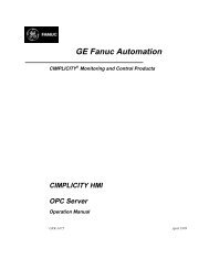
1<strong>Series</strong> <strong>90</strong>-<strong>30</strong> <strong>DeviceNet</strong> Master ModuleThe <strong>Series</strong> <strong>90</strong>-<strong>30</strong> <strong>DeviceNet</strong> Master Module (IC693DNM200) allows a <strong>Series</strong> <strong>90</strong>-<strong>30</strong> CPU to sendand receive data over a <strong>DeviceNet</strong> network. It can act as master for up to 63 slaves on the<strong>DeviceNet</strong> network. It can also be configured to simultaneously function as a slave to anothermaster on the bus.<strong>DeviceNet</strong> MasterModuleIC693DNM200NET POWERMOD STATUSNET STATUSModuleStatusLEDsDEVICENETMASTERSERVICE RS2325-IGND3-TxD2-RxDRS-232ConnectorV+CAN_HSHIELDCAN_L<strong>DeviceNet</strong>ConnectorV-DEVICENETThe module's three <strong>DeviceNet</strong>-compliant LEDs show its operating and communications status. TheRS-232 serial port (a 9-pin male D-connector) is used for a computer connection during firmwareupgrades. The <strong>DeviceNet</strong> connector is a removable spring-clamp terminal. It provides buscontinuity and can be removed from the module without disrupting bus operation.Features• Bus communications at all standard <strong>DeviceNet</strong> data rates (125k, 250k, 500k baud)• Up to 255 bytes input data transfer and 255 bytes output data transfer per slave and up to 3972bytes of input data transfer and 3972 bytes of output data transfer per master.• Unconnected Message Manager (UCMM) with 1 proxy connection per slave• One or two I/O connections plus explicit messaging can be configured for each slave. Eachslave I/O connection can be set up for one of the following: Poll, Strobe, Cyclic or Change-of-State (COS) operation. Typically one connection is used for Polled and the other is used forStrobe, Cyclic, or COS.• Independent configuration of update rates for Poll and COS/Cyclic I/O devices• Configurable global scan rate• PLC-application initiated Explicit messaging using COMMREQs• Status of communication with slaves available in the PLC fault table (configurable). Provides64 network device status bits• Configurable fault behavior on loss of communication<strong>GFK</strong>-<strong>2196</strong> Chapter 1 <strong>DeviceNet</strong> <strong>Modules</strong> for the <strong>Series</strong> <strong>90</strong>-<strong>30</strong> PLC 1-3
1<strong>Series</strong> <strong>90</strong>-<strong>30</strong> <strong>DeviceNet</strong> Master Module SpecificationsCatalog NumberDescriptionMounting LocationIC693DNM200<strong>Series</strong> <strong>90</strong>-<strong>30</strong> Master Module for <strong>DeviceNet</strong> networksAny <strong>Series</strong> <strong>90</strong>-<strong>30</strong> baseplate (CPU, expansion, or remote) slotexcept slot 1 of a modular CPU baseplateEnvironment Storage temperature: -40°C to 85°COperating temperature: 0°C to 60°CBackplane CurrentConsumptionData rates450mA at 5VDC (typical)Supports all standard <strong>DeviceNet</strong> data rates (125k, 250k, and 500kBaud)Compatibility• Compatible with any <strong>Series</strong> <strong>90</strong>-<strong>30</strong> CPU except IC693CPU321 and IC693CPU340.Configuration size is limited for CPU311/313/331, as detailed in chapter 3.• Requires release 8.0 CPU firmware. Release 10 is recommended, if available for a particularCPU.• Requires CIMPLICITY Machine Edition Logic Developer PLC version 3.0 with Service Packfor <strong>DeviceNet</strong>, or later.• Not compatible with the VersaPro, Control, or Logicmaster programming software.• The <strong>Series</strong> <strong>90</strong>-<strong>30</strong> Hand-Held Programmer (IC693PRG<strong>30</strong>0) cannot be used to configure thismodule.1-4 <strong>Series</strong> <strong>90</strong>®-<strong>30</strong> Programmable Controller <strong>DeviceNet</strong> <strong>Modules</strong> – November 2002 <strong>GFK</strong>-<strong>2196</strong>
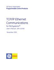
1<strong>Series</strong> <strong>90</strong>-<strong>30</strong> <strong>DeviceNet</strong> Slave ModuleThe <strong>Series</strong> <strong>90</strong>-<strong>30</strong> <strong>DeviceNet</strong> Slave Module (IC693DNS201) interfaces a <strong>Series</strong> <strong>90</strong>-<strong>30</strong> PLC to a<strong>DeviceNet</strong> bus that is controlled by another master device.<strong>DeviceNet</strong>Slave ModuleNET POWERMOD STATUSNET STATUSModuleStatusLEDsDEVICENETSLAVESERVICE RS2325-IGND3-TxD2-RxDRS-232ConnectorV+CAN_HSHIELDCAN_L<strong>DeviceNet</strong>ConnectorV-DEVICENETThe module's three <strong>DeviceNet</strong>-compliant LEDS show its operating and communications status. TheRS-232 serial port (a 9-pin male D-connector) is used for a computer connection during firmwareupgrades. The <strong>DeviceNet</strong> connector is a removable spring-clamp terminal. It provides buscontinuity and can be removed from the module without disrupting bus operation.Features• Bus communications at all standard <strong>DeviceNet</strong> data rates (125k, 250k, 500k baud)• Up to 255 bytes input data transfer and 255 bytes output data transfer.• Configurable for Poll, Strobe, Cyclic and COS I/O Connections, and Explicit Messaging• Supports Unconnected Message Manager (UCMM) allowing up to 250 simultaneous explicitmessaging connections.• One or two I/O connections plus explicit messaging can be configured. Each I/O connectioncan be set up for one of the following: Poll, Strobe, Cyclic or Change-of-State (COS)operation. Typically one connection is used for Polled and the other is used for Strobe, Cyclic,or COS.• Supports the Assembly Object and access to the input and output data for each of theconfigured slave I/O areas (I/O Area 1 and I/O Area 2) with the SET_ATTRIBUTE_SINGLEand GET_ATTRIBUTE_SINGLE services. Up to 255 bytes of attribute data may be suppliedin the SET_ATTRIBUTE_SINGLE operation.• Configurable fault behavior on loss of communication.• UCMM-capable Group 2 Server<strong>GFK</strong>-<strong>2196</strong> Chapter 1 <strong>DeviceNet</strong> <strong>Modules</strong> for the <strong>Series</strong> <strong>90</strong>-<strong>30</strong> PLC 1-5
1<strong>Series</strong> <strong>90</strong>-<strong>30</strong> <strong>DeviceNet</strong> Slave Module SpecificationsCatalog NumberDescriptionMounting LocationIC693DNS201<strong>Series</strong> <strong>90</strong>-<strong>30</strong> Slave Module for <strong>DeviceNet</strong> networksAny <strong>Series</strong> <strong>90</strong>-<strong>30</strong> baseplate (CPU, expansion, or remote)slot except slot 1 of a modular CPU baseplateEnvironment Storage temperature: -40°C to 85°COperating temperature: 0°C to 60°CBackplane CurrentConsumption450mA at 5VDC (typical)Compatibility• Compatible with any <strong>Series</strong> <strong>90</strong>-<strong>30</strong> CPU except IC693CPU321 and IC693CPU340.• Requires release 8.0 CPU firmware. The latest Release 10 is recommended, if availablefor the particular CPU.• Requires CIMPLICITY Machine Edition Logic Developer PLC version 3.0 with ServicePack for <strong>DeviceNet</strong>, or later.• Not compatible with the VersaPro, Control, or Logicmaster programming software.• The <strong>Series</strong> <strong>90</strong>-<strong>30</strong> Hand-Held Programmer (IC693PRG<strong>30</strong>0) cannot be used to configurethis module.1-6 <strong>Series</strong> <strong>90</strong>®-<strong>30</strong> Programmable Controller <strong>DeviceNet</strong> <strong>Modules</strong> – November 2002 <strong>GFK</strong>-<strong>2196</strong>
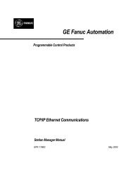
1The <strong>DeviceNet</strong> Network<strong>DeviceNet</strong> is a communications network that transmits data between control systems (for example:PLCs, PCs, VMEbus computers, and robot controllers) and distributed industrial devices such asswitches, sensors, valve manifolds, motor starters, bar code readers, drives, displays, and operatorinterfaces. The network can also link intelligent interface modules such as the VersaPoint<strong>DeviceNet</strong> Network Interface Unit (NIU) and the VersaMax <strong>DeviceNet</strong> NIU. An NIU is thenetwork interface for an I/O Station of many additional modules.The <strong>DeviceNet</strong> network has a linear structure. There is a main trunk line with drop lines routed tothe networked devices. Power and signals are carried on the same network cable. A <strong>Series</strong> <strong>90</strong>-<strong>30</strong><strong>DeviceNet</strong> module can be connected directly to the trunk cable or installed as an individual drop oras part of a daisy-chain drop.Master<strong>Series</strong> <strong>90</strong>-<strong>30</strong> PLC with<strong>DeviceNet</strong> Master ModuleSlaves<strong>Series</strong> <strong>90</strong>-<strong>30</strong> PLCwith <strong>DeviceNet</strong> SlaveModule<strong>GFK</strong>-<strong>2196</strong> Chapter 1 <strong>DeviceNet</strong> <strong>Modules</strong> for the <strong>Series</strong> <strong>90</strong>-<strong>30</strong> PLC 1-7
1<strong>DeviceNet</strong> Communications for <strong>Series</strong> <strong>90</strong>-<strong>30</strong> <strong>DeviceNet</strong> <strong>Modules</strong><strong>DeviceNet</strong> uses the Producer-Consumer technique of messaging. A device with data produces thedata on the network. All devices that need data listen for messages. When a device recognizes theappropriate identifier, it consumes the data. A message is not specific to a particular source ordestination, and one message can be consumed by multiple devices. For example, one messagecould control several motor starter modules.A <strong>DeviceNet</strong> message field can range between 0 and 8 bytes. Messages longer than 8 bytes arefragmented into packets. The <strong>Series</strong> <strong>90</strong>-<strong>30</strong> <strong>DeviceNet</strong> modules assure data integrity for eachnetwork node.I/O MessagingI/O messaging is used for the routine and automatic exchange of data between devices. IndividualI/O messages can be up to 255 bytes in length. I/O messages provide a dedicated communicationpath between a producing device and one or more consuming devices. System configuration sets upthe parameters for the connections between the producing and consuming devices. With theconnections established, communications occur automatically.There are four basic types of I/O messages: Polled, Strobed, Cyclic, and Change-of-State (COS).The <strong>Series</strong> <strong>90</strong>-<strong>30</strong> <strong>DeviceNet</strong> Master Module can be configured for up to two different types of I/Omessaging connections to each slave (for example, one Cyclic I/O messaging connection and oneChange-of-State I/O messaging connection). See chapter 3, "PLC Configuration for the DeviceMetMaster" for details.Explicit MessagingExplicit messaging provide a point-to-point communication link between two devices on thenetwork. Explicit messaging is often used for slave configuration and for diagnostics. SpecificExplicit messages are defined for the <strong>DeviceNet</strong> protocol. For the <strong>Series</strong> <strong>90</strong>-<strong>30</strong> <strong>DeviceNet</strong> Mastermodule, Communications Request (COMMREQs) are used to send Explicit messages. See chapter6, "Programmed Communications" for more information. Received Explicit messages areautomatically processed by the <strong>DeviceNet</strong> module except for user defined Objects which requireuser programmed COMMREQs support.1-8 <strong>Series</strong> <strong>90</strong>®-<strong>30</strong> Programmable Controller <strong>DeviceNet</strong> <strong>Modules</strong> – November 2002 <strong>GFK</strong>-<strong>2196</strong>
Chapter2InstallationThis chapter provides basic installation information for the <strong>Series</strong> <strong>90</strong>-<strong>30</strong> <strong>DeviceNet</strong> <strong>Modules</strong>:• Power requirements: PLC system power and <strong>DeviceNet</strong> network power• The <strong>DeviceNet</strong> cable: specifications, length, termination, taps• Grounding: <strong>DeviceNet</strong> cable, <strong>DeviceNet</strong> power supply, <strong>DeviceNet</strong> system• Installing the <strong>DeviceNet</strong> module in the PLC• The Module LEDs: Module Status, Network Status, Network Power• The RS-232 Serial PortFor Additional InformationCorrect installation of cables, power supplies, and other network hardware requires a more detailedknowledge of <strong>DeviceNet</strong> specifications than can be provided here. Readers are referred towww.ODVA.org for additional information.Conformance to StandardsBefore installing GE Fanuc products in situations where compliance to standards or directives fromthe Federal Communications Commission, the Canadian Department of Communications, or theEuropean Union is necessary please refer to GE Fanuc’s Installation Requirements forConformance to Standards, <strong>GFK</strong>-1179.<strong>GFK</strong>-<strong>2196</strong> 2-1
2Power SuppliesWhen using a <strong>Series</strong> <strong>90</strong>-<strong>30</strong> <strong>DeviceNet</strong> module, there are two separate power supplies to consider:the PLC power supply and the <strong>DeviceNet</strong> network power supply.PLC PowerA <strong>Series</strong> <strong>90</strong>-<strong>30</strong> <strong>DeviceNet</strong> module consumes 450mA at 5VDC (typical) from the PLC backplane.A high-capacity <strong>Series</strong> <strong>90</strong>-<strong>30</strong> power supply such as IC693PWR3<strong>30</strong> or IC693PWR331 isrecommended when using these modules, especially for CPU models CPU350 or higher, or if thePLC includes Ethernet adapters and/or multiple <strong>DeviceNet</strong> modules.The PLC power supply load is automatically calculated by the CIMPLICITY Machine Editionconfiguration software. Additional information about estimating power supply load can be foundin <strong>GFK</strong>-0356, the <strong>Series</strong> <strong>90</strong>-<strong>30</strong> Installation and Hardware <strong>Manual</strong>.<strong>DeviceNet</strong> PowerThe <strong>Series</strong> <strong>90</strong>-<strong>30</strong> <strong>DeviceNet</strong> modules power their network transceivers from the 24VDC <strong>DeviceNet</strong>network power source. Linear power supplies are recommended for the <strong>DeviceNet</strong> power source.The <strong>DeviceNet</strong> power source should not also be used for device power. Transients caused by I/Odevices can cause communications errors and even create bus-off conditions.The <strong>DeviceNet</strong> specification recommends using a power tap to connect a power supply to thenetwork. The power tap should be appropriately fused for the current capacity of the bus cables.The maximum current on the network depends on the cable type.The <strong>Series</strong> <strong>90</strong>-<strong>30</strong> <strong>DeviceNet</strong> modules consume xxxma at 24VDC (typical) from the <strong>DeviceNet</strong>Network.Current Limit for Thick CableFor thick cable, the maximum current on the network is 16 Amps. However, only 8 Amps ispermitted on a single network segment. 16 Amps can be drawn from a single power supply bylocating the power supply at the center point of two network segments, supplying 8 Amps to eachsegment.Current Limit for Thin CableFor thin cable, the maximum current permitted is 3 Amps.2-2 <strong>Series</strong> <strong>90</strong>®-<strong>30</strong> Programmable Controller <strong>DeviceNet</strong> <strong>Modules</strong> – November 2002 <strong>GFK</strong>-<strong>2196</strong>
2<strong>DeviceNet</strong> Cable for the <strong>Series</strong> <strong>90</strong>-<strong>30</strong> <strong>Modules</strong><strong>Series</strong> <strong>90</strong>-<strong>30</strong> <strong>DeviceNet</strong> modules can be used with the either <strong>DeviceNet</strong> thick cable or thin cable.Thick cable permits greater cable lengths and higher current levels. Generally, thick cable is usedfor the trunk cable. Thin cable is normally used for shorter distances and is suitable for drop cablesand for installations where more cable flexibility is needed.Both thick cable and thin cable are 5-wire, multi-conductor copper cable. Two wires form atransmission line for network communications. A second pair transmits network power. The fifthconductor forms an electromagnetic shield. Most cables have color coded leads which correspondto the color coding on the terminals on the <strong>Series</strong><strong>90</strong>-<strong>30</strong> <strong>DeviceNet</strong> modules.Cable and Network SpecificationsThick Cable General SpecificationsThin Cable General SpecificationsTwo shielded pairs - Common axis with drain wire in centerOverall braid shield - 65% coverage; 36 AWG or 0.12mm tinned Cubraid minimum (individually tinned)Drain wire- #18 Copper min.; 19 strands minimum (individually tinned)Outside diameter - 0.410 inches (min) to 0.4<strong>90</strong> inches (max.) roundness- radius delta to be within 15% of 0.5 O.D.Two shielded pairs - Common axis with drain wire in centerOverall braid shield - 65% coverage; 36 AWG or 0.12mm tinned Cubraid minimum (individually tinned)Drain wire - #22 Copper; 19 strands minimum (individually tinned)Outside diameter - 0.240 inches (min.) to 0.280 inches (max.)roundness - radius delta to be within 20% of 0.5 O.D.Network TopologyBus with limited branching (trunkline/dropline)RedundancyNot SupportedNetwork Power for Node devices Nominal 24 VDC ±4%Allowed Nodes (Bridging excluded)Data Packet SizeDuplicate Address DetectionError Detection / Correction64 nodes0-8 bytes with allowance for message fragmentationAddresses verified at power-upCRC - retransmission of message if validity not acknowledged byrecipientBus Connector Pin AssignmentsThe <strong>DeviceNet</strong> connector on a <strong>Series</strong> <strong>90</strong>-<strong>30</strong> <strong>DeviceNet</strong> module has five color-coded screw-clampterminals. The connector provides bus continuity; it can be removed from the module withoutdisrupting bus operation.V+CAN_HSHIELDCAN_LV-Signal Pin Wire ColorV+ 5 RedCAN_H 4 WhiteShield 3 BareCAN_L 2 BlueV- 1 Black<strong>GFK</strong>-<strong>2196</strong> Chapter 2 Installation 2-3
2Bus LengthThe maximum length of the trunk cable and drops both depend on the cable type and data rate.Individual drops may not exceed 6 meters and are limited to one network node per drop. However,the node may have multiple ports.Data Rates 125kbps 250kbps 500kbpsthick cable, trunk length 500m (1640ft) 250m (820ft) 100m (328ft)thin cable, trunk length 100m (328ft) 100m (328ft) 100m (328ft)maximum drop length 6m (20ft) 6m (20ft) 6m (20ft)total length of all drops 156m (512ft) 78m (256ft) 39m (128ft)For each baud rate, the total drop length is the sum of all the drop lines of both cable types in thenetwork.In addition, if the distance from a tap to the most distant device on its drop is longer than thedistance from the tap to the nearest terminating resistor as illustrated below, the drop line lengthalso counts as part of the trunk cable length (as well as the overall drop length).Distance toTerminatingResistorTapTerminatingResistorNodeLongestDistanceto a NodeNodeNode2-4 <strong>Series</strong> <strong>90</strong>®-<strong>30</strong> Programmable Controller <strong>DeviceNet</strong> <strong>Modules</strong> – November 2002 <strong>GFK</strong>-<strong>2196</strong>
2Network Termination121 Ohm, 1% ¼ watt terminating resistors MUST be installed at both ends of the <strong>DeviceNet</strong>network. Each terminating resistor is placed across the data communication signals at pin 2(CAN_L) and pin 4 (CAN_H).Taps, Daisy-Chaining and BranchesDevices can be connected directly to the trunk cable, or to drop lines that are joined to the trunkcable with taps. Taps can be mounted in junction boxes or panels. Drop lines and daisy-chains areoften used inside control panels where multiple devices are grouped together. When using dropswith daisy-chains and branches, the maximum length from a tap to its farthest drop is 20 feet.TapTrunk LineTapNode Node NodeNodeNodeNodeDrop LinesNodeNodeNodeWiring to the <strong>Series</strong> <strong>90</strong>-<strong>30</strong> <strong>DeviceNet</strong> Master module depends on its location on the network:If the <strong>Series</strong> <strong>90</strong>-<strong>30</strong> <strong>DeviceNet</strong>module is located at either endof the bus trunk, it is wired withone cable connection and aterminating resistor:If the module is installed at theend of a drop or drop segment,it is wired with one cableconnection only.If the module is installeddirectly on the trunk cable or aspart of a daisy-chained dropcable, it has both an incomingand outgoing cable connected:<strong>GFK</strong>-<strong>2196</strong> Chapter 2 Installation 2-5
2Grounding<strong>DeviceNet</strong> Cable GroundingAll <strong>DeviceNet</strong> cable shields must be tied to ground at each device connection. This is done bytying the bare wire of the cable to pin 3 (Shield) of the connector.<strong>DeviceNet</strong> Power Supply GroundingThe <strong>DeviceNet</strong> network power supply must also be grounded, but only at one point. The V- signalmust be connected to protective earth ground at the power supply only. If multiple power suppliesare used, only one power supply must have V- connected to earth ground.<strong>DeviceNet</strong> System Grounding<strong>DeviceNet</strong> communications should only be grounded to earth at a single point. Typically this isdone in the control cabinet where the <strong>DeviceNet</strong> power supply is located.Return for the <strong>DeviceNet</strong> power (-V), the drain (bare wire) and the cable shields must be directlytied to earth ground. Ideally, this grounding is done at a central location. Connection should bemade using a 25mm (1in.) copper braid or a #8 AWG wire not longer than 3meters (10ft.).The illustration below represents grounding for a network that has two power supplies. The chassisof each power supply is connected to earth ground.Power Supply #1 Power Supply #2Return+24V Return +24VV+CAN_HSHIELDCAN_LV-Ground Wire SizeThe minimum size ground conductor for the <strong>DeviceNet</strong> screw-clamp terminals on a <strong>Series</strong> <strong>90</strong>-<strong>30</strong><strong>DeviceNet</strong> module is a 2.5mm 2 (14 AWG) wire. For other network devices, larger wire diametersmay be necessary.2-6 <strong>Series</strong> <strong>90</strong>®-<strong>30</strong> Programmable Controller <strong>DeviceNet</strong> <strong>Modules</strong> – November 2002 <strong>GFK</strong>-<strong>2196</strong>
2Installing the <strong>DeviceNet</strong> Module in the PLC RackA <strong>Series</strong> <strong>90</strong>-<strong>30</strong> <strong>DeviceNet</strong> module can be installed in the main (CPU) rack in slot 2 or higher, or inslot 1 or higher of any expansion rack.1. Turn off power to the rack.2. Place the module into its slot by hooking the top of the module on the notch above the slot andslowly lowering the module until it snaps into place.3. Attach the <strong>DeviceNet</strong> cable to the module.4. Terminate the network as required.Note: For details about installing <strong>Series</strong> <strong>90</strong>-<strong>30</strong> rack systems and modules, refer to the <strong>Series</strong><strong>90</strong>-<strong>30</strong> Installation <strong>Manual</strong> and Hardware <strong>Manual</strong>, <strong>GFK</strong>-0356.Removing the Module from the RackTo remove the module from the rack:1. Turn off power to rack.2. Remove all cables from the module.3. Press the release located on the bottom of the module and slowly raise the module fromthe bottom until it comes out of the slot.<strong>GFK</strong>-<strong>2196</strong> Chapter 2 Installation 2-7
2Module LEDsThe module's three LEDs show its operating and communications status:NET POWERMOD STATUSNET STATUSNetwork Power LEDLEDRedGreenIndicatesThere is no power detected on the network.Power detected on the network.Module Status LEDLEDOffGreenFlashingGreenFlashing RedRedFlashing Red/ GreenIndicatesThere is no backplane power to the module.The module is operating normally.The module is in standby mode. Its configuration is missing, incomplete,or incorrect. The module may be in Standby state.Recoverable FaultThe module has an unrecoverable fault; it may need resetting orreplacing.The module is in Self Test mode.Network Status LEDLEDIndicatesOff • The module is not online, or• The module has not completed the Duplicate MACID test, or• The module may not be powered. See Module Status LED.FlashingGreenGreenFlashing RedRedFlashing Red/ Green• The module is online but has no connections in the establishedstate, or• The module has passed the Duplicate MACID check, is online, buthas no established connections with other nodes.The module is online and has one or more connections in theestablished state.One or more I/O Connections are in the Timed Out state.The module is not capable of communicating on the network.The module has detected a Network Access error and is in theCommunication Faulted State.2-8 <strong>Series</strong> <strong>90</strong>®-<strong>30</strong> Programmable Controller <strong>DeviceNet</strong> <strong>Modules</strong> – November 2002 <strong>GFK</strong>-<strong>2196</strong>
2RS-232 Serial PortThe RS-232 serial port is a 9-pin male D-connector. This port is used for a computer connectionduring firmware upgrades.SERVICE RS2325-IGND3-TxD2-RxDUpgrading the <strong>DeviceNet</strong> Module's FirmwareWhen future upgrades to the firmware are made available, the module can be upgraded asdescribed below.1. Download the firmware upgrade to the computer that will be used to perform the upgrade.Firmware upgrades are usually available from the GE Fanuc WEB sitewww.gefanuc.com/support/plc/2. Connect a straight through serial cable from the computer to the serial port on the front of the<strong>DeviceNet</strong> module. Only the RX and TX lines are used. The cable that is part of the RS232 toRS485 kit (IC693ACC<strong>90</strong>3) is suitable.3. The computer can utilize any standard communication software to communicate with themodule. The module supports 19200 baud, no parity, 8 data bits, 1 stop bit, and no flowcontrol.4. Cycle power to the <strong>Series</strong> <strong>90</strong>-<strong>30</strong> PLC rack that contains the <strong>DeviceNet</strong> module.5. At the computer, press ENTER until you see the initial greeting. The greeting indicates that theboot code is waiting for new firmware. Initiate an Xmodem send of the module firmware fileusing your communication software. Note: You must press the ENTER key immediately afterthe power is cycled. It is recommended you hold down the ENTER key when turning thepower back on.6. When it finishes successfully storing the new firmware, the module automatically resets andattempts to start the new firmware.7. If the firmware transfer was not successful, the greeting screen reappears. Retry the transfer.On success, disconnect the serial cable and cycle power to the <strong>Series</strong> <strong>90</strong>-<strong>30</strong> PLC rack.<strong>GFK</strong>-<strong>2196</strong> Chapter 2 Installation 2-9
Chapter3PLC Configuration for the <strong>DeviceNet</strong> MasterThis chapter explains how to add a <strong>Series</strong> <strong>90</strong>-<strong>30</strong> <strong>DeviceNet</strong> Master Module (IC693DNM200) to theconfiguration of the <strong>Series</strong> <strong>90</strong>-<strong>30</strong> PLC. It also explains how to configure communicationsconnections between a <strong>Series</strong> <strong>90</strong>-<strong>30</strong> <strong>DeviceNet</strong> Master Module and the <strong>DeviceNet</strong> network.• Configuration Steps• Adding a <strong>DeviceNet</strong> Master Module to the PLC Configuration• Configuring the Parameters of a <strong>DeviceNet</strong> Master Module• Parameters of a <strong>DeviceNet</strong> Master Module• Network Settings of a <strong>DeviceNet</strong> Master Module• Telling the <strong>DeviceNet</strong> Master about Slaves by Adding Slaves to the Network• Adding a Device's EDS File• Configuring Network Settings for Slaves Added to the Master• Assigning the MAC IDs and Baud Rate• Configuring I/O Messaging Connections• Configuring <strong>DeviceNet</strong> Explicit Messaging• Configuring Network Settings for a <strong>DeviceNet</strong> Master Acting as a Slave• Assigning the MAC IDs and Baud Rate• Configuring I/O Messaging Connections for a <strong>DeviceNet</strong> Master Acting as a Slave• Configuring <strong>DeviceNet</strong> Explicit MessagingThese configuration procedures are written for users who have a basic knowledge of theCIMPLICITY Machine Edition Logic Developer software and the <strong>Series</strong> <strong>90</strong>-<strong>30</strong> PLC. For helpwith using the software, please see the software’s built-in help system.Note:The <strong>DeviceNet</strong> Master is only supported in CIMPLICITY Machine Edition LogicDeveloper. The Logicmaster, VersaPro, and Control software do not support these<strong>Series</strong> <strong>90</strong>-<strong>30</strong> <strong>DeviceNet</strong> modules.<strong>GFK</strong>-<strong>2196</strong> 3-1
3Configuration StepsThere are three basic steps to configuring a <strong>Series</strong> <strong>90</strong>-<strong>30</strong> <strong>DeviceNet</strong> Master Module:• Adding the module to the PLC rack and configuring its operating parameters.• Telling the <strong>DeviceNet</strong> Master about slaves by adding the network slaves to the Master andconfiguring their network settings.The number and type of slave devices and the amount of data they can exchange with themaster may be limited by the CPU memory available. The amount of CPU memory availablefor the <strong>DeviceNet</strong> configuration depends on: the CPU model being used, the version of theCPU firmware, the number and type of other modules in the configuration, the number andtype of slave devices configured, and the amount and type of communication in progress withan external programmer or HMI devices. With Logic Developer-PLC, the size of the currentconfiguration can be read by selecting “Data View” for the hardware configuration and addingthe sizes of the components listed. LD-PLC will not allow configurations to be created thatexceed 65,535 bytes. The size of the <strong>DeviceNet</strong> configuration is also limited by the size of theuser configuration space for the models listed below:CPU 311/313CPU 3314,736 bytes available4,673 bytes available• (Optional) Configuring the network settings of the <strong>DeviceNet</strong> Master Module itself. This isONLY done if the <strong>DeviceNet</strong> Master Module will also operate as a server to another networkmaster. For example, it might exchange data relating to the operation of its slaves with ahigher-level host controller.3-2 <strong>Series</strong> <strong>90</strong>®-<strong>30</strong> Programmable Controller <strong>DeviceNet</strong> <strong>Modules</strong> – November 2002 <strong>GFK</strong>-<strong>2196</strong>
3Adding a <strong>DeviceNet</strong> Master Module to the PLC ConfigurationFirst, add the <strong>Series</strong> <strong>90</strong>-<strong>30</strong> <strong>DeviceNet</strong> Master Module (IC693DNM200) to the PLC rackconfiguration. The module is compatible with any <strong>Series</strong> <strong>90</strong>-<strong>30</strong> CPU except IC693CPU321 orIC693CPU340. It requires release 8.0 CPU firmware as a minimum. Release 10.6 or later isrecommended, if available for your particular CPU.1. In that configuration, in the Project tab of the Navigator, expand the Hardware Configurationfolder.2. In the Hardware Configuration folder, right click the intended PLC Slot for the <strong>DeviceNet</strong>Master Module. It can be any slot except slot 1 of a modular CPU rack.3. Select Add Module from the shortcut menu.HardwareConfiguration FolderNavigator WindowShort Cut MenuThe Module Catalog dialog box appears.4. To add a <strong>DeviceNet</strong> Master Module, click on the Bus Controller tab. The Bus Controllermodule list appears. Select IC693DNM200 <strong>DeviceNet</strong> Master from the list and click OK.<strong>GFK</strong>-<strong>2196</strong> Chapter 3 PLC Configuration for the <strong>DeviceNet</strong> Master 3-3
3Configuring the Parameters of a <strong>DeviceNet</strong> Master ModuleThe <strong>DeviceNet</strong> Master Module is added to the PLC configuration in the Navigator window, and themodule’s Parameter Editor window appears in the InfoViewer window space.Parameters of a <strong>DeviceNet</strong> Master ModuleSettings tabMac IDSlave Status BitArray AddressLength(of slave statusbits)NetworkStatus/FirmwareID AddressLength (ofnetwork status/firmware ID)Program ModeTransmissionThe Mac ID (medium access control identification) of the master on the <strong>DeviceNet</strong> network.Valid range: 0 - 63. Default: 0.The starting address for an array of bits indicating the health of each node on the<strong>DeviceNet</strong> network. It must be a non-overlapping range in %AI, %I, %Q, %G, %AQ, %R,%T, or %M. It defaults to %I memory and uses the next available %I address.A slave's status address equals Start Address + Station Address of the slave. For example,if the status bits are mapped to %I00001, the status for the slave at Station Address 5would be found at %I00001 + 5 = %I00006.The master’s status is located in the same way as the slaves’ (Start Address + StationAddress). The master is configured as station 0 by default, but can be set to any validaddress (0-64).(Read-only.) Length has a value of 64, corresponding to 64 network devices.The starting address for three words of module/network status information. The default is%AI memory and uses the next available %AI address. The Network Status/Firmware IDAddress must be a non-overlapping range in %AI, %I, %Q, %G, %AQ, %R, %T, or %M.During system operation, the module and network status data and module firmware ID willbe stored in this memory location.(read only) Length of the Network Status / Firmware ID Address memory location, 3 words.When the PLC is in Program mode (Stop mode), the <strong>DeviceNet</strong> Master Module can eithersend idle packets or set data to zero. The default is to send idle packets.3-4 <strong>Series</strong> <strong>90</strong>®-<strong>30</strong> Programmable Controller <strong>DeviceNet</strong> <strong>Modules</strong> – November 2002 <strong>GFK</strong>-<strong>2196</strong>
3Settings tabFault StateTransmissionInputs on Lossof SlaveSlave StatusFault TableEntriesAck Timeout(ms)Baud Rate(kbps)Scan Interval(ms)for StrobedconnectionsReconnect Time(ms)DownloadNames &DescriptionsDownload EDSFilesWhen the <strong>DeviceNet</strong> Master Module detects a PLC fault (because the PLC has notrequested its regular I/O update from the module), the module can either send idle packetsor set data to zero. The default is to send idle packets.If the <strong>DeviceNet</strong> Master loses communications with a slave, it can hold the module's inputreported to the CPU in its last state (the default), or clear the input data.When slave communications status events (loss and re-establish) occur, the <strong>DeviceNet</strong>Master Module can either report them in the fault table or not. If this setting is True (thedefault), the Master makes fault table entries. If this setting is False, slave status eventsare not reported to the fault table.Number of milliseconds to wait for a CAN Acknowledge of the Duplicate MacID check(performed during startup) before reporting an Ack (acknowledge) failure. Valid range: 0 to65,535. The default is 2,000ms (2 seconds).The data transmission rate for the <strong>DeviceNet</strong> Master Module. The maximum baud rate thatcan be used depends on the bus length and cable type. See chapter 2 for moreinformation. Choose: 125K, 250K, or 500K.The time interval between successive scans of Strobed slave connections. This defaults tozero. A time must be specified if any slave connections are set up for strobing. The validrange is 0 to 65,535ms. All strobed connections will be scanned at this same interval.If a slave fails to respond to three consecutive scan cycles, the slave is flagged as notpresent and the master tries to reconnect to it.This parameter specifies how long the master should wait before attempting to reconnect.The default time is 0. The valid range is 100 to 65535ms.This setting determines whether or not names and descriptions that have been use in theconfiguration will be downloaded to the PLC when the configuration is downloaded.By default, this parameter is False and names and descriptions are not downloaded to thePLC. This is the recommended choice because downloaded names and descriptions cantake up too much memory in the PLC. Names and descriptions are a convenience only.Omitting them from the download does not affect system operation. However, if thisparameter is set to False, later uploads of the configuration from the PLC to theprogrammer will contain only default names and descriptions.If this parameter is set to True, names and descriptions that have been entered for theslaves and the master are downloaded to the PLC and will be present in the configuration ifit is uploaded to the programmer later..This setting determines whether or not the EDS files that have been used for theconfiguration will be downloaded from the programmer to the PLC when the configurationis downloaded.By default, this parameter is False and EDS files are not downloaded to the PLC. This isthe recommended choice, because downloaded EDS files can consume too much memoryin the PLC. However, when this is set to False, if the configuration is later uploaded fromthe PLC back to the programmer, it will not contain the EDS files. You would need anothersource for the EDS files (for example, on disk) to configure more modules of a given type.If the EDS files are no longer available, it is only possible to add more modules of that typeas generic modules.If this parameter is set to True, the EDS files are included when the configuration isdownloaded to the PLC. If the configuration is later uploaded back to the programmer, theEDS files will be restored to the Toolchest for use by the configuration.<strong>GFK</strong>-<strong>2196</strong> Chapter 3 PLC Configuration for the <strong>DeviceNet</strong> Master 3-5
3Data Areas TabThis tab shows the PLC program references assigned to the <strong>DeviceNet</strong> MasterModule's Network Settings when it is used as a slave:This TAB is optional and should only be used when the <strong>DeviceNet</strong> MasterModule is also a slave to another Devicenet master device.Note: Do not enter values on this tab if the <strong>DeviceNet</strong> Master Module is notalso used as a slave. Entering values on this tab when the <strong>DeviceNet</strong> Master isnot used as a slave causes the <strong>DeviceNet</strong> Master to fail to communicate withslaves.Power Consumption TabPower consumptionThis read-only tab shows the backplane power that will be consumed by the<strong>DeviceNet</strong> Slave Module. This power will be used for module operation.The <strong>DeviceNet</strong> Slave Module also draws power for its <strong>DeviceNet</strong> transceiverfrom the 24VDC power supply on the <strong>DeviceNet</strong> network.3-6 <strong>Series</strong> <strong>90</strong>®-<strong>30</strong> Programmable Controller <strong>DeviceNet</strong> <strong>Modules</strong> – November 2002 <strong>GFK</strong>-<strong>2196</strong>
3Network Settings of a <strong>DeviceNet</strong> Master ModuleTo configure the Network Settings for a <strong>DeviceNet</strong> Master Module, right-click the <strong>DeviceNet</strong>Master in the PLC configuration, and choose Network Settings:The Network Settings dialog box appears.The General tab allows setting a name and description for the module. On this tab, you can alsoselect the MACID, Baud Rate, Scan Interval, and Reconnect Time. These parameters are alsofound on the Configuration Parameter screen; they can be set in either place.The rest of the tabs are only used if the <strong>Series</strong> <strong>90</strong>-<strong>30</strong> <strong>DeviceNet</strong> Master Module will operate as aserver (slave) to another master on the network. If the <strong>DeviceNet</strong> Master is not a slave to another<strong>DeviceNet</strong> master these three tabs should be left blank. Please turn to “Configuring NetworkSettings” later in this chapter for detailed information about the Network Setting parameters.<strong>GFK</strong>-<strong>2196</strong> Chapter 3 PLC Configuration for the <strong>DeviceNet</strong> Master 3-7
3Telling the <strong>DeviceNet</strong> Master about Slaves by Adding Slaves to theNetworkAfter adding the <strong>DeviceNet</strong> Master Module to the PLC rack, you need to tell the Master about therequired communication to the slave devices on the <strong>DeviceNet</strong> network by adding slaves to theMaster. There are two ways to add a slave to the network configuration:• In the Navigator window, right-click on the IC693DNM200 Master Module and choose AddSlave.Select the slave type from the list that appears. Click OK to select the slave. For example, toadd a <strong>Series</strong> <strong>90</strong>-<strong>30</strong> <strong>DeviceNet</strong> Slave Module (IC693DNS201) as a slave on the network, youwould select:• You can also drag and drop a device from the Toolchest to the <strong>DeviceNet</strong> master. Open theToolchest by clicking the Toolchest button on the Tools toolbar. Select the <strong>DeviceNet</strong> Devicesdrawer. Choose a slave device.If you are editing a configuration that was uploaded from the PLC, the presence of device EDSfiles (and also device names and descriptions) depends on the <strong>DeviceNet</strong> Master Moduleconfiguration, as described earlier in this chapter. If the EDS files and names and descriptionswere not downloaded, they will not be part of the uploaded configuration, and the EDS filesmay no longer be present in the Toolchest.Whether you are adding devices in the Navigator or using the drag and drop method , if youdon't see the type of device you want to add and also don't have an EDS file for the device, youcan only configure the slave as a generic device .Adding a Device's EDS FileIf the device you want to configure is not listed and is not in the Toolchest, you can provide theEDS file, which is supplied by the device manufacturer, by clicking Have Disk. In the Open dialogbox, browse to the EDS file and click Open. (When you select an EDS file using this method, it isadded to the Slave Catalog and the <strong>DeviceNet</strong> Devices drawer of the Toolchest.)3-8 <strong>Series</strong> <strong>90</strong>®-<strong>30</strong> Programmable Controller <strong>DeviceNet</strong> <strong>Modules</strong> – November 2002 <strong>GFK</strong>-<strong>2196</strong>
3Configuring Network Settings for Slaves Added to the MasterThe Network Settings include MAC IDs, baud rates, and the messaging connections betweendevices on the network.Assigning the MAC IDs and Baud RateBe sure the MAC IDs entered for slaves in the Machine Edition configuration match the MAC IDsset up for the devices themselves.Many devices have their MAC IDs set by DIP switches. Some have their MAC IDs set byconfiguration commands from the master. All software-configured devices originally have thesame default MAC ID: 63. To configure a software configured device, add a generic device withMACID 63 and enable Explicit Messaging to allow the configuration message to be sent to thedevice. Therefore, assigning the MAC ID 63 to be used by a device on the network should be donecarefully, to prevent duplicate MAC ID conflicts when adding a new slave. Because all softwareconfigurableslaves originally have the same default MAC ID, such slaves should be connected tothe network one at a time. As each new slave is connected, its MAC ID should be changed using aSend Device Explicit COMMREQ, and its operation should be checked before connecting the nextslave. Remember that the device will take on the new MAC ID after the configuration message issent to it.Configuring the MAC ID of a Slave DeviceOn the Network Settings: General tab, configure the device's MAC ID. The MAC ID will default tothe next available address but will not fill in skipped addesses.The dropdown list displays MACIDs that have not been used in the Machine Edition configuration. In this example, IDs 2 and 3have already been assigned, so those numbers do not appear in the list.NameA field is provided to give the slave an identifying nameDescriptionA field is provide to add a description of the slave<strong>GFK</strong>-<strong>2196</strong> Chapter 3 PLC Configuration for the <strong>DeviceNet</strong> Master 3-9
3Configuring I/O Messaging Connections for Slaves added to the MasterI/O Messaging is the term used for the routine and automatic exchange of data between the masterand slaves in a <strong>DeviceNet</strong> system. Each configured I/O Message defines a dedicatedcommunication path between a producing device and one or more consuming devices. Once theseconnections have been established, I/O Messaging communications occur automatically duringsystem operation.Each <strong>Series</strong> <strong>90</strong>-<strong>30</strong> device in a <strong>DeviceNet</strong> system can be set up for up to two different I/OMessaging connections. Each connection can be disabled (the default), or set up for Polled,Strobed, Change-of-State, or Cyclic operation. Connections should be configured to meet the needsof the application. For example, the master might Strobe all the input-only slave devices and Pollthe remaining slave devices.The selection made for one I/O Messaging connection to a slave determines which connectiontypes remain available for the same slave's other I/O Messaging connection, as shown by the tablebelow. For example, you can only select one polling connection for a device.Selected for OneConnectionDisabledPolledStrobedCosCyclicAvailable for the Other ConnectionDisabled, polled, strobe, cos. cyclicDisabled, strobed, cos, cyclicDisabled, polled, cos, cyclicDisabled, polled, strobedDisabled, polled, strobedConfiguration of each of these connection types is described on the following pages.3-10 <strong>Series</strong> <strong>90</strong>®-<strong>30</strong> Programmable Controller <strong>DeviceNet</strong> <strong>Modules</strong> – November 2002 <strong>GFK</strong>-<strong>2196</strong>
3Configuring a Polled I/O Messaging ConnectionIn Polled I/O mode (the most common method of doing I/O), the <strong>DeviceNet</strong> master automaticallysends a message containing outputs to each slave with a connection configured for polling. Theslave sends back a response containing input data. Polling therefore requires 2 messages to updatethe I/O data for each polled device.The master completes the polling sequence as quickly as possible. Polling is the most accurate butleast efficient method of updating I/O data. It is most suitable for high-availability control data thatis used to drive application logic.<strong>DeviceNet</strong>MasterQueryResponseSlave 1Query<strong>DeviceNet</strong> networkResponseSlave 2•••QueryResponseSlave nTo configure polling for slave connection 1 or connection 2, select Polled on the Slave Propertiesmenu.Polled I/O Messaging Screen for a <strong>DeviceNet</strong> Slave in the <strong>Series</strong> <strong>90</strong>-<strong>30</strong><strong>DeviceNet</strong> Master configurationFor input resources, specify the number of data bytes the slave will send to the master.For output resources, enter the number of bytes the slave will consume from the master.For Update, specify the interval in milliseconds at which the <strong>DeviceNet</strong> master will update data forthis device. To select the fastest update rate possible, enter zero.Note: The number of bytes for input and output must match between this setup and the setup of theslave device, or the <strong>DeviceNet</strong> Master Module will be unable to communicate with the slave.<strong>GFK</strong>-<strong>2196</strong> Chapter 3 PLC Configuration for the <strong>DeviceNet</strong> Master 3-11
3Configuring a Strobed I/O Messaging ConnectionIn Strobed I/O mode, the master produces a single Strobe request message that is consumed by alldevices with a connection configured for strobing, requesting their current status. This occurs at therate selected using the Scan Interval parameter of the <strong>DeviceNet</strong> Master Module.Each strobed device then responds with its input data. Devices respond in the order of their MACIDs, beginning with the lowest MAC ID first. MAC IDs can be specifically assigned to prioritizeI/O reporting by the slaves.<strong>DeviceNet</strong>MasterStrobeMessageResponseSlave 1<strong>DeviceNet</strong> networkResponseSlave 2•••ResponseSlave nStrobed I/O Messaging can be more efficient than Polled I/O messaging because the master doesnot send an individual Poll request to each device. Strobed I/O Messaging is particularly useful forslave devices that have input data only, such as sensors.To configure Strobed I/O Messaging for a slave connection, select Strobed on the Slave Propertiesmenu.Strobed I/O Messaging Screen for aSlave on the NetworkFor input resources, specify the number of data bytes the device will send to the master.The length for output resources is automatically set to 1 byte. The message from the Master to theSlave telling them to send back their inputs is a 1 byte message. It reflects the state of the I/O bit inthe strobe request message for the device: set (1) or clear (0).3-12 <strong>Series</strong> <strong>90</strong>®-<strong>30</strong> Programmable Controller <strong>DeviceNet</strong> <strong>Modules</strong> – November 2002 <strong>GFK</strong>-<strong>2196</strong>
3Configuring a Change-of-State (COS) I/O Messaging ConnectionA connection configured for Change-of-State (COS) I/O Messaging is activated only when thedevice sends a message to the master, reporting a change of status. The master then sends an outputmessage to the device and the device responds with its input data.Device Produces Change of State MessageMaster Sends Outputs, Device Replies<strong>DeviceNet</strong>MasterSlave 1<strong>DeviceNet</strong>MasterOutputsSlave 1Change of StateMessage<strong>DeviceNet</strong> networkSlave 2•••<strong>DeviceNet</strong> networkInputs Slave 2•••Slave nSlave nChange-of-State I/O Messaging is the most efficient type of messaging on the network, but it canbe less precise than the other methods.To configure Change-of-State I/O Messaging for a connection, select COS on the slave propertiesmenu.COS I/O Messaging Screen for aSlave on the NetworkFor input resources, specify the number of data bytes the device will send to the master.For output resources, enter the number of bytes the device will consume from the master.If Acknowledge Suppress is selected, the <strong>DeviceNet</strong> master will not wait for an acknowledgemessage from the device.For Inhibit, specify the minimum delay in milliseconds between two data productions. Forexample, a slave is running a COS connection that has a change in data every 5ms, but the controlapplication needs new data every 25ms. Setting the inhibit value to 25 causes the slave to transmitdata at minimum intervals of 25ms and avoids needless use of network bandwidth.For Update, specify the interval in milliseconds at which the <strong>DeviceNet</strong> master will update data forthis device. To select the fastest update rate possible, enter zero.<strong>GFK</strong>-<strong>2196</strong> Chapter 3 PLC Configuration for the <strong>DeviceNet</strong> Master 3-13
3Configuring a Cyclic I/O Messaging ConnectionIn Cyclic I/O Messaging as in Polled I/O Messaging, the <strong>DeviceNet</strong> master automatically sends amessage containing outputs to a device with a connection configured for Cyclic update. The devicesends back a response containing input data. Like Polling, Cyclic I/O Messaging requires 2messages to update the I/O data for a device. Unlike Polled messaging, Cyclic messaging can use adifferent interval as configured for each slave.<strong>DeviceNet</strong>MasterQueryResponseSlave 1Query<strong>DeviceNet</strong> networkResponseSlave 2•••QueryResponseSlave nCyclic messaging can be appropriate for devices such as analog input sensors. For example, atemperature sensor might use Cyclic messages to report its measurements every 500ms. Cyclicmessaging can cut down on network traffic while accurately capturing certain types of inputmeasurements. This can also be more efficient for the application program in the PLC CPU. ACyclic I/O connection can also be used as a 'heartbeat' to provide assurance of a device's continuedoperation, with a Change-of-State I/O connection to the same device used to update its I/O state.To configure Cyclic I/O Messaging for a connection, select Cyclic on the Slave Properties menu.Cyclic I/O Messaging Screen for aSlave on the NetworkFor input resources, specify the number of data bytes the device will send to the master.For output resources, enter the number of bytes the device will consume from the master.If Acknowledge Suppress flag is selected, the <strong>DeviceNet</strong> master does not wait for an acknowledgemessage from the device.For Update, specify the interval in milliseconds at which the <strong>Series</strong> <strong>90</strong>-<strong>30</strong> <strong>DeviceNet</strong> master willupdate data for a network device. To select the fastest update rate possible, enter zero.3-14 <strong>Series</strong> <strong>90</strong>®-<strong>30</strong> Programmable Controller <strong>DeviceNet</strong> <strong>Modules</strong> – November 2002 <strong>GFK</strong>-<strong>2196</strong>
3Configuring <strong>DeviceNet</strong> Explicit MessagingExplicit Messaging is the highest priority messaging. Explicit messaging provides access to objectsother than the default I/O connection set, and optionally creates a buffer for explicit connection.Not all slaves support explicit services, and many, including most discrete I/O devices, do not useexplicit services.Some devices rely on Explicit Messaging for configuration of selected parameters. For example,some VersaPoint modules can be configured using Explicit Messaging. To be configured byExplicit Messaging, an Explicit Messaging connection to the device must first be set up as shownbelow.If Explicit Messaging should be enabled, click on Enable Explicit Connection on the ExplicitMessages tab.In addition, for a <strong>Series</strong> <strong>90</strong>-<strong>30</strong> <strong>DeviceNet</strong> Slave Module, or <strong>Series</strong> <strong>90</strong>-<strong>30</strong> <strong>DeviceNet</strong> Master moduleoperating as a slave, specify the message request and message response size. Make sure the sizespecified is large enough. The <strong>Series</strong> <strong>90</strong>-<strong>30</strong> <strong>DeviceNet</strong> modules implement Explicit Messagingthrough the use of COMMREQ instructions in the application program. These COMMREQmessages are described in chapter 6, "Programmed Communications". The messages sizes of eachexplicit message type are described in that chapter.Explicit Messaging Screen for aSlave on the Network<strong>GFK</strong>-<strong>2196</strong> Chapter 3 PLC Configuration for the <strong>DeviceNet</strong> Master 3-15
3Configuring Network Settings for a <strong>DeviceNet</strong> Master Acting as a SlaveThe Network Settings include MAC IDs, baud rates, and the messaging connections betweendevices on the network. This was described previously in the section "Configuring NetworkSettings for Slaves Added to the Master".Configuring I/O Messaging Connections for a <strong>DeviceNet</strong> Master Acting as aSlaveI/O Messaging is the term used for the routine and automatic exchange of data between the masterand slaves in a <strong>DeviceNet</strong> system. Each configured I/O Message defines a dedicatedcommunication path between a producing device and one or more consuming devices. Once theseconnections have been established, I/O Messaging communications occur automatically duringsystem operation.Each <strong>Series</strong> <strong>90</strong>-<strong>30</strong> device in a <strong>DeviceNet</strong> system can be set up for up to two different I/OMessaging connections. Each connection can be disabled (the default), or set up for Polled,Strobed, Change-of-State, or Cyclic operation. Connections should be configured to meet the needsof the application. For example, the master might Strobe all the input-only slave devices and Pollthe remaining slave devices.The selection made for one I/O Messaging connection to a slave determines which connectiontypes remain available for the same slave's other I/O Messaging connection, as shown by the tablebelow. For example, you can only select one polling connection for a device.Selected for One ConnectionDisabledPolledStrobedCosCyclicAvailable for the Other ConnectionDisabled, polled, strobe, cos. cyclicDisabled, strobed, cos, cyclicDisabled, polled, cos, cyclicDisabled, polled, strobedDisabled, polled, strobedConfiguration of each of these connection types is described on the following pages.3-16 <strong>Series</strong> <strong>90</strong>®-<strong>30</strong> Programmable Controller <strong>DeviceNet</strong> <strong>Modules</strong> – November 2002 <strong>GFK</strong>-<strong>2196</strong>
3Configuring a Polled I/O Messaging ConnectionIn Polled I/O mode (the most common method of doing I/O), the <strong>DeviceNet</strong> master automaticallysends a message containing outputs to each slave with a connection configured for polling. Theslave sends back a response containing input data. Polling therefore requires 2 messages to updatethe I/O data for each polled device.The master completes the polling sequence as quickly as possible. Polling is the most accurate butleast efficient method of updating I/O data. It is most suitable for high-availability control data thatis used to drive application logic.<strong>DeviceNet</strong>MasterQueryResponseSlave 1Query<strong>DeviceNet</strong> networkResponseSlave 2•••QueryResponseSlave nTo configure polling for slave connection 1 or connection 2, select Polled on the Slave Propertiesmenu.Polled I/O Messaging Screen for a <strong>Series</strong> <strong>90</strong>-<strong>30</strong> <strong>DeviceNet</strong> MasterModuleFor input resources, specify the number of data bytes the slave will send to the master.For output resources, enter the number of bytes the slave will consume from the master.For Update, specify the interval in milliseconds at which the <strong>DeviceNet</strong> master will update data forthis device. To select the fastest update rate possible, enter zero.Note: The number of bytes for input and output must match between this setup and the setup of theSlave Device or the Master will be unable to communicate with the slave.<strong>GFK</strong>-<strong>2196</strong> Chapter 3 PLC Configuration for the <strong>DeviceNet</strong> Master 3-17
3Configuring a Strobed I/O Messaging ConnectionIn Strobed I/O mode, the master produces a single Strobe request message that is consumed by alldevices with a connection configured for strobing, requesting their current status. This occurs at therate selected using the Scan Interval parameter of the <strong>DeviceNet</strong> Master Module.Each strobed device then responds with its input data. Devices respond in the order of their MACIDs, beginning with the lowest MAC ID first. MAC IDs can be specifically assigned to prioritizeI/O reporting by the slaves.<strong>DeviceNet</strong>MasterStrobeMessageResponseSlave 1<strong>DeviceNet</strong> networkResponseSlave 2•••ResponseSlave nStrobed I/O Messaging can be more efficient than Polled I/O messaging because the master doesnot send an individual Poll request to each device. Strobed I/O Messaging is particularly useful forslave devices that have input data only, such as sensors.To configure Strobed I/O Messaging for a slave connection, select Strobed on the Slave Propertiesmenu.Strobed I/O Messaging Screen for a <strong>Series</strong> <strong>90</strong>-<strong>30</strong> <strong>DeviceNet</strong> MasterModuleFor input resources, specify the number of data bytes the device will send to the master.The length for output resources is automatically set to 1 byte. The message from the Master to theSlave telling them to send back their inputs is a 1 byte message. It reflects the state of the I/O bit inthe strobe request message for the device: set (1) or clear (0).3-18 <strong>Series</strong> <strong>90</strong>®-<strong>30</strong> Programmable Controller <strong>DeviceNet</strong> <strong>Modules</strong> – November 2002 <strong>GFK</strong>-<strong>2196</strong>
3Configuring a Change-of-State (COS) I/O Messaging ConnectionA connection configured for Change-of-State (COS) I/O Messaging is activated only when thedevice sends a message to the master, reporting a change of status. The master then sends an outputmessage to the device and the device responds with its input data.Device Produces Change of State MessageMaster Sends Outputs, Device Replies<strong>DeviceNet</strong>MasterSlave 1<strong>DeviceNet</strong>MasterOutputsSlave 1Change of StateMessage<strong>DeviceNet</strong> networkSlave 2•••<strong>DeviceNet</strong> networkInputs Slave 2•••Slave nSlave nChange-of-State I/O Messaging is the most efficient type of messaging on the network, but it canbe less precise than the other methods.To configure Change-of-State I/O Messaging for a connection, select COS on the slave propertiesmenu.COS I/O Messaging Screen for a <strong>Series</strong> <strong>90</strong>-<strong>30</strong> <strong>DeviceNet</strong> Master ModuleFor input resources, specify the number of data bytes the device will send to the master.For output resources, enter the number of bytes the device will consume from the master.If Acknowledge Suppress is selected, the <strong>DeviceNet</strong> master will not wait for an acknowledgemessage from the device.For Inhibit, specify the minimum delay in milliseconds between two data productions. Forexample, a slave is running a COS connection that has a change in data every 5ms, but the controlapplication needs new data every 25ms. Setting the inhibit value to 25 causes the slave to transmitdata at minimum intervals of 25ms and avoids needless use of network bandwidth.For Update, specify the interval in milliseconds at which the <strong>DeviceNet</strong> master will update data forthis device. To select the fastest update rate possible, enter zero.<strong>GFK</strong>-<strong>2196</strong> Chapter 3 PLC Configuration for the <strong>DeviceNet</strong> Master 3-19
3Configuring a Cyclic I/O Messaging ConnectionIn Cyclic I/O Messaging as in Polled I/O Messaging, the <strong>DeviceNet</strong> master automatically sends amessage containing outputs to a device with a connection configured for Cyclic update. The devicesends back a response containing input data. Like Polling, Cyclic I/O Messaging requires 2messages to update the I/O data for a device. Unlike Polled messaging, Cyclic messaging can use adifferent interval as configured for each slave.<strong>DeviceNet</strong>MasterQueryResponseSlave 1Query<strong>DeviceNet</strong> networkResponseSlave 2•••QueryResponseSlave nCyclic messaging can be appropriate for devices such as analog input sensors. For example, atemperature sensor might use Cyclic messages to report its measurements every 500ms. Cyclicmessaging can cut down on network traffic while accurately capturing certain types of inputmeasurements. This can also be more efficient for the application program in the PLC CPU. ACyclic I/O connection can also be used as a 'heartbeat' to provide assurance of a device's continuedoperation, with a Change-of-State I/O connection to the same device used to update its I/O state.To configure Cyclic I/O Messaging for a connection, select Cyclic on the Slave Properties menu.Cyclic I/O Messaging Screen for a <strong>Series</strong> <strong>90</strong>-<strong>30</strong> <strong>DeviceNet</strong> Master ModuleFor input resources, specify the number of data bytes the device will send to the master.For output resources, enter the number of bytes the device will consume from the master.If Acknowledge Suppress flag is selected, the <strong>DeviceNet</strong> master does not wait for an acknowledgemessage from the device.For Update, specify the interval in milliseconds at which the <strong>Series</strong> <strong>90</strong>-<strong>30</strong> <strong>DeviceNet</strong> master willupdate data for a network device. To select the fastest update rate possible, enter zero.3-20 <strong>Series</strong> <strong>90</strong>®-<strong>30</strong> Programmable Controller <strong>DeviceNet</strong> <strong>Modules</strong> – November 2002 <strong>GFK</strong>-<strong>2196</strong>
3Configuring <strong>DeviceNet</strong> Explicit MessagingExplicit Messaging is the highest priority messaging. Explicit messaging provides access to objectsother than the default I/O connection set, and optionally creates a buffer for explicit connection.Not all slaves support explicit services, and many, including most discrete I/O devices, do not useexplicit services.Some devices rely on Explicit Messaging for configuration of selected parameters. For example,some VersaPoint modules can be configured using Explicit Messaging. To be configured byExplicit Messaging, an Explicit Messaging connection to the device must first be set up as shownbelow.If Explicit Messaging should be enabled, click on Enable Explicit Connection on the ExplicitMessages tab.In addition, for a <strong>Series</strong> <strong>90</strong>-<strong>30</strong> <strong>DeviceNet</strong> Slave Module, or <strong>Series</strong> <strong>90</strong>-<strong>30</strong> <strong>DeviceNet</strong> Master moduleoperating as a slave, specify the message request and message response size. Make sure the sizespecified is large enough. The <strong>Series</strong> <strong>90</strong>-<strong>30</strong> <strong>DeviceNet</strong> modules implement Explicit Messagingthrough the use of COMMREQ instructions in the application program. These COMMREQmessages are described in chapter 6, "Programmed Communications". The messages sizes of eachexplicit message type are described in that chapter.Explicit Messaging Screen for a <strong>Series</strong> <strong>90</strong>-<strong>30</strong> <strong>DeviceNet</strong> Master Module<strong>GFK</strong>-<strong>2196</strong> Chapter 3 PLC Configuration for the <strong>DeviceNet</strong> Master 3-21
Chapter4PLC Configuration for the <strong>DeviceNet</strong> SlaveThis chapter explains how to add a <strong>Series</strong> <strong>90</strong>-<strong>30</strong> <strong>DeviceNet</strong> Slave Module (IC693DNS201) to theconfiguration of the <strong>Series</strong> <strong>90</strong>-<strong>30</strong> PLC. It also explains how to configure communicationsconnections between a <strong>Series</strong> <strong>90</strong>-<strong>30</strong> <strong>DeviceNet</strong> Slave Module and the <strong>DeviceNet</strong> network.• Configuration Steps• Adding a <strong>DeviceNet</strong> Slave Module to the PLC Configuration• Configuring the Parameters of a <strong>DeviceNet</strong> Slave Module• Configuring the Network Settings of a <strong>DeviceNet</strong> Slave Module• Configuring the MAC ID• Configuring I/O Messaging Connections• Configuring <strong>DeviceNet</strong> Explicit MessagingThese configuration procedures are written for users who have a basic knowledge of theCIMPLICITY Machine Edition Logic Developer software and the <strong>Series</strong> <strong>90</strong>-<strong>30</strong> PLC. For helpwith using the software, please see the software’s built-in help system.Note:The <strong>DeviceNet</strong> Slave Module is only supported in CIMPLICITY Machine Edition LogicDeveloper. The Logicmaster, VersaPro, and Control software do not support thismodule.<strong>GFK</strong>-<strong>2196</strong> 4-1
4Configuration StepsThere are three basic steps to configuring a <strong>DeviceNet</strong> Slave Module:• Configuring its module parameters as part of the PLC CPU system in which it is installed. Thisis described on the next page.• Configuring its network settings. For information, see the section "Configuring NetworkSettings " later in this chapter.• Configuring the module as a slave on the network of a master module. Instructions forconfiguring the network of a <strong>Series</strong> <strong>90</strong>-<strong>30</strong> <strong>DeviceNet</strong> Master Module are given in chapter 3.Instructions for configuring other master types are not described in this manual.4-2 <strong>Series</strong> <strong>90</strong>®-<strong>30</strong> Programmable Controller <strong>DeviceNet</strong> <strong>Modules</strong> – November 2002 <strong>GFK</strong>-<strong>2196</strong>
4Adding a <strong>DeviceNet</strong> Slave Module to the PLC ConfigurationFirst, add the <strong>Series</strong> <strong>90</strong>-<strong>30</strong> <strong>DeviceNet</strong> Slave Module (IC693DNS201) to the PLC rackconfiguration. The IC693DNS201 is compatible with any <strong>Series</strong> <strong>90</strong>-<strong>30</strong> CPU except IC693CPU321and IC693CPU340. It requires release 8.0 CPU firmware as a minimum. Release 10.6 or later isrecommended, if available for your particular CPU.1. In that configuration, in the Project tab of the Navigator, expand the Hardware Configurationfolder.2. In the Hardware Configuration folder, right click the PLC Slot for the <strong>DeviceNet</strong> SlaveModule. It can be any slot except slot 1 of a modular CPU rack.3. Select Add Module from the shortcut menu.HardwareConfiguration FolderNavigator WindowShort Cut Menu4. The Module Catalog dialog box appears. To add a <strong>DeviceNet</strong> Slave Module, click on theCommunications tab. Select the IC693DNS201 <strong>DeviceNet</strong> Slave from the list and click OK.<strong>GFK</strong>-<strong>2196</strong> Chapter 4 PLC Configuration for the <strong>DeviceNet</strong> Slave 4-3
4Configuring the Parameters of a <strong>DeviceNet</strong> Slave ModuleAfter selecting the module, its Parameter Editor window appears in the InfoViewer window space.4-4 <strong>Series</strong> <strong>90</strong>®-<strong>30</strong> Programmable Controller <strong>DeviceNet</strong> <strong>Modules</strong> – November 2002 <strong>GFK</strong>-<strong>2196</strong>
4Parameters of a <strong>DeviceNet</strong> Slave ModuleSettings tabMac IDBaud Rate (kbps)Status/ Firmware IDAddressLength (of modulestatus/firmware ID)Outputs on Loss ofMasterNetwork SettingsProgram ModeTransmissionFault StateTransmissionSlave Status FaultTable EntriesAck Timeout (ms)The Mac ID (medium access control identification) of the slave on the<strong>DeviceNet</strong> network. Valid range: 0 - 63. Default: 0. To set this parameter in the<strong>DeviceNet</strong> Slave Properties dialog box, go to the Navigator, right-click the<strong>DeviceNet</strong> slave and choose Network Settings. The <strong>DeviceNet</strong> Slave Propertiesdialog box appears.The data transmission rate for the <strong>DeviceNet</strong> Slave Module. The maximumbaud rate that can be used depends on the bus length and cable type. Seechapter 2 for more information. Choose: 125K, 250K, or 500K. Default is 500.The starting address for three words of module status information. The default is%AI memory. The Network Status/Firmware ID Address must be a nonoverlappingrange in %AI, %I, %Q, %G, %AQ, %R, %T, or %M. The defaultoffset is the next available reference in the memory type selected.The Firmware ID word contains the current firmware version running on the<strong>DeviceNet</strong> Master Module. The Major Revision number resides in the upperbyte and the Minor Revision number resides in the lower byte of this word.This is the length of the Network Status / Firmware ID Address memory locationdescribed above. The length is 3 words or 48 bits (read only).This parameter determines how a slave will handle inputs / outputs if the slaveloses communications with the master. The default is Hold Last State. It can bechanged to clear.Double-click to edit the network communications settings of the slave. See"Configuring Network Settings" in this chapter for more information.When the PLC is in Program mode (Stop mode), the module can either sendidle packets or data to zero. The default is to send idle packets.When the module detects a PLC fault, the module can either send idle packetsor set data to zero. The default is to send idle packets.When slave communications status events (loss and re-establish) occur, the<strong>DeviceNet</strong> Master Module can either report them in the fault table or not. If thissetting is True (the default), the Master makes fault table entries. If this settingFalse, slave status events are not reported to the fault table.Number of milliseconds to wait for a CAN Acknowledge of the Duplicate MacIDcheck (performed during startup) before reporting an Ack (acknowledge) failure.Valid range: 0 to 65,535. The default is 2,000ms (2 seconds).<strong>GFK</strong>-<strong>2196</strong> Chapter 4 PLC Configuration for the <strong>DeviceNet</strong> Slave 4-5
4Data Areas TabsThese tabs show the PLC program references assigned to the selected module:These reference assignments can be edited, or left at their defaults. Note thatthe input data area tab shows master inputs, which are module outputs. Theoutput data area tab shows master outputs, which are module inputs. For bothinputs and outputs, data can be configured for both connection 1 andconnection 2.For both inputs and outputs, the offset is the starting address in the master PLCmemory area. It must be less than the size of the data area specified in theNetwork Settings dialog box. To specify data area Size, in the Navigator, rightclickthe <strong>DeviceNet</strong> slave and choose Network Settings. The <strong>DeviceNet</strong> SlaveProperties dialog box appears. On the Connection 1 or Connection 2 tab, setthe Size under Resources.The Reference Address is the location in master PLC memory where the data ismapped. This field is read-only if Size is set to 0. This must be a range in %AI,%I, %Q, %G, %AQ, %R, %T, or %M. If the number of bytes (Size) is odd, onlythe discrete addresses (%I, %Q, %G, %M, %T) can be used.Power Consumption TabPower consumptionThis read-only tab shows the backplane power that will be consumed by the<strong>DeviceNet</strong> Slave Module. This power will be used for module operation.The <strong>DeviceNet</strong> Slave Module also draws power for its <strong>DeviceNet</strong> transceiverfrom the 24VDC power supply on the <strong>DeviceNet</strong> network.4-6 <strong>Series</strong> <strong>90</strong>®-<strong>30</strong> Programmable Controller <strong>DeviceNet</strong> <strong>Modules</strong> – November 2002 <strong>GFK</strong>-<strong>2196</strong>
4Configuring the Network Settings of a <strong>DeviceNet</strong> Slave ModuleTo configure the Network Settings for a <strong>DeviceNet</strong> Slave Module, right-click the <strong>DeviceNet</strong> Slavein the PLC configuration, and choose Network Settings.The Network Settings dialog box appears.The General tab allows setting a name and description for the module. On this tab, you can alsoselect the MACID and Baud Rate. These parameters are also found on the Configuration Parameterscreen; they can be set in either place.The rest of the tabs set up the messaging connections that will be used by the module.Configuring the MAC IDAll software-configured devices originally have the same default MAC ID: 63. Therefore,assigning the MAC ID 63 to be used by a device on the network should be avoided if possible, toprevent duplicate MAC ID conflicts when adding a new slave.<strong>GFK</strong>-<strong>2196</strong> Chapter 4 PLC Configuration for the <strong>DeviceNet</strong> Slave 4-7
4Configuring I/O Messaging ConnectionsI/O Messaging is the term used for the routine and automatic exchange of data between the masterand slaves in a <strong>DeviceNet</strong> system. Each configured I/O Message defines a dedicatedcommunication path between a producing device and one or more consuming devices. Once theseconnections have been established, I/O Messaging communications occur automatically duringsystem operation.The <strong>DeviceNet</strong> Slave Module can be set up for up to two different I/O Messaging connections.Each connection can be disabled (the default), or set up for Polled, Strobed, Change-of-State, orCyclic operation. Connections should be configured to meet the needs of the application.The selection made for one I/O Messaging connection determines which connection types remainavailable for the other I/O Messaging connection, as shown by the table below. For example, youcan only select one polling connection for the module.Selected for One ConnectionDisabledPolledStrobedCosCyclicAvailable for the Other ConnectionDisabled, polled, strobe, cos. cyclicDisabled, strobed, cos, cyclicDisabled, polled, cos, cyclicDisabled, polled, strobedDisabled, polled, strobedConfiguration of each of these connection types is described on the following pages.4-8 <strong>Series</strong> <strong>90</strong>®-<strong>30</strong> Programmable Controller <strong>DeviceNet</strong> <strong>Modules</strong> – November 2002 <strong>GFK</strong>-<strong>2196</strong>
4Configuring a Polled I/O Messaging ConnectionIn Polled I/O mode, the <strong>DeviceNet</strong> master automatically sends a message containing outputs toeach slave with a connection configured for polling. The slave sends back a response containinginput data. Polling therefore requires 2 messages to update the I/O data for each polled device.<strong>DeviceNet</strong>MasterQueryResponseSlave 1Query<strong>DeviceNet</strong> networkResponseSlave 2•••QueryResponseSlave nTo configure polling for slave connection 1 or connection 2, select Polled on the Slave Propertiesmenu.Polled I/O Messaging Screen for a <strong>Series</strong> <strong>90</strong>-<strong>30</strong> <strong>DeviceNet</strong> Slave ModuleFor input resources, specify the number of data bytes the <strong>DeviceNet</strong> Slave Module will send to themaster.For output resources, enter the number of bytes the <strong>DeviceNet</strong> Slave Module will consume fromthe master.<strong>GFK</strong>-<strong>2196</strong> Chapter 4 PLC Configuration for the <strong>DeviceNet</strong> Slave 4-9
4Configuring a Strobed I/O Messaging ConnectionIn Strobed I/O mode, the master produces a single Strobe request message that is consumed by alldevices with a connection configured for strobing, requesting their current status.Each strobed device then responds with its input data. Devices respond in the order of their MACIDs, beginning with the lowest MAC ID first. MAC IDs can be specifically assigned to prioritizeI/O reporting by the slaves.<strong>DeviceNet</strong>MasterStrobeMessageResponseSlave 1<strong>DeviceNet</strong> networkResponseSlave 2•••ResponseSlave nTo configure Strobed I/O Messaging for a connection, select Strobed on the Slave Properties menu.Strobed I/O Messaging Screen for a <strong>Series</strong> <strong>90</strong>-<strong>30</strong> <strong>DeviceNet</strong> Slave ModuleFor input resources, specify the number of data bytes the module will send to the master.The length for output resources is automatically set to 1 byte. The message from the Master to theSlaves telling them to send back their inputs is a 1 byte message. It reflects the state of the I/O bitin the strobe request message for the device: set (1) or clear (0).4-10 <strong>Series</strong> <strong>90</strong>®-<strong>30</strong> Programmable Controller <strong>DeviceNet</strong> <strong>Modules</strong> – November 2002 <strong>GFK</strong>-<strong>2196</strong>
4Configuring a Change-of-State (COS) I/O Messaging ConnectionA connection configured for Change-of-State (COS) I/O Messaging is activated only when themodule sends a message to the master, reporting a change of status. The master then sends anoutput message to the module and the module responds with its input data.Device Produces Change of State MessageMaster Sends Outputs, Device Replies<strong>DeviceNet</strong>MasterSlave 1<strong>DeviceNet</strong>MasterOutputsSlave 1Change of StateMessage<strong>DeviceNet</strong> networkSlave 2•••<strong>DeviceNet</strong> networkInputs Slave 2•••Slave nSlave nTo configure Change-of-State I/O Messaging for a connection, select COS on the Connection tabmenu.COS I/O Messaging Screen for a <strong>Series</strong> <strong>90</strong>-<strong>30</strong> <strong>DeviceNet</strong> Slave ModuleFor input resources, specify the number of data bytes the module will send to the master.For output resources, enter the number of bytes the module will consume from the master.If Acknowledge Suppress is selected, the master will not wait for an acknowledge message fromthe module.<strong>GFK</strong>-<strong>2196</strong> Chapter 4 PLC Configuration for the <strong>DeviceNet</strong> Slave 4-11
4Configuring a Cyclic I/O Messaging ConnectionIn Cyclic I/O Messaging as in Polled I/O Messaging, the <strong>DeviceNet</strong> master automatically sends amessage containing outputs to a device connection configured for Cyclic update. The module sendsback a response containing input data. Like Polling, Cyclic I/O Messaging requires 2 messages toupdate the I/O data for a device. Unlike Polled messaging, Cyclic messaging can use a differentinterval as configured for each slave.<strong>DeviceNet</strong>MasterQueryResponseSlave 1Query<strong>DeviceNet</strong> networkResponseSlave 2•••QueryResponseSlave nA Cyclic I/O connection can be used as a 'heartbeat' to provide assurance of a device's continuedoperation, with a Change-of-State I/O connection to the same device used to update its I/O state.To configure Cyclic I/O Messaging for a connection, select Cyclic on the Slave Properties menu.Cyclic I/O Messaging Screen for a <strong>Series</strong> <strong>90</strong>-<strong>30</strong> <strong>DeviceNet</strong> Slave ModuleFor input resources, specify the number of data bytes the module will send to the master.For output resources, enter the number of bytes the module will consume from the master.If Acknowledge Suppress flag is selected, the <strong>DeviceNet</strong> master does not wait for an acknowledgemessage from the module.4-12 <strong>Series</strong> <strong>90</strong>®-<strong>30</strong> Programmable Controller <strong>DeviceNet</strong> <strong>Modules</strong> – November 2002 <strong>GFK</strong>-<strong>2196</strong>
4Configuring <strong>DeviceNet</strong> Explicit MessagingExplicit Messaging is the highest priority messaging. Explicit messaging provides access to objectsother than the default I/O connection set, and optionally creates a buffer for explicit connection.If Explicit Messaging should be enabled for the <strong>DeviceNet</strong> Slave Module, click on Enable ExplicitConnection on the Explicit Messages tab.Also specify the message request and message response size. Make sure the size specified is largeenough. The <strong>Series</strong> <strong>90</strong>-<strong>30</strong> <strong>DeviceNet</strong> module implements Explicit Messaging through the use ofCOMMREQ instructions in the application program. These COMMREQ messages are described inchapter 6, "Programmed Communications". The messages sizes of each explicit message type aredescribed in that chapter.Explicit Messaging Screen for a <strong>Series</strong> <strong>90</strong>-<strong>30</strong> <strong>DeviceNet</strong> Slave Module<strong>GFK</strong>-<strong>2196</strong> Chapter 4 PLC Configuration for the <strong>DeviceNet</strong> Slave 4-13
Chapter5Module OperationThis chapter describes how the <strong>Series</strong> <strong>90</strong>-<strong>30</strong> <strong>DeviceNet</strong> Master Module and the <strong>Series</strong> <strong>90</strong>-<strong>30</strong><strong>DeviceNet</strong> Slave Module function in a <strong>Series</strong> <strong>90</strong>-<strong>30</strong> PLC system.• Operation of the <strong>Series</strong> <strong>90</strong>-<strong>30</strong> <strong>DeviceNet</strong> Master Module• Operation while the PLC is in Stop Mode• Operation while the PLC is in Run Mode• Operation of a <strong>Series</strong> <strong>90</strong>-<strong>30</strong> Slave(Server) <strong>DeviceNet</strong> Module• Fault Table Entries for a <strong>Series</strong> <strong>90</strong>-<strong>30</strong> <strong>DeviceNet</strong> Module• Faults Reported to the I/O Fault Table• Faults Reported to the PLC Fault Table• PLC Status References for a <strong>Series</strong> <strong>90</strong>-<strong>30</strong> <strong>DeviceNet</strong> Module• Device Status Bits for the <strong>Series</strong> <strong>90</strong>-<strong>30</strong> <strong>DeviceNet</strong> Master Module<strong>GFK</strong>-<strong>2196</strong> 5-1
5Operation of a <strong>Series</strong> <strong>90</strong>-<strong>30</strong> <strong>DeviceNet</strong> Master ModuleA <strong>Series</strong> <strong>90</strong>-<strong>30</strong> <strong>DeviceNet</strong> Master Module automatically exchanges data with devices on thenetwork once connections are established. However, the content of the data it sends to networkdevices depends on the operating mode of the PLC.<strong>DeviceNet</strong> Master Module Operation while the PLC is in Stop ModeWhile the PLC is in STOP Mode, the <strong>DeviceNet</strong> Master Module updates its internal memory withinput data from devices on the network, and with any output data it may receive from the PLCCPU. However, the <strong>DeviceNet</strong> Master Module does not transmit PLC output data on the networkuntil the PLC returns to Run mode. Depending on its configuration, it transmits either of thefollowing during Stop mode:• Idle Messages (zero length) - Transmit Idle is the default state. In the Transmit Idle state, the<strong>DeviceNet</strong> Master Module sends zero-length I/O messages to all its configured <strong>DeviceNet</strong>devices. Each device detects this as a “Receive Idle” condition, as defined in the <strong>DeviceNet</strong>Specification. The device then implements its configured safe state behavior.• Zeroed Data – In the Send Zeroed Data state, the <strong>DeviceNet</strong> Master Module sets the outputdata for all devices to zero.If the <strong>DeviceNet</strong> Master Module receives a new configuration while the PLC is in Stop Mode, itcloses down connections with all <strong>DeviceNet</strong> devices and processes the new configuration.Operation when the PLC Transitions from Stop Mode to Run ModeWhen the PLC transitions from Stop mode to Run mode, the <strong>DeviceNet</strong> Master Module transmitsthe most recent output data it received from the PLC CPU to nodes on the <strong>DeviceNet</strong> network. Ifno previous output updates were received, the network output data is all zeros.<strong>DeviceNet</strong> Master Module Operation while the PLC is in Run ModeWhile the PLC is in Run mode, the <strong>DeviceNet</strong> Master Module communicates with the devices onthe network according to their configured connections for polled, strobe, change-of-state, or cycliccommunications.• The <strong>DeviceNet</strong> Master Module sends the strobed multi-cast message first. Devices that havebeen configured for Strobed I/O messaging begin responding, in order of their MAC IDs.• The module then interrogates each device connection that is configured for Polling. Polling canbegin while strobe responses are being received. The module performs this polling sequence asquickly as possible.• The module interrogates devices that have been configured for Cyclic communicationsaccording to their configured update rates. The devices then respond with their present inputs.• Network devices configured for Change-of-State communications send the master a messageonly when their status changes. After receiving a Change-of-State message from a device, themaster sends a request to the device. The device responds with its new data.5-2 <strong>Series</strong> <strong>90</strong>®-<strong>30</strong> Programmable Controller <strong>DeviceNet</strong> <strong>Modules</strong> – November 2002 <strong>GFK</strong>-<strong>2196</strong>
5The <strong>DeviceNet</strong> Master Module stores data it receives from the network in its own memory. Duringnormal operation, the CPU reads input data from the <strong>Series</strong> <strong>90</strong>-<strong>30</strong> <strong>DeviceNet</strong> Master Moduleduring its normal input scan. The PLC CPU updates the data in each device's configured memorylocation.After solving the application program, the PLC CPU sends the appropriate output data to the<strong>DeviceNet</strong> Master Module. The module then provides output data to network devices according totheir configured I/O Messaging communications type.Operation if the CPU Stops Reading Inputs from the Module in PLC Run ModeIf the PLC CPU stops reading inputs from the <strong>DeviceNet</strong> Master Module for an interval of 1second, the module assumes the CPU is no longer communicating. The module continues tomonitor inputs from the network but does not send the input data to the PLC CPU. It also stopssending output data on the network. Instead, it either transmits idle messages or zeroed data asdescribed for Stop Mode. Network devices then enter their own configured safe states.Detecting Bus-Off ErrorsIf a <strong>DeviceNet</strong> bus-off failure occurs, the module is not able to communicate on the network. TheCAN Status portion of the module's status data (shown in this chapter) indicates that a bus-offcondition has occurred. For a <strong>DeviceNet</strong> Master Module, after the internal connection timeoutsexpire, the status of each node indicates that the device is no longer active. The application canmonitor both the CAN Status word and the Slave Status bits to check for bus-off conditions andloss of slaves.Fatal ErrorsIf a <strong>Series</strong> <strong>90</strong>-<strong>30</strong> <strong>DeviceNet</strong> Module has a fatal error, it takes the following actions if possible:• It sets its Module Status LED to solid RED and its Network Status LED to OFF.• It informs the PLC CPU.• It stops any current network activity.The module tries to maintain communications with the PLC CPU, and to respond if it receivesCOMMREQ #9, "Read Module Header". In addition, the module starts continuously sending theModule Header information to its RS-232 serial port, using the following communicationsparameters: 19200 baud, 8N1 (8 data bits, no parity, 1 stop bit):• The entire Module Header in ASCII hex codes.• The message field of the Module Header in readable form.<strong>GFK</strong>-<strong>2196</strong> Chapter 5 Module Operation 5-3
5Operation of a <strong>Series</strong> <strong>90</strong>-<strong>30</strong> Slave (Server) <strong>DeviceNet</strong> ModuleA <strong>Series</strong> <strong>90</strong>-<strong>30</strong> <strong>DeviceNet</strong> Slave Module operates as a server (slave) to a master device on a<strong>DeviceNet</strong> network. The <strong>Series</strong> <strong>90</strong>-<strong>30</strong> <strong>DeviceNet</strong> Master Module can be also be configured forserver operation, and can perform the same functions as the <strong>Series</strong> <strong>90</strong>-<strong>30</strong> <strong>DeviceNet</strong> Slave Module.For the <strong>DeviceNet</strong> Master module, use of the server features is optional.Server features are configured using the module's Network Settings. The module can beconfigured for two types of I/O Messaging connections. It can also be configured to enable (or notenable) <strong>DeviceNet</strong> Explicit Messaging.I/O Messaging for a <strong>Series</strong> <strong>90</strong>-<strong>30</strong> <strong>DeviceNet</strong> ModulePLC references are assigned to each I/O Messaging connection configured for the server. A masteron the <strong>DeviceNet</strong> network can use these I/O Messaging connections to read or write data in up totwo memory areas in the <strong>Series</strong> <strong>90</strong>-<strong>30</strong> PLC CPU. One Memory Area for Polled and one memoryarea for cyclic, strobed, or COS I/O.Explicit Messaging for a <strong>Series</strong> <strong>90</strong>-<strong>30</strong> <strong>DeviceNet</strong> ModuleIf Explicit Messaging is enabled in its Network Settings, a module can receive <strong>DeviceNet</strong> ExplicitMessages from a network master. The module automatically responds to Explicit messages, exceptfor Explicit Messages for User defined objects which are queued for transfer to the <strong>Series</strong> <strong>90</strong>-<strong>30</strong>PLC CPU where the user application program is responsible for handling them.. The applicationprogram in the PLC CPU reads the queued Explicit Messages individually and can respondappropriately. The process of doing this is explained in chapter 5, "Programmed Communications".Error HandlingIf an error occurs, the <strong>Series</strong> <strong>90</strong>-<strong>30</strong> <strong>DeviceNet</strong> Slave Module handles it as described on the previouspage for a <strong>DeviceNet</strong> Master Module.5-4 <strong>Series</strong> <strong>90</strong>®-<strong>30</strong> Programmable Controller <strong>DeviceNet</strong> <strong>Modules</strong> – November 2002 <strong>GFK</strong>-<strong>2196</strong>
5Fault Table Entries for a <strong>Series</strong> <strong>90</strong>-<strong>30</strong> <strong>DeviceNet</strong> ModuleA <strong>Series</strong> <strong>90</strong>-<strong>30</strong> <strong>DeviceNet</strong> module automatically reports fault information to the <strong>Series</strong> <strong>90</strong>-<strong>30</strong> PLCFault Table screens.This automatic fault reporting can be disabled by setting the Slave Status Fault Table Entriesparameter in module's software configuration to False. Regardless of whether the informationappears in the fault tables, status information is available in the module's status references asexplained on the next page.For details on the effects of different types of faults on PLC behavior, refer to the <strong>Series</strong> <strong>90</strong>-<strong>30</strong>System <strong>Manual</strong>, <strong>GFK</strong>-1411 or the <strong>Series</strong> <strong>90</strong>-<strong>30</strong> Reference <strong>Manual</strong>, <strong>GFK</strong>-0467.Faults Reported to the I/O Fault TableThe I/O Fault Table will list the following <strong>Series</strong> <strong>90</strong>-<strong>30</strong> <strong>DeviceNet</strong> module faults:Loss of Device - This indicates a <strong>DeviceNet</strong> fault on a configured slave. For example, if the masterdetects a slave timeout and there is not a Loss of Network, the master logs a Loss of Device faultwhen the device bit in the Slave Status Table transitions from 1 to 0.Addition of Device - This indicates that a device bit in the Slave Status Table has gone from 0 to 1,indicating that a slave device is active in the <strong>DeviceNet</strong> scan list.Runtime Error - A runtime error affects the operation of the <strong>DeviceNet</strong> module or the network.Configuration errors, initialization errors, and bus faults are some possible runtime errors. Becauseof the nature of these faults, some are not reported to the fault table. However, the PLC applicationprogram can detect many types of errors by monitoring the module's three status words. If a fault isdetected, the program may be able to get more information about the fault by sending a ReadModule Header COMMREQ to the module. See chapter 5, "Programmed Communications" formore information.Faults Reported to the PLC Fault TableThe PLC Fault Table may list one fault from a <strong>Series</strong> <strong>90</strong>-<strong>30</strong> <strong>DeviceNet</strong> Module:System Reset - This fault is logged whenever there is a <strong>DeviceNet</strong> reset request, either by anIdentity reset service, or by a cycle of <strong>DeviceNet</strong> network power.<strong>GFK</strong>-<strong>2196</strong> Chapter 5 Module Operation 5-5
5PLC Status References for a <strong>Series</strong> <strong>90</strong>-<strong>30</strong> <strong>DeviceNet</strong> ModuleA <strong>Series</strong> <strong>90</strong>-<strong>30</strong> <strong>DeviceNet</strong> module automatically reports the three words of status informationshown below to its configured PLC references (Network Status/Firmware ID). The applicationlogic can monitor these references and take appropriate actions in response to specific changes.This can be done in conjunction with, or instead of, monitoring faults in the fault tables.The format of the three status words is the same for both modules. For the <strong>DeviceNet</strong> MasterModule, word 1 (Server Status) is meaningful only if the module is set up to operate as a slave(server) on a network with another master device.The same information mapped to the status words can also be read directly from the module usingCOMMREQ #6, Get Status Information, as described in chapter 5, "ProgrammedCommunications".Word 1Word 2Server Statusbit 7 bit 6 bit 5 bit 4 bit 3 bit 2 bit 1 bit 0byte 0 res. AKS CYC COS res. ST P EXbyte 1 reserved SERA IDLE2 IDLE1 G3Group 2 only I/O connections AKS Acknowledge suppress enabledCYC Cyclic I/O connection allocatedCOS Change-of-state I/O connection allocatedST Bit Strobed I/O connection allocatedP Polled I/O connection allocatedGroup 2 Explicit Connections EX Explicit connection allocatedGroup 3 Connection G3 At least one Group 3 (UCMM) connection allocatedStatus Bits IDLE1 Output area 1 receive idle status bit.IDLE2 Output area 2 receive idle status bitSERA Server Explicit Request Available. Use Receiveserver explicit command to retrieve the requestCAN Network Statusbit 7 bit 6 bit 5 bit 4 bit 3 bit 2 bit 1 bit 0byte 0 ML RO TO TA A BO BW OLbyte 1 SA O5 O2 O1 RE reserved BP ERApplication Specific FlagsWord 3SA Scanner Active (at least one connection established)O5 Online at 500 KbaudO2 Online at 250 KbaudO1 Online at 125 KbaudRE Firmware is resetting so <strong>DeviceNet</strong> I/O data is not validCommon FlagsBP Bus power present (zero if power sense not supported)ER CAN communication errorML Message lost (CAN controller / receive ISR)RO Receive buffer overrun (host app. too slow emptying receive queue)TO Transmit failed due to timeout (flooded network)TA Transmit failed due to ack error (no other nodes connected)A Network activity detected (messages received or transmitted)BO Bus off (this node has been disconnected due to excessive errors)BW Bus warning (this node is experiencing a large number of errors)OL Online, CAN interface has been initializedFirmware ID, Minor revision: In BCD four hex digits. For example, revision 1.10 = 01 10 hex.Firmware ID, Major revision: See above.5-6 <strong>Series</strong> <strong>90</strong>®-<strong>30</strong> Programmable Controller <strong>DeviceNet</strong> <strong>Modules</strong> – November 2002 <strong>GFK</strong>-<strong>2196</strong>
5Device Status Bits for the <strong>Series</strong> <strong>90</strong>-<strong>30</strong> <strong>DeviceNet</strong> Master ModuleIn addition to maintaining the three status words described previously, a <strong>Series</strong> <strong>90</strong>-<strong>30</strong> <strong>DeviceNet</strong>Master Module maintains 64 device status bits in PLC memory. There is one bit for each potentialdevice on the network. The memory type and starting offset of this status area in memory areconfigurable.An individual device's status bit location equals the configured Start Address plus the StationAddress (MAC ID) of the device. For example, if the status bits begin at %I00001, the status forthe device at Station Address 5 is at %I00001 + 5, which is %I00006. The status bit for the<strong>DeviceNet</strong> Master Module also corresponds to its MAC ID. The value of <strong>DeviceNet</strong> MasterModule's own status bit is always 0.For other devices, if a status bit is 0, the device at the corresponding MAC ID is inactive (notconfigured or faulted). If a status bit is 1, the corresponding device is active. Transitions in thesebits, from 0 to 1 and from 1 to 0, are reported as Addition of Module and Loss of Module faults inthe I/O Fault Table.The example status bits shown below represent a network with 25 devices assigned MAC IDs 0 to24. The <strong>Series</strong> <strong>90</strong>-<strong>30</strong> <strong>DeviceNet</strong> Master Module is assigned MAC ID #0 and the device with MACID #8 is faulted, so there are 0s in status bits %I00001, %I00009, and %I00026 through %I00064:Example Device Status Bits1 1 1 1 1 1 1 0 1 1 1 1 1 1 1 0 %I000010 0 0 0 0 0 0 1 1 1 1 1 1 1 1 1 %I000170 0 0 0 0 0 0 0 0 0 0 0 0 0 0 0 %I0003<strong>30</strong> 0 0 0 0 0 0 0 0 0 0 0 0 0 0 0 %I00049The same information about device status can be read directly from the module using COMMREQ#6, Get Status Information, as described in chapter 6, "Programmed Communications".<strong>GFK</strong>-<strong>2196</strong> Chapter 5 Module Operation 5-7
Chapter6Programmed CommunicationsThis chapter explains how the application program can use Communications Requests to exchangeinformation with a <strong>Series</strong> <strong>90</strong>-<strong>30</strong> <strong>DeviceNet</strong> Master Module or <strong>Series</strong> <strong>90</strong>-<strong>30</strong> <strong>DeviceNet</strong> SlaveModule. COMMREQs are used for reading information from the <strong>DeviceNet</strong> module itself and forsending or replying to <strong>DeviceNet</strong> explicit messages over the network. See the following sections:• COMMREQs for <strong>Series</strong> <strong>90</strong>-<strong>30</strong> <strong>DeviceNet</strong> <strong>Modules</strong>• Using COMMREQs to Program Communications (an overview)• COMMREQ Programming Requirements and Recommendations• Reading Identification, Status, and Error Information (from <strong>Series</strong> <strong>90</strong>-<strong>30</strong> <strong>DeviceNet</strong> Masteror Slave Module)• Module Type, Module ID, Module revision.• CAN Kernel identification and revision.• <strong>DeviceNet</strong> serial number.• Error codes.• CAN Network status.• Getting the Status of a Network Slave (for <strong>Series</strong> <strong>90</strong>-<strong>30</strong> <strong>DeviceNet</strong> Master Module only)• whether it is included in the master's list of configured devices• whether it is being scanned• its configuration error status• its connection 1 and connection 2 input states• Getting Slave Status Information (of a <strong>Series</strong> <strong>90</strong>-<strong>30</strong> <strong>DeviceNet</strong> Master or Slave Module)• whether the module is set up for slave operation• the module's output connection states• whether the module has sent a <strong>DeviceNet</strong> explicit message.• how the module's I/O messaging settings are configured.• Getting Input Status from a Device (from <strong>Series</strong> <strong>90</strong>-<strong>30</strong> <strong>DeviceNet</strong> Master Module)• the network activity status of each MAC ID on the network• the <strong>DeviceNet</strong> Master Module's own configured Network Settings.• the <strong>DeviceNet</strong> Master Module's current network status.• the <strong>DeviceNet</strong> Master Module's firmware ID.• Sending a <strong>DeviceNet</strong> Explicit Message on the Network (<strong>Series</strong> <strong>90</strong>-<strong>30</strong> <strong>DeviceNet</strong> Master)• Reading and Responding to <strong>DeviceNet</strong> Explicit Messages from the Network (<strong>Series</strong> <strong>90</strong>-<strong>30</strong><strong>DeviceNet</strong> Slave Module or <strong>Series</strong> <strong>90</strong>-<strong>30</strong> Master Module configured for slave operation)For more general information about programming COMMREQs, please use the online helpprovided with the programming software.<strong>GFK</strong>-<strong>2196</strong> 6-1
6COMMREQs for the <strong>Series</strong> <strong>90</strong>-<strong>30</strong> <strong>DeviceNet</strong> <strong>Modules</strong>The <strong>Series</strong> <strong>90</strong>-<strong>30</strong> <strong>DeviceNet</strong> Master Module and Slave Module can use the COMMREQs listedbelow. COMMREQs are described in detail on the following pages.CommandCodeFeatureSupportCommandName1 Master Send DeviceExplicit2 Slave Receive ServerExplicit3 Slave Send ServerExplicit4 Master Get DetailedDevice Status5 Slave Get Detailed ServerStatus6 Master & Get Status InfoSlave7 Master Send DeviceExplicit Extended8 Slave Send ServerExplicit Extended9 Master Read ModuleHeaderDescriptionUsed to send and receive explicit messages to aserver device over the <strong>DeviceNet</strong> network. Maximum238 service data bytes.Used to retrieve an explicit request sent to the serverwithin the module.Used to service an explicit request sent to the serverwithin the module e.g. reply to the client explicitrequest. Maximum 238 service data bytes.Used to retrieve detailed status information for aspecified node on the network.Used to retrieve detailed status about the serverfunction of the module.Used to retrieve the module status bytes that may alsobe configured to PLC I/O. An alternate method toaccess this data. Includes Device status, ServerStatus, CAN status and firmware ID.Extended version of Send Device Explicit (commandcode 1). Does not have the 238 byte limit and allowsseparate data area in PLC memory.Extended version of Send Server Explicit (commandcode 3). Does not have the 238 byte limit and allowsseparate data area in PLC memory.Used to retrieve the detailed status of the client withinthe module.6-2 <strong>Series</strong> <strong>90</strong>®-<strong>30</strong> Programmable Controller <strong>DeviceNet</strong> <strong>Modules</strong> – November 2002 <strong>GFK</strong>-<strong>2196</strong>
6Using COMMREQs to Program CommunicationsA Communications Request begins when a COMMREQ ladder instruction is activated in the PLCapplication program. The CPU sends the COMMREQ to an intelligent module in the PLC system,in this case, a <strong>Series</strong> <strong>90</strong>-<strong>30</strong> <strong>DeviceNet</strong> Master or Slave module. The module receives the commandand performs the requested function. Some COMMREQs for the <strong>DeviceNet</strong> Master or Slave areused to read or write module data. Other COMMREQs cause the <strong>DeviceNet</strong> module to execute<strong>DeviceNet</strong> messages on the network. In that case, the data in the COMMREQ itself includes the<strong>DeviceNet</strong> message in a format that will be recognized by the <strong>DeviceNet</strong> recipient(s).At the conclusion of every COMMREQ, the PLC CPU reports the status of the operation intodesignated a location in CPU memory.PLC CPULadderprogram• COMM_REQPLCBackplaneCommand<strong>Series</strong> <strong>90</strong>-<strong>30</strong><strong>DeviceNet</strong> Masteror <strong>DeviceNet</strong>Slave Module<strong>DeviceNet</strong>networkReply dataCPUmemory• Data• Status BlockStatus data<strong>GFK</strong>-<strong>2196</strong> Chapter 6 Programmed Communications 6-3
6Format of the Communication Request FunctionThe Communication Request (COMMREQ) function has the following parameters:Enable InputCOMM_REQCommand Block PointerINFTFault OutputRack/Slot LocationSYSIDTask #TASKParameters of the COMMREQ FunctionInput / Output Choices DescriptionEnable Flow When the function is energized, the communications request is performed. Must beLogic 1 to enable the COMMREQ instruction. The enabling logic should be a contactfrom a transition (“one-shot”) coil.IN R, AI, AQ Pointer to the first word of the Command Block. For example, %R00100 at IN wouldmean that the starting address of the Command Block is %R00100. The length of theCommand Block depends on which command is being executed. Command Blocks forall the <strong>Series</strong> <strong>90</strong>-<strong>30</strong> <strong>DeviceNet</strong> module commands are shown in this chapter.SYSID I, Q, M, T, G, R,AI, AQ, constantHex value that specifies the rack number (most significant byte) and slot number (leastsignificant byte) of the target device. For example:rack 0 slot 4 = 00 04rack 2 slot 9 = 02 09TASK 1 Must be set to 1 for the <strong>DeviceNet</strong> Master or <strong>DeviceNet</strong> Slave moduleFTflow, noneThe FT (fault) output can provide an output to optional logic that can verify successfulcompletion of the Communications Request. The FT output is set High if:• The specified target address is not present (for example, specifying Rack 1when the system only uses Rack 0).• The specified task number is not valid for the device.• Data length is set to 0.The FT output can either be connected to another device, such as a set coil, or can beleft open.Note: If the COMMREQ instruction is executed via a “one-shot” permissive asrecommended then the FT output state will only be valid for one PLC sweep.The FT output can have these states:Enable Input Status Does an Error Exist? FT OutputActive No LowActive Yes HighNot active No execution Low6-4 <strong>Series</strong> <strong>90</strong>®-<strong>30</strong> Programmable Controller <strong>DeviceNet</strong> <strong>Modules</strong> – November 2002 <strong>GFK</strong>-<strong>2196</strong>
6COMMREQ Programming Requirements and Recommendations• Data must be placed in the Command Block before executing the COMMREQ instruction. Forsome commands, additional data areas must also be set up. Since the normal PLC sweep orderis from top to bottom, this should be done ahead of the rung that contains the COMMREQ.• If you use MOVE instructions to load values into Command Block registers, use a Word-typeMOVE to load a hexadecimal number, and an Integer-type MOVE to load a decimal number.• COMMREQ instructions should be enabled by a contact from a transition coil.• The FT output is held False if the Enable Input is not active. If the COMMREQ is enabled bya transitional (one-shot) contact and a fault occurs, the FT output is High for only one PLCscan. To capture the fact that a fault occurred, you can program the fault output as a Set coil,which would not be automatically reset at the end of a scan. Additional logic would then beneeded to reset the fault output coil after the fault is acknowledged and before the nextexecution of the COMMREQ.• Programming a device, such as a Set Coil, on the FT output of the COMMREQ is optional.The FT output can be left open.• COMMREQs must be sent sequentially. A new COMMREQ may be sent only after theprevious COMMREQ indicates completion (either success or error) via the Status Block.When using more than one COMMREQ in a ladder program, verify that a previousCOMMREQ executed successfully before executing another one. This can be done bychecking the Status Word and the FT (Fault) output.Checking the Execution of the COMMREQThe FT output of the COMMREQ function goes high for certain faults and can be used for faultdetection. In addition to using the FT output, the program should monitor the first COMMREQStatus Word, and use error message logic to generate text on an Operator Interface device. In thiscase, specific Status Word error codes might correspond to appropriate operator messages on adisplay screen.The CPU places a value of 1 in the “State” COMMREQ Status word [status word 1] if theCOMMREQ is processed normally. If any error condition is detected, a value greater than 1 isreturned. For error detection in a ladder program, you can use a Greater Than (GT) compareinstruction to determine if the value in the Status Word is negative (less than zero). If an erroroccurs, the GT instruction’s output (Q) will go high. A coil driven by the output can be used toenable fault handling or error reporting logic.To dynamically check the Status Word, write a non-significant positive number, outside the rangeof 0x01-0x0D or 0x0E-0xFF, (0 is typically used) into all four of the Status Words each timebefore its associated COMMREQ is executed. If the instruction executes successfully, the CPUwill write the number 1 in the “State” status word. If the number 1 is present, it means that the lastCOMMREQ executed successfully; the 1 is not from a previous execution.When multiple COMMREQs are used in the application program scan, it is important to verify thesuccessful completion of each one before enabling the next. Monitoring the Status Word is oneway to accomplish that.<strong>GFK</strong>-<strong>2196</strong> Chapter 6 Programmed Communications 6-5
6Corrective Actions for COMMREQ ErrorsThe type of corrective action to take in response to a COMMREQ error depends upon theapplication. If an error occurs during the startup or debugging stage of ladder development, youshould check the COMMREQ parameters. The COMMREQ parameters should also be checked ifan error occurs right after a program is modified.When an error occurs in a proven application that has been running successfully, the problem ismore likely to be hardware-related. Check the PLC fault tables for possible additional informationwhen troubleshooting COMMREQ errors.Using COMMREQs for <strong>DeviceNet</strong> Explicit MessagingWhen using the COMMREQ commands to send or receive explicit messages it is important tofollow the proper sequence of events. The <strong>DeviceNet</strong> explicit message interface is a half duplexinterface, which means that only a single command can be in progress per configured device. Themodule always provides a response [in the COMMREQ status] to an explicit command. If thedevice does not respond, the module generates an error response on behalf of the unresponsivedevice so that the command / reply sequence at the PLC level does not get hung up. Theappropriate sequence is always:a.) load a complete COMMREQ command into the configured explicit message transmitbuffer memory in the PLC specified by the COMMREQ command.b.) Clear the COMMREQ status memory (4 words) location indicated by the command to aknown, cleared state.c.) Execute the COMMREQ command in ladder with a transitional permissive (one-shot).d.) The PLC application logic must examine the COMMREQ status for success (State = 1), orfailure (State > 1). If the command does not succeed, it always returns a failure status afteran appropriate time delay. On failure state, determine the appropriate action: retry thecommand, issue alarm to operator, increment a fault counter, stop the PLC, or skip to nextmessage.e.) On a success state, optionally manipulate the reply data depending on command executed.You control where the reply data is located in PLC via the COMMREQ command.However it may be prudent to buffer the reply and copy it elsewhere in the PLC only afterstatus is validated as success. A buffer is simply a location in PLC memory used tocontain the reply data until it is validated to be a result of a sucessful command. When theCOMMREQ status = 1, the data can be copied to its final location. In the event of afailure status, the reply data will not be the data you expect and will contain various valuesdescribing the failure mode. Any time the reply data will be tested as part of theapplication logic or used as a control value within an application, the buffer method isrecommended.f.) Start over at the beginning (a.) of the command sequence for the next explicit message.CautionIt is very important that the PLC logic does not set its own reply timeouts onexplicit messaging commands. If this is done it is possible that the command/ reply sequence will get out of synch and prevent further proper generationof explicit messages.6-6 <strong>Series</strong> <strong>90</strong>®-<strong>30</strong> Programmable Controller <strong>DeviceNet</strong> <strong>Modules</strong> – November 2002 <strong>GFK</strong>-<strong>2196</strong>
6The COMMREQ Status Block for <strong>Series</strong> <strong>90</strong>-<strong>30</strong> <strong>DeviceNet</strong> <strong>Modules</strong>The COMMREQ Status Block is four words long. Each status word is data type UINT. The statusblock can be located in any of the supported PLC memory areas.The PLC application must set the Status Block contents to 0 before each COMMREQ.Word Name Description1State: The state of the current COMMREQ request0x00 Module has not yet processed the COMMREQ0x01 Command CompleteNote: This status does not necessarily mean success. Some commands have reply data thatmust also be checked.0x02 Busy – Command is being processed and has not completedNote: It is not guaranteed that the status will transition to busy before complete or terminated.0x03 Command Terminated – invalid command0x04 Command Terminated – invalid command data0x05 Command Terminated – not enough data0x06 Reserved0x07 Command Terminated – not enough memory in reply areaThe command did not specify sufficient PLC memory for the reply. Command will be ignored.0x08 Command Terminated – command-specific error. See Error Code and Additional Code in theStatus Block for more information.0x09 Command Terminated – invalid COMMREQ0x0A Command Terminated – specific segment selector for COMMREQ reply is not supported0x0B Command Terminated – reply failed to write PLC memory0x0CCommand Terminated - specific segment selector for COMMREQ data is not supported0x0D Command Terminated – failed to read PLC memory0x0E to Reserved0xFF2 Lost Command code of the last command lost. Set to 0 if no command was lost.Command3 Error code: Meaning Depends on the Command numberCommandError Code0 Reserved1,3,7,8 1 Explicit data too large for shared memory buffer. Additional Code word holds thereal size of the shared memory buffer.1, 4, 7 2 Invalid MacID specified.1,2,3,7,8 3 Explicit connection not configured.2 4 Explicit request not available.4 Additional code: for error reporting.<strong>GFK</strong>-<strong>2196</strong> Chapter 6 Programmed Communications 6-7
6Command Code 9: Reading Identification, Status, and ErrorInformationTo read the following information from a <strong>Series</strong> <strong>90</strong>-<strong>30</strong> <strong>DeviceNet</strong> Master or Slave module, useCOMMREQ #9, Read Module Header:• Module Type, Module ID, Module revision.• CAN Kernel identification and revision.• <strong>DeviceNet</strong> serial number.• Error codes for any existing faults.• CAN Network status.This command reads data from the module internal memory; no <strong>DeviceNet</strong> message is sent on thenetwork.<strong>Series</strong> <strong>90</strong>-<strong>30</strong> PLCPLCApplicationProgramReadModuleHeaderMaster orSlaveModuleUpon detecting an error, the PLC application program can send a ReadModuleHeader COMMREQto the module. Unless the error prevents normal backplane operation, the module returnsinformation about the fault in the reply data. Error codes are listed in this section.Read Module Header, COMMREQ ExampleThis example COMMREQ does the following:• Gets the Module Header Data• Returns the COMMREQ Status Words to %R10-%R13• Returns the Device Status to %R251-%R283.Word # Dec (Hex) Description1 00004 (0004) Length of command Block: Always 8 bytes (4 words) for command 9.2 00000 (0000) Always 0 (no-wait mode request)3 00008 (0008) Status segment select: Memory type for COMMREQ status words (%R forthis example). (8 = R, 10 = AI, 12 = AQ, 16 = I, 18 = Q, 20 = T, 22 = M)4 00009 (0009) Status memory offset: status words starting address minus 1.(%R10 for this example)5 00000 (0000) Reserved6 00000 (0000) Reserved7 00009 (0009) Command Code: Read Module Header; command 98 00008 (0008) Reply segment select: Memory type for the reply data (%R for this example).(8 = R, 10 = AI, 12 = AQ, 16 = I, 18 = Q, 20 = T, 22 = M)9 00250 (00FA) Reply memory offset: Offset within the memory type for the response minus1. (%R251 for this example).10 00065 (0041) Reply memory size: Maximum size for the reply (in words for memory types:8, 10, 12; in bytes for memory types: 16, 18, 20, 22). Maximum 2048 bytes.Note: For command 9 must be 1<strong>30</strong> bytes (65 words) or more, or an error willbe returned in the COMMREQ status and the command will be ignored.6-8 <strong>Series</strong> <strong>90</strong>®-<strong>30</strong> Programmable Controller <strong>DeviceNet</strong> <strong>Modules</strong> – November 2002 <strong>GFK</strong>-<strong>2196</strong>
6Read Module Header, Reply Data FormatWordDescription1 Command Code. Echo of Command Code that this data block is replying to (0x0009)2 Module Type. Contains "DN" (0x444E) or "ER" (0x4552) if a fatal error is detected3 Window size: Indicates host interface window size.0 = 16K, 1 = 32K, 2 = 64K, 3=128K4 Reserved5 Kernel identification. 0x0001 = CAN 2.0A kernel6 Kernel revision7 Module ID, 0x0017 (<strong>Series</strong> <strong>90</strong>-<strong>30</strong> <strong>DeviceNet</strong> module)8 Module revision in binary coded decimal (BCD), 4 hex digits XX.XX(i.e. rev 1.0 = 0x0100, rev 1.10 = 0x0110)9,10 <strong>DeviceNet</strong> serial number11 - 18 Card type, IC693DNM200 or IC693DNS20119 - 22 Module serial number (i.e. "940<strong>90</strong>01")23, 24 Reserved25 Main Application Error Code. See the error code listings on the following pages.26 CAN Network Status word.bit 7 bit 6 bit 5 bit 4 bit 3 bit 2 bit 1 bit 0byte 0 ML RO TO TA A BO BW OLbyte 1 SA O5 O2 O1 RE BP ERApplication –Specific FlagsSA Scanner Active (at least one connection established)O5 Online at 500 KbaudO2 Online at 250 KbaudO1 Online at 125 KbaudRE Firmware is performing <strong>DeviceNet</strong> reset, I/O data is not validCommon FlagsBP Bus power present (zero if power sense not supported)ER CAN communication errorML Message lost (CAN controller / receive ISR)RO Receive buffer overrun (host app. too slow emptying receive queue)TO Transmit failed due to timeout (flooded network)TA Transmit failed due to ack error (no other nodes connected)A Network activity detected (messages received or transmitted)BO Bus off (this node has been disconnected due to excessive errors)BW Bus warning (this node is experiencing a large number of errors)OL Online, CAN interface has been initialized27 CAN transmit counter. Incremented when messages are submitted to the CAN controller.28 CAN acknowledgment error counter. Increments if a transmit message is terminated due tolack of acknowledgment from other stations. When this counter is incremented, the CANtransmit counter (word 27) is decremented to compensate for a message not actuallytransmitted.29 CAN receive counter. Increments when messages are received. Messages that fail thereceive filter still increment this counter.<strong>30</strong> CAN communication error counter. Increments if a CAN frame error is detected.31 CAN lost messages counter. Increments if a CAN message is received before the previousmessage is placed into the receive queue.32 CAN receive queue overrun counter. Increments if a CAN message is lost due to a full receivequeue.33 Additional Application Error Code. See the error code listings on the following pages.34 - 63 When Module Type in word 2 is "DN", contains the module identification string. For example:“<strong>DeviceNet</strong> Module 1.00.00\n(C) 2002 GE Fanuc Automation.”The format is: major rev.minor rev.buildWhen Module Type is "ER”, contains the kernel error string.64 Major Tick Interval (equivalent of system time base)65 Number of minor ticks per major tick interval<strong>GFK</strong>-<strong>2196</strong> Chapter 6 Programmed Communications 6-9
6Runtime Error Codes in the Module HeaderAfter a runtime error [word 2 of the Read module header, reply data = "DN" (0x444E)], the MainError Code [word 25] and Additional Code [word 33] fields of the reply data describe the runtimeerror. A zero value in the main error code word indicates no error.CategoryNameMainCodeError NameAdditionalCodeDescriptionNo Error 0x0000 - 0x0000 Zero in Main Code indicates no errorConfig File 0x0001 Unknown Version 0x0001 Incorrect / unsupported versionErrorInit File 0x0002 Unknown Version 0x0001 Incorrect / unsupported versionErrorUnknown Header Id 0x0002 Init file’s header ID not recognized or invalidInvalid Block Definition Count 0x0003 Block’s definition count is invalidUnknown Block Type 0x0004 Block type not recognizedInvalid Block Checksum 0x0005 Block’s checksum is invalidInvalid Shared Memory Offset 0x0006 Shared memory offset not in the 0x1000 to 0x3FFF range.Unknown<strong>90</strong><strong>30</strong>IoType 0x0007 I/O Type code not recognizedInvalid Mac Id 0x0008 Mac Id in the Data Pointer list not in the range of 0 to 64,inclusive, or 255.Unknown Memory Area Type 0x0009 Memory area type code not recognizedInvalid Block Size 0x000A Size of block in INIT file did not match what wasexpected, or larger than the maximum size supported bythe firmware.Invalid Block Offset 0x000B Offset in Block Definition Record points beyond maximumINIT file size.Duplicate Block 0x000C Block of with same type code already exists in INIT file.Data Pointer Out Of Range 0x000D Data pointer refers to a location outside of sharedmemory.Add DeviceErrorOnlineErrorStart Scan0x000<strong>30</strong>x00040x0005Missing Block 0x000E One or more of required blocks 1, 3, and 4 are missingfrom the INIT file.Duplicate Device 0x0005 Device already in scan list.Invalid Shared Memory Offset 0x000D Shared memory offset not in the 0x1000 to 0x3FFF range.Invalid Connection Flags 0x000F The combination of bits in the Flags field is invalid.Invalid Explicit Buffer Size 0x0010 Explicit buffer size is invalid.Invalid Strobe Buffer Size 0x0011 Strobe buffer size is invalid. Note that the output sizemust be 1.Invalid Path Buffer 0x0012 Path buffer is not initialized.Invalid Mac Id 0x0002 MacId in the Server Config block is not in the range of 0 to63 inclusive.Invalid Baud Rate 0x0003 Baud rate not set to 0, 1, or 2 (i.e. 125K, 250K, or 500K)Duplicate Mac Id Failure 0x0004 DUP MacId check failed while attempting to go online.Bus Not Offline 0x0009 Bus is already online. Internal firmware error; report tomanufacturer.Bus Off 0x000E Bus fault detected.Invalid Connection Flags 0x000F Combination of bits in the Flags field of the Server Configblock is invalid.Invalid Explicit Buffer Size 0x0010 Explicit buffer size is invalid.Invalid Strobe Buffer Size 0x0011 Strobe buffer size is invalid. Note that the output sizemust be 1.Invalid Path Buffer 0x0012 Path buffer is not initialized.Ack Fault 0x0013 No CAN acknowledge received during Duplicate MacIdSequence.Bus Offline 0x0007 Bus is not online yetScanner Running 0x000A Scanner is already startedScanner Stopping 0x000C Scanner is stopping6-10 <strong>Series</strong> <strong>90</strong>®-<strong>30</strong> Programmable Controller <strong>DeviceNet</strong> <strong>Modules</strong> – November 2002 <strong>GFK</strong>-<strong>2196</strong>
6Fatal Error Codes in the Module HeaderIf the module is capable of executing and reporting an error after a fatal error, the Module Typefield of the Module Header data contains the value “ER” (0x4552).• All <strong>DeviceNet</strong> network activity, if active, stops. Proper <strong>DeviceNet</strong> shutdown messages are notguaranteed.• The Module Status LED turns RED and the Network status LED goes off.• The entire Module Header (in ACSII hex code) and the message field of the Module Header(in string form) are continuously sent over the RS232 port at 19200 baud, N81.• Status flags and information update to cause a PLC fault table entry.• Backplane communication continues (possibly limited) in order to service the PLCCOMMREQ (command 9) to read header data.For specific errors listed below that do not have any source code information available, the value0xFFFF is placed in the Main Code and one of the listed error numbers is placed in the AdditionalCode field. Fatal errors that can report source code location store the source file number in MainCode and the source line number in Additional Code.Add'l Error ErrorDescriptionCode1 RAM data test failed An error occurred during testing of the RAM data bus. Return the module for repair.2 RAM address test failed An error occurred during testing of the RAM address bus. Return the module for repair.3 RAM A16 address test failed An error occurred during testing of the RAM A16 signal. Return the module for repair.4 RAM A17 address test failed An error occurred during testing of the RAM A17 signal. Return the module for repair.5 Module checksum is invalid The most likely cause of this error is an undetected memory failure. If this error occurswith more than one application module, the module should be returned for repair.6 CAN reset flag failed to clear An error occurred testing the CAN controller. Return the module for repair.7 CAN data test failed An error occurred testing the CAN controller data bus. Return the module for repair.8 CAN address test failed An error occurred testing the CAN controller address bus. Return the module for repair.9 Invalid NVRAM data The module's non-volatile memory contains invalid information. Return the module forrepair.10 Execution permission denied This module has not been configured to execute the application module. Contact thevendor of the application module for assistance.11 Application initialization error An error occurred initializing the application module. Report this condition to the vendorof the application module.12 Unknown applicationinitialization codeAn error occurred initializing the application module. Report this condition to the vendorof the application module.13 Application terminated The application module terminated (abnormal condition). Report this condition to thevendor of the application module.14 Application fatal error A fatal runtime error occurred. Report this condition to the vendor of the applicationmodule.15 - 21 XXX interrupt An unexpected interrupt was detected. This error should be reported to the vendor ofthe application module. Make note of the circumstances that caused this error.22 Event queue overflow23 Nested user timer interrupt24 Invalid CAN interrupt25 Nested system timerinterruptThis error should be reported to the vendor of the application module. Make note of thecircumstances that caused this error.26 Imperfect interrupt This error should be reported to the vendor of the application module. Make note of thecircumstances that caused this error. This error is caused by an incorrectly generatedinterrupt from the host bus adapter to the module.27 Stack Overflow This error should be reported to the vendor of the application module. Make note of thecircumstances that caused this error.99 Unexpected conditionencounteredA fatal runtime error occurred. Report this condition to the vendor of the applicationmodule.<strong>GFK</strong>-<strong>2196</strong> Chapter 6 Programmed Communications 6-11
6Command Code 4: Getting the Status of a Network DeviceTo retrieve from the <strong>Series</strong> <strong>90</strong>-<strong>30</strong> <strong>DeviceNet</strong> Master Module a set of detailed status informationabout a selected network device, use COMMREQ #4, Get Detailed Device Status.<strong>Series</strong> <strong>90</strong>-<strong>30</strong> PLCPLCApplicationProgramGet DetailedDeviceStatusMasterModuleThis command obtains the following information for the specified node:• whether it is included in the master's list of configured devices• whether it is being scanned• configuration error status (invalid vendor id, device type, product code, I/O connections, etc)• its connection 1 and connection 2 input statesThis function is internal to the <strong>Series</strong> <strong>90</strong>-<strong>30</strong> PLC; it does not generate a <strong>DeviceNet</strong> networkmessage.Get Detailed Device Status, Example COMMREQThis example COMMREQ does the following:• Gets the Device Status of the slave with MAC ID #4 from the <strong>DeviceNet</strong> Master Module.• Returns the COMMREQ Status to %R10-%R13• Returns the Device Status to %R251-%R260.Word # Dec (Hex) Description1 00005 (0005) Length of command Data Block: For the Get Detailed Device StatusCOMMREQ, always 52 00000 (0000) Always 0 (no-wait mode request)3 00008 (0008) Status segment select: Memory type of COMMREQ status word (%R forthis example). (8 = R, 10 = AI, 12 = AQ, 16 = I, 18 = Q, 20 = T, 22 = M)4 00009 (0009) Status memory offset: COMMREQ status words address minus 1 (%R10)5 00000 (0000) Reserved6 00000 (0000) Reserved7 00004 (0004) Command code: Get Detailed Device Status command number 48 00008 (0008) Reply segment select: Memory type for the reply data (%R for thisexample). (8 = R, 10 = AI, 12 = AQ, 16 = I, 18 = Q, 20 = T, 22 = M)9 00250 (00FA) Reply memory offset: Offset within the memory type for the responseminus 1. For this example %R251. (Word offset for memory types: 8, 10, 12;byte offset for memory types: 16, 18, 20, 22)10 00009 (0009) Reply memory size: Maximum size for the reply (in words for memorytypes: 8, 10, 12; in bytes for memory types: 16, 18, 20, 22). Maximum 2048bytes.Note: For command 9 must be 18 bytes (9 words) or more, or an error will bereturned in the COMMREQ status and the command will be ignored.11 00004 (0004) MAC ID: of the network device. For this example, 4.6-12 <strong>Series</strong> <strong>90</strong>®-<strong>30</strong> Programmable Controller <strong>DeviceNet</strong> <strong>Modules</strong> – November 2002 <strong>GFK</strong>-<strong>2196</strong>
6Get Detailed Device Status, Reply Data FormatUpon receiving COMMREQ 4 from the PLC CPU, the <strong>Series</strong> <strong>90</strong>-<strong>30</strong> <strong>DeviceNet</strong> Master Modulegenerates a reply containing the status data it currently has stored for the specified MAC ID.Word #Description12Command number that this data block is replying to. (4)Status Code: Number indicating the status of the client connection to the device.low byteStatus Meaning Status Meaning0x 00 Device not in device list 0x 0D Invalid I/O connection 1 input size0x 01 Device idle (not being scanned) 0x 0E Error reading I/O connection 1 input size0x 02 Device being scanned 0x 0F Invalid I/O connection 1 output size0x 03 Device timed-out 0x 10 Error reading I/O connection 1 output size0x 04 UCMM connection error 0x 11 Invalid I/O connection 2 input size0x 05 Master/Slave connection set is busy 0x 12 Error reading I/O connection 2 input size0x 06 Error allocating Master/Slaveconnection set0x 13 Invalid I/O connection 2 output size2highbyte0x 07 Invalid vendor id 0x 14 Error reading I/O connection 2 output size0x 08 Error reading vendor id 0x 15 Error setting I/O connection 1 packet rate0x 09 Invalid device type 0x 16 Error setting I/O connection 2 packet rate0x 0A Error reading device type 0x 17 M/S connection set sync fault0x 0B Invalid product code 0x 18 Error setting Production Inhibit Time0x 0C Error reading product code 0x 19 - FF ReservedStatus flags: Bits indicating the connection states of the slave's connection 1 andconnection 2 inputs.bits 0-4 Reserved, should be ignoredbit 5bit 6bit 71 = Input area 1 receive idle condition1 = Input area 2 receive idle conditionReserved, should be ignored3 to 9 Reserved, should be ignored<strong>GFK</strong>-<strong>2196</strong> Chapter 6 Programmed Communications 6-13
6Command Code 5: Getting Status Information of a <strong>Series</strong> <strong>90</strong>-<strong>30</strong><strong>DeviceNet</strong> Slave Module or the Server Function of a Master ModuleTo retrieve status information about a <strong>Series</strong> <strong>90</strong>-<strong>30</strong> <strong>DeviceNet</strong> Slave Module, or a <strong>DeviceNet</strong>Master module operating in server mode, use COMMREQ #5, Get Detailed Server Status.This command supplies the following information about the module:• whether the module is set up for slave operation (its network settings are configured)• the module's output connection states• whether the module has sent a <strong>DeviceNet</strong> explicit message (previously commanded by aSend Server Response COMMREQ).• how the module's I/O messaging settings are configured.This function is internal to the <strong>Series</strong> <strong>90</strong>-<strong>30</strong> PLC; it does not generate a <strong>DeviceNet</strong> networkmessage.<strong>Series</strong> <strong>90</strong>-<strong>30</strong> PLCPLCApplicationProgramGet DetailedServerStatusSlave orMasterModuleGet Detailed Server Status, COMMREQ ExampleIn this example, the application program sends a Get Detailed Served Status COMMREQ to a<strong>Series</strong> <strong>90</strong>-<strong>30</strong> <strong>DeviceNet</strong> Master Module that is configured for slave operation.This COMMREQ specifies the command number and command length, and sets up memorylocations for both the COMMREQ status and the reply message.Word # Dec Hex Description1 00004 (0004) Length of command Data Block. Always 4 words for this command.2 00000 (0000) Always 0 (no-wait mode request)3 00008 (0008) Status segment select: Memory type of COMMREQ status word (%Rfor this example).(8 = R, 10 = AI, 12 = AQ, 16 = I, 18 = Q, 20 = T, 22 = M)4 00009 (0009) Status memory offset: COMMREQ status words address minus 1(%R10 for this example)5 00000 (0000) Reserved6 00000 (0000) Reserved7 00005 (0005) Command code: Get Detailed Server Status command (5)8 00008 (0008) Reply segment select: Memory type for the reply data. (%R for thisexample).(8 = R, 10 = AI, 12 = AQ, 16 = I, 18 = Q, 20 = T, 22 = M)9 00250 (00FA) Reply memory offset: Offset within the memory type for the replyminus 1. For this example, it is %R251.10 00009 (0009) Reply memory size: Maximum size for the reply (in words formemory types: 8, 10, 12; in bytes for memory types: 16, 18, 20, 22).Maximum 2048 bytes.Note: For command 5 must be 18 bytes (9 words) or more, or anerror is returned in the COMMREQ status and the command isignored.6-14 <strong>Series</strong> <strong>90</strong>®-<strong>30</strong> Programmable Controller <strong>DeviceNet</strong> <strong>Modules</strong> – November 2002 <strong>GFK</strong>-<strong>2196</strong>
6Get Detailed Server Status, Reply Data FormatThe response to a Get Detailed Server Status COMMREQ supplies details of the module'sconfigured Network Settings. It also shows whether the module has sent (on the <strong>DeviceNet</strong>network) a previously-commanded Send Server Explicit message.Word # Dec/Bin Hex Description1 00005 (0005) Command number that this data block is replying to. (5)2low byte00000001 (01) Indicates whether the module is set up for slave operation (NetworkSettings configured). For this example, the module is being scanned.0x00 Idle (Group 2 master/slave connection is not allocated,the slave server is not active, no master is scanning).0x01 Active (Group 2 master/slave connection allocated, theslave server is active and is being scanned by a masterdevice).2highbyte0x02- 0xFF Reserved, these bits should be ignored.Bits indicating the various connection states. In this example, the module's output 1 and 2connections are both configured for receive idle, and it has an UCMM connection.11100000 (E0) bits 0 - 4 Reserved, these bits should be ignored.bit 5bit 6bit 71 = Output connection 1 receive idle condition1 = Output connection 2 receive idle condition1 = Group 3 UCMM connection(s) allocated.3 00000 (0000) Reserved, these bits should be ignored.4low byte4highbyteBits indicating explicit message status since the last Get Detailed Server Status. These bits areautomatically cleared by this COMMREQ in preparation for the next call. For this example, themodule has sent the explicit message response on the network.00001 (0001)bit 0bits 1 - 7: Reserved1 = Explicit response sent. Set when the scanner hassubmitted the explicit response from a Send ServerExplicit message, for transmission on the network.Bits showing the configured features of the module. For this example, the <strong>Series</strong> <strong>90</strong>-<strong>30</strong><strong>DeviceNet</strong> module slave server is set up for explicit messaging and polled I/O operation.00000011 (03) bit 0 1 = Explicit connection allocatedbit 1bit 2bit 3bit 4bit 5bit 6bit 71 = Polled I/O connection allocated1 = Bit-strobed I/O connection allocatedNot used1 = Change of State I/O connection allocated1 = Cyclic I/O connection allocated1 = Acknowledge Suppress EnabledNot used5 to 9 Reserved, these bits should be ignored.<strong>GFK</strong>-<strong>2196</strong> Chapter 6 Programmed Communications 6-15
6Command Code 6: Getting Input Status from a DeviceTo read the information normally mapped to a <strong>Series</strong> <strong>90</strong>-<strong>30</strong> <strong>DeviceNet</strong> Module's 3 status words,plus all the information normally mapped to the <strong>DeviceNet</strong> Master Module's 64 device status bits,use COMMREQ #6, Get Status Information. COMMREQ #6 is alternate way to access thisinformation.The module responds to the command with the following information:• the network activity status of each MAC ID on the network• the module's own configured Network Settings.• the module's current network status.• the module's firmware ID.The information read by this command comes directly from the module; this command does notgenerate a <strong>DeviceNet</strong> message.<strong>Series</strong> <strong>90</strong>-<strong>30</strong> PLCPLCApplicationProgramGet StatusInformationMaster orSlaveModuleGet Status Information, COMMREQ ExampleThis example COMMREQ does the following:• Gets status information from the <strong>DeviceNet</strong> master.• Returns the COMMREQ Status Words to %R10-%R13• Returns the Device Status to %R251-%R260.Word # Dec (Hex) Description1 00004 (0004) Length of command Data Block:For Get Status Information, the length is 4 words (8 bytes).2 00000 (0000) Always 0 (no-wait mode request)3 00008 (0008) Status segment select: Memory type of COMMREQ status words (%R forthis example). (8 = R, 10 = AI, 12 = AQ, 16 = I, 18 = Q, 20 = T, 22 = M)4 00009 (0009) Status memory offset: COMMREQ status words start address minus 1(%R10 for this example)5 00000 (0000) Reserved6 00000 (0000) Reserved7 00006 (0006) Command code: Get Status Info command number (6)8 00008 (0008) Reply segment select: Memory type for the reply data. (%R for this example).(8 = R, 10 = AI, 12 = AQ, 16 = I, 18 = Q, 20 = T, 22 = M)9 00250 (00FA) Reply memory offset: Offset within the memory type for the reply (0-based).For this example, it is %R251. (Word offset for memory types: 8, 10, 12; byteoffset for memory types: 16, 18, 20, 22).10 00008 (0008) Reply memory size: Maximum size for the reply (in words for memory types:8, 10, 12; in bytes for memory types: 16, 18, 20, 22). Maximum 2048 bytes.Note: For command 6 must be16 bytes (8 words) or more, or an error will bereturned in the COMMREQ status and the command will be ignored.6-16 <strong>Series</strong> <strong>90</strong>®-<strong>30</strong> Programmable Controller <strong>DeviceNet</strong> <strong>Modules</strong> – November 2002 <strong>GFK</strong>-<strong>2196</strong>
6Get Status Information, Reply Data FormatWord #Description1 Command code that this data block is replying to. (6)2 - 5 Device Status. Each bit corresponds to an individual device MAC ID. The state of that bitindicates the device's status:0 = Device is not active (not configured, faulted, etc…)1 = Device is active, being scannedFor the master's own MAC ID, the status bit is always 0.bit 7 bit 6 bit 5 bit 4 bit 3 bit 2 bit 1 bit 0byte 0 7 6 5 4 3 2 1 0byte 1 15 14 13 12 11 10 9 8byte 2 23 22 21 20 19 18 17 16byte 3 31 <strong>30</strong> 29 28 27 26 25 24byte 4 39 38 37 36 35 34 33 32byte 5 47 46 45 44 43 42 41 40byte 6 55 54 53 52 51 50 49 48byte 7 63 62 61 60 59 58 57 566 Server Statusbit 7 bit 6 bit 5 bit 4 bit 3 bit 2 bit 1 bit 0byte 0 res. AKS CYC COS res. ST P EXbyte 1 reserved SERA IDLE2 IDLE1 G3Group 2 only I/O connections AKS Acknowledge suppress enabledCYC Cyclic I/O connection allocatedCOS Change-of-state I/O connection allocatedST Bit Strobed I/O connection allocatedP Polled I/O connection allocatedGroup 2 Explicit Connections EX Explicit connection allocatedGroup 3 Connection G3 At least one Group 3 (UCMM) connection allocatedStatus Bits IDLE1 Output area 1 receive idle status bit.IDLE2 Output area 2 receive idle status bitSERA Server Explicit Request Available. Use Receiveserver explicit command to retrieve the request7 CAN Network Status.bit 7 bit 6 bit 5 bit 4 bit 3 bit 2 bit 1 bit 0byte 0 ML RO TO TA A BO BW OLbyte 1 SA O5 O2 O1 RE reserved BP ERApplication Specific FlagsSAO5O2O1RECommon FlagsScanner Active (at least one connection established)Online at 500 KbaudOnline at 250 KbaudOnline at 125 KbaudFirmware is resetting so <strong>DeviceNet</strong> I/O data is not valid8BP Bus power present (zero if power sense not supported)ER CAN communication errorML Message lost (CAN controller / receive ISR)RO Receive buffer overrun (host app. too slow emptying receive queue)TO Transmit failed due to timeout (flooded network)TA Transmit failed due to ack error (no other nodes connected)A Network activity detected (messages received or transmitted)BO Bus off (this node has been disconnected due to excessive errors)BW Bus warning (this node is experiencing a large number of errors)OL Online, CAN interface has been initializedFirmware ID, Minor revision: In BCD four hex digits. For example, revision 1.10 = 01 10 hex.Firmware ID, Major revision: See above.<strong>GFK</strong>-<strong>2196</strong> Chapter 6 Programmed Communications 6-17
6Command Codes 1 & 7: Sending a <strong>DeviceNet</strong> Explicit Message on theNetworkTo send a <strong>DeviceNet</strong> explicit message up to 238 bytes long to a specified device on the network,use COMMREQ #1, Send Device Explicit. The reply data is limited to 2048 bytes maximum.To send more than 238 bytes of data or to use a separate data memory area in the PLC, useCOMMREQ #7, Send Device Explicit Extended. The reply is limited to 2048 bytes maximum.Both of these COMMREQs command the <strong>DeviceNet</strong> Master Module to send a <strong>DeviceNet</strong> explicitmessage on the network. The addressed device must be configured for an explicit messageconnection in the <strong>Series</strong> <strong>90</strong>-<strong>30</strong> configuration of the <strong>DeviceNet</strong> Master Module and sufficient buffermemory must be configured to contain the largest message produced by the COMMREQ or thelargest reply produced by the device.It is important to configure the <strong>Series</strong> <strong>90</strong>-<strong>30</strong>, <strong>DeviceNet</strong> slave device (Network Settings, explicitmessages tab) of the device addressed, with enough “explicit message size” bytes to contain at aminimum, all the data specified in the data memory size (word 12 of COMMREQ 7) minus thenumber of bytes skipped in the “data byte offset (command 7, data word 6 of the service dataheader). For the command 7 example that follows: the device at network address 4 (the S2Kcontroller) must have a minimum of 141 bytes (142 bytes data block minus 1 skipped byte) explicitmessage size configured.PLCApplicationProgram<strong>Series</strong> <strong>90</strong>-<strong>30</strong> PLCSend DeviceExplicit(and Extended)MasterModule<strong>DeviceNet</strong>networkExplicitMessageNetworkNodeIf the device was not configured for explicit messaging or if the number of bytes configured is notenough for the command, the COMMREQ fails with a code of 8 in the COMMREQ Status Word.6-18 <strong>Series</strong> <strong>90</strong>®-<strong>30</strong> Programmable Controller <strong>DeviceNet</strong> <strong>Modules</strong> – November 2002 <strong>GFK</strong>-<strong>2196</strong>
6Difference Between Send Device Explicit and Send Device Explicit ExtendedThe difference between Send Device Explicit and Send Device Explicit Extended is how they storethe data that will be sent in PLC memory. For Send Device Explicit, the data to be sent is located inthe same memory area as the COMMREQ command block.<strong>Series</strong> <strong>90</strong>-<strong>30</strong> PLCCOMMREQCommand BlockData to be SentSend DeviceExplicit<strong>DeviceNet</strong>MasterModule<strong>DeviceNet</strong>networkExplicitMessageNetworkNodeFor Send Device Explicit Extended, the data to be sent is located in a separate memory area, whichis indicated by a pointer in the COMMREQ command block. This makes it possible to store andsend more data or to have the data separate from the command memory.<strong>Series</strong> <strong>90</strong>-<strong>30</strong> PLCCOMMREQCommand BlockData to be SentSend DeviceExplicitExtended<strong>DeviceNet</strong>MasterModule<strong>DeviceNet</strong>networkExplicitMessageNetworkNodeSend Device Explicit, COMMREQ ExampleThe Send Device Explicit COMMREQ command block contains the data to be sent in the explicitmessage (the data may optionally be offset from the end of the command block as explainedbelow). For this example, there are multiple channels in the VersaPoint analog module toconfigure. The application program can repeat the message with a different instance [anotherchannel]. Having the PLC application check the COMMREQ status is important even if there isonly one COMMREQ, to be sure it has worked. The VersaPoint <strong>DeviceNet</strong> NIU (network interfaceunit) may be off-line for example. When sequencing multiple commands to the same device (MACID) it is critical to test for successful command completion prior to executing a subsequentcommand.This example COMMREQ does the following:• Sends an explicit message to device # 4 (a VersaPoint <strong>DeviceNet</strong> NIU)• Returns the COMMREQ Status Words to %R10-%R13• Sets Analog Input 1 to the 4-20mA range.<strong>GFK</strong>-<strong>2196</strong> Chapter 6 Programmed Communications 6-19
6Word # Dec (Hex) Description1 00012 (000C) Length of command: Length of the command block for this COMMREQ.For the Send Device Explicit (command 1) the command length is 10 words plus the number of words ofService Data. The COMMREQ header (words 1–6) is not counted in the command length.Note: Service Data is in bytes, divide by 2 and round up for words. Service data length will vary depending onmessage executed; consult vendor documentation of the addressed server device.For this example: 12 words = Service Data is 3 bytes (rounded up to 2 Words) + 10 words command length.2 00000 (0000) Always 0 (no-wait mode request)3 00008 (0008) Status Segment Select: Memory type of COMMREQ status word (%R for this example). (8 = R, 10 = AI, 12= AQ, 16 = I, 18 = Q, 20 = T, 22 = M)4 00009 (0009) Status Memory Offset: COMMREQ status words start address minus 1. (%R10 for this example)5 00000 (0000) Reserved6 00000 (0000) Reserved7 00001 (0001) Command Code: Send Device Explicit command number (1)8 00008 (0008) Reply Segment Select: Memory type for the reply data. (%R for this example).(8 = R, 10 = AI, 12 = AQ, 16 = I, 18 = Q, 20 = T, 22 = M)9 00250 (00FA) Reply Memory Offset: Offset within the memory type for the reply minus 1.Word offset for memory types: 8, 10, 12; byte offset for memory types: 16, 18, 20, 22. For this example, it is%R251.10 00006 (0006) Reply Memory Size: Maximum size required to hold the reply to the command: in words for memory types: 8,10, 12; in bytes for memory types: 16, 18, 20, 22) For command 1 the size must be 10 bytes (5 words) ormore, or an error will be reported in the COMMREQ status word and the request will be ignored.Note: The size needed for the reply depends on the service used and the instance accessed. Consult theserver device documentation. Add 10 bytes (5 words) to the server reply data for the reply header. The replymemory size can be larger than the reply data of a particular message it must not be smaller.11 00004 (0004) MAC ID: of the device to send the message to (0 - 63). For this example, the VersaPoint Network InterfaceUnit uses MAC ID #4.12 00002 (0002) Service Data Size: Number of Service Data bytes being sent. This needs to be determined from thedocumentation of the <strong>DeviceNet</strong> server to which the message is being sent. For the example, 2 bytes = 1attribute byte + 1 bytes data.Note: For service codes 0x10 or 0x0E the attribute byte is contained in the service data at byte zero.13 00016 (0010) <strong>DeviceNet</strong> service code: See the vendor documentation for the server device. In this example, the ServiceCode for the VersaPoint <strong>DeviceNet</strong> NIU is 0x10 (Set Attribute Single Service) to write data. Another servicecode often used is 0x0E (Get Attribute Single Service) to read data.14 00010 (000A) Class/Object: The object class to which this is requested. See the vendor documentation for the serverdevice. For this example, the object class is 0x0A (Analog Input Point Object).15 00001 (0001) Instance: The specific instance of the object class to which this request is directed. See vendordocumentation for the server device. For the example the instance represents which VersaPoint analogchannel to set.16 00001 (0001) Service Data Byte Offset: If the offset is 0, then the service data is located immediately after this data wordin memory (at word 17, see below). The value entered here is the number of bytes between this word and thebeginning of the service data. For example, if the offset were 2, then two bytes would be "skipped" and theservice data would begin at word 18.17 1792 (00) Skipped byte(s): This byte is skipped because the data byte offset in word 16 is a “1” for this example.Multiple bytes may be skipped. Data in skipped bytes is ignored.(07) Service Data byte 0, Attribute: Attribute is used in service code 0x10 and 0x0E messages. The attribute isa one-byte field always at byte zero of the service data when used. The “Attribute” field is not used by othermessage services. This byte is the actual beginning of the service data since the data byte offset caused aone-byte skip. For the example attribute 7 is the VersaPoint, Analog Input Point Object, Range setting.18 00003 (0003) Service Data: Offset of the start of this data depends on entry for Service Data Byte Offset. Service data to islimited to 238 bytes maximum for command 1.For the example “Range” 3 is the vendor code for the VersaPoint Analog Input 4-20ma setting and the datatype is USINT (2 bytes).Note: It is important to know the type of the data to properly calculate the length setting of word 1 and word 12of the COMMREQ.19 to end Service Data: Additional service data as required by the message. In the example this is unused space.6-20 <strong>Series</strong> <strong>90</strong>®-<strong>30</strong> Programmable Controller <strong>DeviceNet</strong> <strong>Modules</strong> – November 2002 <strong>GFK</strong>-<strong>2196</strong>
6Send Device Explicit Extended, COMMREQ ExampleThe Send Device Explicit Extended COMMREQ command block contains a pointer to the data tobe sent in the explicit message. The programmer can use this functionality to point to differentstored messages without recalculating command length each time. Command 7 additionally avoidsthe 238-byte service data limit of command 1 by increasing the maximum size for the service data.This command is only valid to a Master Module.This example COMMREQ does the following:• Sends an explicit message to Mac ID 4 (a GE Fanuc S2K <strong>DeviceNet</strong> Motion Controller)• Returns the COMMREQ Status Words to %R10-%R13• Sets (writes) an array of data (32 DINT) variables to the S2K integer memory (VIregisters).COMMREQHeaderCOMMREQCommandWord # ValueDescription1 00007 Command Length: Length of the command block for the Send Device ExplicitExtended command . Always 7 words.2 00000 Always 0 (no-wait mode request)3 00008 Status Memory Select: Memory type of COMMREQ status word (%R for thisexample). (8 = R, 10 = AI, 12 = AQ, 16 = I, 18 = Q, 20 = T, 22 = M)4 00009 Status Memory Offset: COMMREQ status words start address minus 1 (%R10for this example)5 Reserved6 Reserved7 00007 Command Code: Send Device Explicit Extended command number (7)8 00008 Reply Segment Select: Memory type for the reply data. (%R for this example).(8 = R, 10 = AI, 12 = AQ, 16 = I, 18 = Q, 20 = T, 22 = M)9 00250 Reply Memory Offset: Offset within the memory type for the reply minus 1.For this example, it is %R251. (Word offset for memory types: 8, 10, 12; byteoffset for memory types: 16, 18, 20, 22).10 00005 Reply Memory Size: Maximum size required to hold the reply for thecommand: (in words for memory types: 8, 10, 12; in bytes for memory types: 16,18, 20, 22). Add 10 bytes to expected reply size.Note: must be 10 bytes (5 words) or more, or an error will be reported in theCOMMREQ status word and the request will be ignored. Actual length neededwill vary depending on which message is sent; consult vendor information forthe target device. Maximum 2048 bytes.11 00008 Data Segment Select: Memory type for the service data. (%R for thisexample). (8 = R, 10 = AI, 12 = AQ, 16 = I, 18 = Q, 20 = T, 22 = M)12 00<strong>30</strong>0 Data Memory Offset: Offset within the specified memory type for the servicedata start address minus 1. (Word offset for memory types: 8, 10, 12; byte offsetfor memory types: 16, 18, 20, 22). For this example, it is %R<strong>30</strong>1.13 00071 Data Memory Size: Size of the data to be sent, in units of the selected type (inwords for memory types: 8, 10, 12; in bytes for memory types: 16, 18, 20, 22).Must be large enough to contain the entire explicit data block. The entire datablock calculation is; the service data header 12 bytes (6 words) + skipped bytes(specified in word 6 of the service data header + the service data.Note: It is important to know the type of the data used in the service to calculatethe minimum length accurately. The attribute byte when used is always byte 0of the service data and must be added to the data length. Round size up asneeded.For this example we have 71 words; 6 service data header words + 1 skippedbyte + 1 attribute byte + 32 DINT data (64 words) service data.<strong>GFK</strong>-<strong>2196</strong> Chapter 6 Programmed Communications 6-21
6Send Device Explicit Extended, Data Block FormatThe following data must be placed in the PLC memory location specifed in the command by thedata memory offset.One use of the data byte offset (see below) would be to “point “ to a start location within a largearray of data in the PLC memory. In the following example the data byte offset is used to maintainword boundary location of the data within the PLC memory even though we require the servicedata to contain the attribute value.ServiceDataHeaderServiceDataWord # (Hex) Description1 (0004) MAC ID: Address of the device to send the message to (0 - 63).2 (0081) Number of Service Data bytes: This needs to be determined from thevendor documentation of the <strong>DeviceNet</strong> server to which the message isbeing executed. For the example Service Data 0x81 (129 bytes) = 1 byteattribute + 128 bytes (32 DINT) of data.3 (0010) <strong>DeviceNet</strong> service code: See the vendor documentation for the serverdevice. In this example, the Service is 0x10 (Set Attribute Single Service) towrite data.4 (0004) Object Class: to which this is requested. See the documentation for theserver device. For this example, the object class is 0x04 (S2K AssemblyObject).5 (0<strong>30</strong>0) Instance: of the object class to which this request is directed. Seedocumentation for the server. In this example Instance 768 decimal (0<strong>30</strong>0h)points to VI001 in the S2K as the first of 32 DINT variables to write.6 (0001) Data Byte Offset: The number of bytes between this word and the beginningof the service data to be sent. If the offset is 0, the service data is locatedimmediately after this data word (at word 7, see below). For example, if theoffset were 2, then two bytes would be "skipped" and the data would begin atword 8.7 (00) LSB: Skipped - Least significant byte “skipped” because of setting in word 6.(03) Service Data Byte 0, Attribute – An attribute is used in service 0x10 and0x0E messages. See documentation of targeted server device for meaning ofspecific attributes. Since word 6 “skipped” a byte this is the actual beginningof the service data. Locate data for messages without an attribute to startdata here. May be at a different location depending on the value of word 6.8, 9 DINT Service Data: May be located at a different offset based on word 6. Usingthe offset in word 6 allowed, in this example, the DINT data to be aligned ona word boundary.10 to end - Service Data: For this example the end of the service data is located at word71 [6 header words + 1 skipped byte + 1 attribute byte + 64 data words].6-22 <strong>Series</strong> <strong>90</strong>®-<strong>30</strong> Programmable Controller <strong>DeviceNet</strong> <strong>Modules</strong> – November 2002 <strong>GFK</strong>-<strong>2196</strong>
6Send Device Explicit (& Extended), Reply Data FormatThe <strong>Series</strong> <strong>90</strong>-<strong>30</strong> <strong>DeviceNet</strong> Master Module replies to a Send Device Explicit or Send DeviceExplicit Extended COMMREQ. The reply data has the following format:Word #Description1 Command code that this data block is replying to. (1 for Send Device Explicit, or 7 for Send Device ExplicitExtended)2 Status of the explicit message. Bits 0 and 1 should both be 0.bit 0 1 = Explicit message response truncated to fit in shared memory buffer. The configured size of the explicitbuffer of the device is too small.bit 1 1 = Explicit message response truncated to fit in Reply Memory. The reply buffer allocated by theCOMMREQ is too small.bits 2 - 15 Reserved, should be ignored.3 MAC ID of the device producing this reply.4 Number of reply data bytes consumed. Note: if allocated buffers are not large enough this value should indicate theactual size of the reply data. Allocate reply size at least 10 bytes (for reply words 1-5) larger than the service data.5 <strong>DeviceNet</strong> service code / internal result code.Values less than 0xFF: The service code low byte, in explicit message replies contains the same service that is returned onthe <strong>DeviceNet</strong> network. Since the message is in reply to the explicit service issued by the COMMREQ, the high bit of the lowbyte is set to a 1. For example:GET_ATTRIBUTE_SINGLE is service code 0x0EThe <strong>DeviceNet</strong> response will have the high bit set: 0x8ESET_ATTRIBUTE_SINGLE is service code 0x10With the high bit set on response: 0x<strong>90</strong><strong>DeviceNet</strong> errors use service code 0x14, and since errors are responses, the high bit will be set: 0x94. For example:GET_ATTRIBUTE_SINGLE: 0x0E<strong>DeviceNet</strong> error response: 0x94(With following bytes of main code and additional code)Value Error Value Error0x00 - 01 Reserved 0x12 Reserved0x02 Resource needed for the object to perform therequested service not available.0x13 The service did not supply enough data to performthe requested service0x03 - 07 Reserved 0x14 Attribute specified in the request is not supported0x08 Requested service not implemented ot notdefined for the object class/instance0x15 The service supplied more data than wasexpected0x09 invalid attribute data detected 0x16 The specified object does not exist in the device0x0A Reserved 0x17 Reserved0x0B Object is already in requested mode or staterequested by the service0x18 Attribute data of the object was not stored prior tothe requested service0x0C Object cannot perform the requested service in 0x19 Attribute data of this object not saved by the objectits current mode / state0x0D Reserved 0x1A - 1E Reserved by <strong>DeviceNet</strong>0x0E Request to modify a non-modifiable attribute 0x1F Vendor specific errorwas received0x0F Permission/privilege check failed 0x20 Invalid parameter0x100x11Device's current mode or state prohibits therequested serviceData to be transmitted is larger than theallocated response buffer0x21 - CF0xD) - FFReservedVendor specific object and class errorsValues above 0xFF are internal <strong>Series</strong> <strong>90</strong>-<strong>30</strong> <strong>DeviceNet</strong> Master Module codes (see below).0x01000x01010x01020x010<strong>30</strong>x0104 - FFFFExplicit connection is not establishedExplicit body format cannot represent requested class. (i.e. class > 255 and connection body format is8/8 or 8/16)Explicit body format cannot represent requested instance. (i.e. instance > 255 and connection bodyformat is 8/8 or 8/16)Resources not available to send explicit messageReserved6 - end Optional data as required by the service. The size of this data is indicated by word 4<strong>GFK</strong>-<strong>2196</strong> Chapter 6 Programmed Communications 6-23
6Command Codes 2, 3 & 8: Reading and Responding to Client ExplicitMessagesA client on the network may send <strong>DeviceNet</strong> explicit messages to a <strong>Series</strong> <strong>90</strong>-<strong>30</strong> <strong>DeviceNet</strong> SlaveModule or to a <strong>Series</strong> <strong>90</strong>-<strong>30</strong> <strong>DeviceNet</strong> Master Module when explicit messaging is enabled for theserver.<strong>Series</strong> <strong>90</strong>-<strong>30</strong> PLC<strong>Series</strong> <strong>90</strong>-<strong>30</strong><strong>DeviceNet</strong> Master or<strong>DeviceNet</strong> SlaveModuleExplicitMessage<strong>DeviceNet</strong>networkMasterObjects that Do Not Require PLC Application ProgrammingSome client explicit messages are serviced directly by the <strong>Series</strong> <strong>90</strong>-<strong>30</strong> <strong>DeviceNet</strong> module and donot require PLC application program interaction. The objects defined in the module firmware andreserved that do respond automatically are:• Identity Object (0x01)• Message Router Object (0x02)• <strong>DeviceNet</strong> Object (0x03)• Assembly Object (0x04)• Connection Object (0x05)• PLC Data Object (0x64).You do not need COMMREQ commands to reply to services associated with these objects, thereply is generated by the <strong>Series</strong> <strong>90</strong>-<strong>30</strong> <strong>DeviceNet</strong> module.For many applications, client messages to the automatic message objects will achieve theapplication goal. For example, the PLC Data Object allows a device like a personal computer oranother PLC to read or write an array of PLC data memory where the <strong>Series</strong> <strong>90</strong>-<strong>30</strong> <strong>DeviceNet</strong>module is installed. This could be used to send a recipe to PLC %R memory or to retrieve an arrayof status data on demand. With a minimum of PLC programming to unpack or pack data within asingle PLC data type, it is manageable to generate almost any data structure needed and access it asneeded from the client. Making use of the automatic responses typically simplifies the PLCapplication program. It should be considered as a first option when designing the overall system.6-24 <strong>Series</strong> <strong>90</strong>®-<strong>30</strong> Programmable Controller <strong>DeviceNet</strong> <strong>Modules</strong> – November 2002 <strong>GFK</strong>-<strong>2196</strong>
6Custom Explicit Messaging Using COMMREQsThe COMMREQ commands described in this section allow the PLC hosting the <strong>Series</strong> <strong>90</strong>-<strong>30</strong><strong>DeviceNet</strong> module to reply to “custom” explicit messages. One use of custom-explicit messagingis to allow the <strong>Series</strong> <strong>90</strong>-<strong>30</strong> <strong>DeviceNet</strong> module to respond to existing client messages, or to emulatethe response of a particular <strong>DeviceNet</strong> device template. For example, the <strong>Series</strong> <strong>90</strong>-<strong>30</strong> <strong>DeviceNet</strong>module could emulate the response expected from a <strong>DeviceNet</strong> motor control center or positioncontroller device. The only restriction is that the reserved automatic objects mentioned above maynot be used for custom-explicit class object identifers. A <strong>DeviceNet</strong> object class identifier isspecified by a numeric value in the range of 1-65535. With just six reserved identifiers, there is alot of room to work with custom-explicit identifiers. In general, use object values higher than 0x64for custom-explicit messages to minimize conflicts with <strong>DeviceNet</strong> objects in common use.Through the use of custom-explicit messaging, the PLC program can implement application objectsand allow other client devices on the <strong>DeviceNet</strong> network to read and write parameters within theseobjects.The application program in the <strong>Series</strong> <strong>90</strong>-<strong>30</strong> PLC CPU can read and respond to <strong>DeviceNet</strong>custom-explicit messages as explained below.How the Module Handles a Custom-Explicit MessageWhen the <strong>Series</strong> <strong>90</strong>-<strong>30</strong> <strong>DeviceNet</strong> server receives a custom-explicit message from the network, itstores the messages in an internal queue. At any given time, up to 255 connections are available inthe message queue. However, this message queue is used by all the client or server messagefunctions within the module. For example the <strong>Series</strong> <strong>90</strong>-<strong>30</strong> <strong>DeviceNet</strong> Master module’s polledconnection to a slave is a client connection. Any explicit message to the <strong>Series</strong> <strong>90</strong>-<strong>30</strong> <strong>DeviceNet</strong>module server from a client device will open an active server connection until that client message isreplied to, or times out. After the connection is idle for a short time (2-3 seconds is typical) it isreleased back to the queue for a subsequent message to use. Should the same client device producea second explicit message to the <strong>Series</strong> <strong>90</strong>-<strong>30</strong> <strong>DeviceNet</strong> module before the idle timeout, the sameconnection is reused for the new message.Additionally the Server Status word SERA bit is set logically ON for at least one PLC sweep. TheServer Status word is mapped to PLC I/O via configuration and is optionally available viaCOMMREQ # 6. The application should monitor the Server Status word instead of constantlygenerating command 6 COMMREQs to search for the arrival of a custom-explicit message.Application logic in the PLC can monitor the SERA bit to determine when a client custom-explicitmessage is present in the queue. The PLC application program must process the client message andproduce a reply before the client times out waiting for a response.Therefore, the first step in responding to custom-explicit messages is for the PLC applicationprogram to read the next available custom-explicit request it has received from a client device onthe network, using COMMREQ #2, Receive Server Explicit.After reading an explicit message from the <strong>DeviceNet</strong> module, the PLC application program repliesto the custom-explicit client request using COMMREQ #3, Send Server Explicit, for messages upto 238 bytes, or COMMREQ #8, Send Server Explicit Extended, for longer messages.To determine whether the <strong>DeviceNet</strong> module has completed sending the reply to the customexplicitmessage, the program logic can subsequently use COMMREQ #5, Get Detailed ServerStatus. The reply data to command five indicates whether the module has sent a <strong>DeviceNet</strong>explicit reply message that was previously commanded by a Send Server Explicit COMMREQ.<strong>GFK</strong>-<strong>2196</strong> Chapter 6 Programmed Communications 6-25
6Reading a <strong>DeviceNet</strong> Custom-Explicit Message from the <strong>DeviceNet</strong> ModuleThe Receive Server Explicit COMMREQ commands a <strong>DeviceNet</strong> Slave Module or a <strong>DeviceNet</strong>Master Module in slave mode to return a <strong>DeviceNet</strong> the most recent explicit client message it hasreceived from the network.<strong>Series</strong> <strong>90</strong>-<strong>30</strong> PLC CPUPLCBackplane<strong>Series</strong> <strong>90</strong>-<strong>30</strong> <strong>DeviceNet</strong> Masteror <strong>DeviceNet</strong> Slave Module<strong>DeviceNet</strong>networkApplicationProgramReceiveServerExplicitSERRA bit /Command ReplyQueue ofExplicitMessagesfromClient’s onNetworkExplicitMessageClientA <strong>Series</strong> <strong>90</strong>-<strong>30</strong> <strong>DeviceNet</strong> module can receive multiple explicit request messages from a networkmaster before the first response message is generated.Command code 2: Receive Server Explicit, Example COMMREQ FormatThis example Receive Server Explicit COMMREQ specifies the command number (2), and sets upin the PLC CPU a memory type, starting address and length for the reply data that will be returnedby the module. Test the SERA bit to initiate this command.Word # Dec (Hex) Description1 00004 (0004) Command Length: of command Data Block. For the Receive ServerExplicit command the length is 4.2 00000 (0000) Always 0 (no-wait mode request)3 00008 (0008) Status segment select: Memory type of COMMREQ status words(%R for this example).(8 = R, 10 = AI, 12 = AQ, 16 = I, 18 = Q, 20 = T, 22 = M)4 00009 (0009) Status memory offset: COMMREQ status words start address minus1 (%R10 for example)5 00000 (0000) Reserved6 00000 (0000) Reserved7 00002 (0002) Command code: Receive Server Explicit (2)8 00008 (0008) Reply segment select: Memory type for the reply data. (%R for thisexample).(8 = R, 10 = AI, 12 = AQ, 16 = I, 18 = Q, 20 = T, 22 = M)9 00250 (00FA) Reply memory offset: Offset within the memory type for the replyminus 1. (Word offset for memory types: 8, 10, 12; byte offset formemory types: 16, 18, 20, 22).For this example, it is %R251.10 00010 (000A) Reply size: Maximum size required to hold the reply for thecommand: (in words for memory types: 8, 10, 12; in bytes formemory types: 16, 18, 20, 22).Note: It must be 15 bytes or more, or an error will be reported in thestatus word and the request will be ignored.6-26 <strong>Series</strong> <strong>90</strong>®-<strong>30</strong> Programmable Controller <strong>DeviceNet</strong> <strong>Modules</strong> – November 2002 <strong>GFK</strong>-<strong>2196</strong>
6Receive Server Explicit, Reply Data FormatWhen it receives a Receive Server Explicit COMMREQ, the <strong>DeviceNet</strong> module returns a replycontaining either the next explicit request in its internal memory , or an indication that there is noexplicit request in the queue to process.The reply contains information about the device that sent the explicit request, and a description ofthe service requested. The application program must be set up to respond appropriately to therequest.Word #Description1 Command number that this data block is replying to. (2)2 Status of Receive Server Explicit command. If any of the following bits are set, thecorresponding condition is true. A value of zero indicates that a message was retrieved.bit 0 1 = No explicit request available. All remaining reply data is set to zero bythe module.bits 1 - 15Reserved.3 Connection ID: The connection ID associated with the request.4 Size: Number of service data bytes5 Service: <strong>DeviceNet</strong> service code being requested.6 Object Class: The object class to which this is directed.7 Instance: The specific instance of the object class to which this request is directed.8 - end Service Data: Optional data as required by the service. The size of this data is indicatedby word 4.<strong>GFK</strong>-<strong>2196</strong> Chapter 6 Programmed Communications 6-27
6Command Codes 3 & 8: Replying to a <strong>DeviceNet</strong> Explicit MessageAfter retrieving a <strong>DeviceNet</strong> explicit message from a <strong>Series</strong> <strong>90</strong>-<strong>30</strong> <strong>DeviceNet</strong> Slave Module or<strong>Series</strong> <strong>90</strong>-<strong>30</strong> Master Module in slave mode, the application program can respond to the networkmaster using COMMREQ #3, Send Server Explicit. If the content of the response is more than238 explicit data bytes, use COMMREQ #8, Send Server Explicit Extended instead.<strong>Series</strong> <strong>90</strong>-<strong>30</strong> PLC CPUApplicationProgramPLCBackplaneReceive ServerExplicitReply<strong>Series</strong> <strong>90</strong>-<strong>30</strong> <strong>DeviceNet</strong> Masteror <strong>DeviceNet</strong> Slave ModuleQueue ofExplicitMessagesfromClients onNetwork<strong>DeviceNet</strong>networkExplicit MessagesClientSend Server Explicit(and Extended)The difference between Send Server Explicit and Send Server Explicit Extended is how they storethe data that will be sent in PLC memory. For Send Server Explicit, the data to be sent is located inthe same memory area as the COMMREQ command block.<strong>Series</strong> <strong>90</strong>-<strong>30</strong> PLCCOMMREQCommand Block<strong>DeviceNet</strong>networkData to be SentSend ServerExplicit<strong>DeviceNet</strong>ModuleExplicitMessageClientFor Send Server Explicit Extended, the data to be sent is located in a separate memory area,specified by a pointer in the COMMREQ command block. This makes it possible to store and sendmore data.<strong>Series</strong> <strong>90</strong>-<strong>30</strong> PLCCOMMREQCommand BlockData to be SentSend ServerExplicitExtended<strong>DeviceNet</strong>Module<strong>DeviceNet</strong>networkExplicitMessageClient6-28 <strong>Series</strong> <strong>90</strong>®-<strong>30</strong> Programmable Controller <strong>DeviceNet</strong> <strong>Modules</strong> – November 2002 <strong>GFK</strong>-<strong>2196</strong>
6Command Code 3: Send Server Explicit, COMMREQ DescriptionFor the Send Server Explicit COMMREQ there is no reply to the command. Care should be takento verify the success of the command via the COMMREQ status word. You must have theappropriate connection ID from command 2 prior to executing this command.Word #Description1 Command Length: Length of command. For this command, the length is 5 words plusthe number of words of Service Data (Note: Service Data is in bytes, divide by 2 andround up).For this example Service Data is 5 bytes = 3 Words2 Always 0 (no-wait mode request)3 Status segment select: Memory type of COMMREQ status word (%R for thisexample).(8 = R, 10 = AI, 12 = AQ, 16 = I, 18 = Q, 20 = T, 22 = M)4 Status memory offset: COMMREQ status word address minus 1 (%R10 for thisexample)5 Reserved6 Reserved7 Command Code: Send Server Explicit (3)8 Connection ID: required for request / response matching. From the command 2COMMREQ used to service this client reply.9 Size: Number of service data bytes10 Service: <strong>DeviceNet</strong> service code.11 Service Data Offset: The number of bytes between this word and the beginning ofthe service data to be sent. If the offset is 0, the service data is located immediatelyafter this data word (at word 12, see below). For example, if the offset were 2, thentwo bytes would be "skipped" and the data would begin at word 13.12 Skipped (optional):Service Data Byte 0, Attribute:13 to end Service Data:<strong>GFK</strong>-<strong>2196</strong> Chapter 6 Programmed Communications 6-29
6Command Code 8: Send Server Explicit Extended, COMMREQWord #Description1 Command Length: Always 4 words for command 82 Always 0 (no-wait mode request)3 Status segment select: Memory type of COMMREQ status word (%R for this example).(8 = R, 10 = AI, 12 = AQ, 16 = I, 18 = Q, 20 = T, 22 = M)4 Status memory offset: COMMREQ status word address minus 1 (%R10 for this example)5 Reserved6 Reserved7 Command Code: Send Server Explicit Extended (8)8 Data segment select: Memory type for the data to be sent.(8 = R, 10 = AI, 12 = AQ, 16 = I, 18 = Q, 20 = T, 22 = M)9 Data memory offset: Offset within the memory type for the data to be sent. (Word offsetfor memory types: 8, 10, 12; byte offset for memory types: 16, 18, 20, 22)10 Data memory size: Size data block to send (in words for memory types: 8, 10, 12; inbytes for memory types: 16, 18, 20, 22).Must be large enough to specify the entire explicit data block defined below. In bytes, thesize needed is “Number of Service Data bytes + 8 + Service Data Byte offset.” Unitconversions are required for non-byte units.Send Server Explicit Extended, Data FormatThe following data format must be written to the PLC memory location specifed in the command.Word #Description1 Connection ID: The server connection ID is required for request / response matching.From the command 2 used to initiate service to this request.2 Service Data Size: Number of service data bytes3 Service Code: <strong>DeviceNet</strong> service code.4 Service data byte Offset: The number of bytes between this word and the beginning ofthe service data to be sent. If the offset is 0, the service data is located immediately afterthis data word (at word 7, see below). For example, if the offset were 2, then two byteswould be "skipped" and the data would begin at word 8.5 Skipped (optional):Service Data byte 0, Attribute:6 to end Service Data:6-<strong>30</strong> <strong>Series</strong> <strong>90</strong>®-<strong>30</strong> Programmable Controller <strong>DeviceNet</strong> <strong>Modules</strong> – November 2002 <strong>GFK</strong>-<strong>2196</strong>
Chapter7<strong>DeviceNet</strong> Objects for <strong>Series</strong> <strong>90</strong>-<strong>30</strong> <strong>Modules</strong>This chapter describes the <strong>DeviceNet</strong> Objects that are defined for the <strong>Series</strong> <strong>90</strong>-<strong>30</strong> <strong>DeviceNet</strong>Master Module, IC693DNM200 and the <strong>Series</strong> <strong>90</strong>-<strong>30</strong> <strong>DeviceNet</strong> Slave Module, IC693DNS201.These modules use the following types of Objects in <strong>DeviceNet</strong> information exchanges:• Identity Object• Message Router Object• <strong>DeviceNet</strong> Object• Assembly Objects• Connection Object• PLC Data Object<strong>GFK</strong>-<strong>2196</strong> 7-1
7Identity ObjectObject Class 0x01The Identity Object contains the module's identifying information.There is only one instance of this object.Class AttributesClass ServicesId Description Get Set Limits1 Revision ◦ ◦2 Max Instance ◦ ◦6 Max ID of class attributes ◦ ◦7 Max ID of instance attributes ◦ ◦• Supported ◦ Not supportedServiceGet_Attributes_AllResetGet_Attribute_SingleFind_Next_Object_Instance• Supported ◦ Not supportedInstance Attributes◦◦◦◦Param. OptionsId Description Get Set Limits1 Vendor • ◦ 3262 Device Type • ◦ 0x0C3 Product Code • ◦ Master: 2Slave: 14 Revision 1 • ◦5 Status • ◦6 Serial Number • ◦7 Product Name • ◦ Master: “<strong>90</strong>-<strong>30</strong> <strong>DeviceNet</strong>Master”Slave: “<strong>90</strong>-<strong>30</strong> <strong>DeviceNet</strong> Slave”8 State ◦ ◦• Supported ◦ Not supported1 <strong>DeviceNet</strong> specifies that Major and Minor Revision may not be 0, thelowest valid minor revision is 1Instance ServicesServiceResetGet_Attribute_Single• Supported ◦ Not supported••Param. Options7-2 <strong>Series</strong> <strong>90</strong>®-<strong>30</strong> Programmable Controller <strong>DeviceNet</strong> <strong>Modules</strong> – November 2002 <strong>GFK</strong>-<strong>2196</strong>
7Message Router ObjectObject Class 0x02The Message Router Object routes the explicit messages it receives to other Objects.There is only 1 instance of this object.Class AttributesClass ServicesInstance AttributesInstance ServicesId Description Get Set Limits1 Revision ◦ ◦4 Optional Attribute List ◦ ◦5 Optional Service List ◦ ◦6 Max ID of class attributes ◦ ◦7 Max ID of instance attributes ◦ ◦• Supported ◦ Not supportedServiceGet_Attributes_AllGet_Attribute_Single• Supported ◦ Not supported◦◦Param. OptionsId Description Get Set Limits1 Object List ◦ ◦2 Maximum connections supported ◦ ◦3 Number of active connections ◦ ◦4 Active connections list ◦ ◦• Supported ◦ Not supportedServiceGet_Attributes_AllGet_Attribute_Single• Supported ◦ Not supported◦◦Param. Options<strong>GFK</strong>-<strong>2196</strong> Chapter 7 <strong>DeviceNet</strong> Objects for <strong>Series</strong> <strong>90</strong>-<strong>30</strong> <strong>Modules</strong> 7-3
7<strong>DeviceNet</strong> ObjectObject Class 0x03The <strong>DeviceNet</strong> Object contains the parameters for <strong>DeviceNet</strong> operations.There is only 1 instance of this object.Class AttributesClass ServicesInstance AttributesInstance ServicesId Description Get Set Limits1 Revision • ◦• Supported ◦ Not supportedServiceGet_Attribute_Single• Supported ◦ Not supported•Param. OptionsId Description Get Set Limits1 MAC ID • ◦2 Baud Rate • ◦3 BOI ◦ ◦4 Bus-off counter ◦ ◦5 Allocation information • ◦6 MAC ID switch changed ◦ ◦7 Baud rate switch changed ◦ ◦8 MAC ID switch value ◦ ◦9 Baud rate switch value ◦ ◦• Supported ◦ Not supportedServiceGet_Attribute_SingleAllocate M/S connection setRelease M/S connection set• Supported ◦ Not supported•••Param. Options7-4 <strong>Series</strong> <strong>90</strong>®-<strong>30</strong> Programmable Controller <strong>DeviceNet</strong> <strong>Modules</strong> – November 2002 <strong>GFK</strong>-<strong>2196</strong>
7Assembly ObjectObject Class 0x04Assembly Objects group the data from multiple applications objects into a single message.There are up to 4 instances of this object.Class AttributesClass ServicesInstance AttributesInstance ServicesId Description Get Set Limits1 Revision ◦ ◦2 Max Instance ◦ ◦• Supported ◦ Not supportedServiceGet_Attributes_AllGet_Attribute_Single• Supported ◦ Not supported◦◦Param. OptionsId Description Get Set Limits1 Number of Members in List ◦ ◦2 Member List ◦ ◦3 Data • •*• Supported ◦ Not supported* Only for non-Established output connectionsServiceGet_Attribute_SingleSet_Attribute_Single• Supported ◦ Not supported* Only for non-Established output connections••*Param. Options<strong>GFK</strong>-<strong>2196</strong> Chapter 7 <strong>DeviceNet</strong> Objects for <strong>Series</strong> <strong>90</strong>-<strong>30</strong> <strong>Modules</strong> 7-5
7Connection ObjectObject Class 0x05The Connection Object handles the module connection. Each Connection Object represents the endpoints of a connection. In an I/O message, all the information about what to do with the data in themessage is contained in the Connection Object for that I/O message.There can be a maximum of 255 instances of the Connection Object in any combination ofconnection types.Class AttributesClass ServicesId Description Get Set Limits1 Revision ◦ ◦• Supported ◦ Not supportedServiceResetCreateDeleteGet_Attribute_SingleFind_Next_Object_Instance• Supported ◦ Not supported◦◦◦◦◦Param. Options7-6 <strong>Series</strong> <strong>90</strong>®-<strong>30</strong> Programmable Controller <strong>DeviceNet</strong> <strong>Modules</strong> – November 2002 <strong>GFK</strong>-<strong>2196</strong>
7Instance AttributesId Description Get Set1 State • ◦Attribute Limits/Fixed Values1 2 3 4 5 6 7 8 9 102 Instance Type • ◦ 0 0 1 1 1 1 1 1 1 13 Transport class trigger • ◦ 0x23 0x83 0x22 0x83 0x80 0x83 0x03or0x134 Produced connection ID • ◦0x03or0x1<strong>30</strong>x00 or0x100x00 or0x105 Consumed connection ID • ◦ 0xFFFF 0xFFFF6 Initial comm. characteristics • ◦ 0x10 0x01 0xF0 0x02 0x01 0x01 0x0F 0x0F7 Produced connection size • ◦ 0XFFFF 0xFFFF8 Consumed connection size • ◦ 0xFFFF 0xFFFF9 Expected packet rate • • 2500 2500 250 250 250 250 250 25012 Watchdog timeout action(1) • • 0x01 0x01 or0x0313 Produced connection pathlength• ◦ 0 014 Produced connection path • ◦ - -15 Consumed connection pathlength0 0 0 0 0 0 0 0• ◦ 0 0 4 0 016 Consumed connection path • ◦ - - 0x200x2B0x240x01- -17 Production Inhibit Time (2) • • - 0xFFFF - - - - - - - -• Supported ◦ Not supported(1) set attribute service supported only by the server explicit messaging connection(2) set attribute service supported on client trigger connections onlyConnection types:1. Explicit Client Connection Attribute Limits2. Explicit Server Connection Attribute Limits3. Poll Client Connection Attribute Limits4. Poll Server Connection Attribute Limits5. Strobe Client Connection Attribute Limits6. Strobe Server Connection Attribute Limits7. COS/Cyclic Client Connection Attribute Limits (acknowledged)8. COS/Cyclic Server Connection Attribute Limits (acknowledged)9. COS/Cyclic Client Connection Attribute Limits (unacknowledged)10. COS/Cyclic Server Connection Attribute Limits (unacknowledged)Instance ServicesResetDeleteApply_AttributesGet_Attribute_SingleSet_Attribute_SingleService• Supported ◦ Not supported◦◦◦••Param. Options<strong>GFK</strong>-<strong>2196</strong> Chapter 7 <strong>DeviceNet</strong> Objects for <strong>Series</strong> <strong>90</strong>-<strong>30</strong> <strong>Modules</strong> 7-7
7PLC Data ObjectObject Class 0x64Number of Instances: 7Specific ServicesSpecific InstancesService CodeImplemented forClass InstanceService Name0x32 Yes No GET_PLC_DATA0x33 Yes No SET_PLC_DATAThe <strong>Series</strong> <strong>90</strong>-<strong>30</strong> <strong>DeviceNet</strong> modules support access to PLC memory using the following segmentselectors. The segment selectors are set in the Instance ID of the Explicit request.NameSelector Code /Instance ID (dec)REGISTER_TBL_WORD 8 R memoryANALOG_IN_TBL_WORD 10 AI memoryANALOG_OUT_TBL_WORD 12 AQ memoryDescriptionDISCRETE_IN_BYTE 16 I memory in byte modeDISCRETE_OUT_BYTE 18 Q memory in byte modeDISCRETE_TEMP_BYTE 20 T memory in byte modeDISCRETE_INTERNAL_BYTE 22 M memory in byte mode7-8 <strong>Series</strong> <strong>90</strong>®-<strong>30</strong> Programmable Controller <strong>DeviceNet</strong> <strong>Modules</strong> – November 2002 <strong>GFK</strong>-<strong>2196</strong>
7GET_PLC_DATA Service (0x32)Service Specific Request DataName Data Type DescriptionOffset UINT2 Offset into memory area. Units are dependent onSeg_Selector. Offset is 1-based, not 0-based.Length UINT2 Length of data to read. Units are dependent on Seg_Selector.Service Specific Success Response DataOn success, the Explicit Service field will be set to 0xB2 and will contain the following data.Name Data Type DescriptionData Array Data requestedSET_PLC_DATA Service (0x33)Service Specific Request DataName Data Type DescriptionOffset UINT2 Offset into memory area. Units are dependent onSeg_Selector. Offset is 1-based, not 0-based.Length UINT2 Length of data to write. Units are dependent on Seg_Selector.Data UNIT[Length] Data to be written.Size of data is Length * size of Unit.Service Specific Success Response DataOn success, the Explicit Service field will be set to 0xB3 and will contain no data.Service Specific Error Response DataError responses contain 0x94 in the Service Code field of the explicit message, and an Error Codeand Additional Code in Bytes 1 and 2 respectively. The following error codes may be returned:Byte 1 Byte 2 Description0x08 0xFF Service not supported (invalid Service Code)0x0C 0xFF Object state conflict (i.e. internal mail system unavailable)0x11 0xFF Reply data too large (the data to be transmitted is larger than theinternal transmit buffer (255 bytes))0x13 0xFF Not enough data0x15 0xFF Too much data0x16 0xFF Object does not exist (invalid Instance ID or Class ID)0x20 0x01 Register base address is not in the proper form0x20 0x02 Register quantity is not in the proper form0x20 0x03 Register base address out of range for this CPU model0x20 0x04 Register quantity out of range for this CPU model or DN module0x20 0x05 Sum of register base and quantity are out of range for this CPU0x20 0x06 Error communicating with PLC on GET_PLC_RGS service0x20 0x07 Error communicating with PLC on SET_PLC_RGS service<strong>GFK</strong>-<strong>2196</strong> Chapter 7 <strong>DeviceNet</strong> Objects for <strong>Series</strong> <strong>90</strong>-<strong>30</strong> <strong>Modules</strong> 7-9
AppendixA<strong>DeviceNet</strong> EDS FilesThis section contains the Electronic Datasheet (EDS) Files that are defined for the <strong>Series</strong> <strong>90</strong>-<strong>30</strong><strong>DeviceNet</strong> Master Module, IC693DNM200 and the <strong>Series</strong> <strong>90</strong>-<strong>30</strong> <strong>DeviceNet</strong> Slave Module,IC693DNS201. These files are included only for reference; an electronic version of the most up-todateEDS file is provided as part of the GE Fanuc programming software CIMPLICITY MachineEdition Logic Developer. The EDS files (and any updates) are also on the GE Fanuc WEB Sitewww.gefanuc.com/support/plc/Electronic Datasheet File for the <strong>DeviceNet</strong> Master Module$ <strong>DeviceNet</strong> Electronic Data Sheet$ Copyright (C) 2002 GE Fanuc Automation North America[File]DescText = "<strong>90</strong>-<strong>30</strong> <strong>DeviceNet</strong> Master";CreateDate = 06-05-2002;CreateTime = 12:59:12;ModDate = 10-23-2002;ModTime = 12:34:56;Revision = 1.04;[Device]VendCode = 326;VendName = "GE Fanuc Automation NA Inc.";ProdType = 12;ProdTypeStr = "Communication Adapter";ProdCode = 32;MajRev = 1;MinRev = 16;ProdName = "<strong>90</strong>-<strong>30</strong> <strong>DeviceNet</strong> Master";Catalog = "IC693DNM200";<strong>GFK</strong>-<strong>2196</strong> A-1
AElectronic Datasheet File for the <strong>DeviceNet</strong> Slave Module$ <strong>DeviceNet</strong> Electronic Data Sheet$ Copyright (C) 2002 GE Fanuc Automation North America[File]DescText = "<strong>90</strong>-<strong>30</strong> <strong>DeviceNet</strong> Slave";CreateDate = 06-05-2002;CreateTime = 12:59:12;ModDate = 10-23-2002;ModTime = 12:34:56;Revision = 1.04;[Device]VendCode = 326;VendName = "GE Fanuc Automation NA Inc.";ProdType = 12;ProdTypeStr = "Communication Adapter";ProdCode = 31;MajRev = 1;MinRev = 16;ProdName = "<strong>90</strong>-<strong>30</strong> <strong>DeviceNet</strong> Slave";Catalog = "IC693DNS201";A-2 <strong>Series</strong> <strong>90</strong>®-<strong>30</strong> Programmable Controller <strong>DeviceNet</strong> <strong>Modules</strong> – November 2002 <strong>GFK</strong>-<strong>2196</strong>
IndexAACK timeout, 3-5, 4-5Add Device errors, 6-10Assembly Object, 6-24, 7-5BBaud Rate, 3-5, 4-5Bit-strobed I/O mode, 3-12, 3-18, 4-10Buscable specifications, 2-3connectors, 2-3length, 2-4termination, 2-3Bus off error detection, 5-3CCable connection to module, 2-5Cable specifications, 2-3CAN acknowledgment error counter, 6-9CAN communication error counter, 6-9CAN lost messages counter, 6-9CAN Network Status word, 6-9CAN receive counter, 6-9CAN receive queue overrun counter, 6-9CAN status, 5-6CAN transmit counter, 6-9Change of State I/O mode, 3-13, 3-19, 4-11CIMPLICITY Machine Edition LogicDeveloper, 1-4, 1-6COMMREQ #1, Send Device Explicit, 6-18COMMREQ #2, Receive Server Explicit, 6-25COMMREQ #3, Send Server Explicit, 6-25COMMREQ #4, Get Detailed Device Status,6-12COMMREQ #5, Get Detailed Server Status, 6-14, 6-25COMMREQ #6, Get Status Information, 6-16COMMREQ #7, Send Device ExplicitExtended, 6-18COMMREQ #8, Send Server ExplicitExtended, 6-25COMMREQ #9, Read Module Header, 6-8COMMREQ ladder instruction, 6-3COMMREQ status word, 6-7COMMREQs, general informationerror detection and handling, 6-5programming recommendations, 6-5Communications Requests, 6-1Compatibility, 1-4Configuration file errors, 6-10Configuration size, 3-2Configuring a <strong>DeviceNet</strong> Slave Module, 4-2Configuring <strong>DeviceNet</strong> Master Module, 3-2Configuring network devices, 3-8Configuring network settings, 3-2, 3-9, 3-16Connection Object, 6-24, 7-6Connectors, 2-3CPU fails to read inputs, 5-3CPU firmware, 1-4Current limits for cable, 2-2Custom Explicit Messaging, 6-25Cyclic I/O mode, 3-14, 3-20, 4-12DData Areas tab, 3-6, 4-5Device status bits, 5-7<strong>DeviceNet</strong> communications, 1-8<strong>DeviceNet</strong> data rates, 1-3<strong>DeviceNet</strong> Master Module, 1-3<strong>DeviceNet</strong> message field, 1-8<strong>DeviceNet</strong> network, 1-7<strong>DeviceNet</strong> network power, 2-2<strong>DeviceNet</strong> Object, 6-24, 7-1, 7-4<strong>DeviceNet</strong> serial number, 6-9<strong>DeviceNet</strong> Slave Module, 1-5Download EDS files, 3-5Download names and descriptions, 3-5Drops, 2-5EEDS File, 3-8, A-1EDS files, downloading, 3-5Error Code., 6-9Explicit Messaging, 1-8Explicit Messaging configuration, 3-15, 3-21FFatal Error codes, 6-11Fatal module error, 5-3Fault state transmission, 3-4, 4-5Fault Table entries, 3-5Fault Table screens, 5-5Firmware ID, 5-6Firmware upgrade, 2-9GGet Detailed Device Status, 6-2Get Detailed Server Status, 6-2Get Status Info, 6-2Grounding, 2-6<strong>GFK</strong>-<strong>2196</strong>Index-1
IndexHHand-Held Programmer, 1-4, 1-6II/O Messaging, 1-8I/O Messaging configuration, 3-10, 3-16, 4-8Identity Object, 6-24, 7-2Idle packets, 3-4Initialization file errors, 6-10Input data amounts, 1-3, 1-5Inputs on loss of slave, 3-5Installation procedures, 2-1, 3-1, 4-1, 5-1installing the module in the rack, 2-7KKernel identification, 6-9LLEDs, 2-8Logicmaster, 1-4, 1-6MMAC ID, 3-4, 4-5Message Router Object, 6-24, 7-3Module Header file, 6-11Module ID, 6-9Module operation, 5-2Module revision, 6-9Module serial number, 6-9Module Status LED red, 6-11Module Type, 6-9NNetwork Status Data address, 3-4Network termination, 2-5OOnline errors, 6-10Open <strong>DeviceNet</strong> Vendors Association, 1-1Operation in Program mode, 5-2Output data amounts, 1-3, 1-5Outputs on loss of master, 4-5PPLC Data Object, 6-24, 7-8PLC power supply load, 2-2PLC status references, 5-6Polled I/O mode, 3-10, 3-11, 3-16, 3-17, 4-8,4-9Power Consumption, 1-4, 1-6, 3-6, 4-6Program mode transmission, 3-4, 4-5RRead Module Header, 6-2Receive Server Explicit, 6-2Reconnect time, 3-5Removing the module from the rack, 2-7RS-232 serial port, 2-9Runtime error codes, 6-10SScan interval, 3-5Send Device Explicit, 6-2Send Device Explicit Extended, 6-2Send Server Explicit, 6-2Send Server Explicit Extended, 6-2Send Zeroed Data, 5-2Serial cable, 2-9Server operation, 5-4Server status, 5-6Slave Status Bit address, 3-4Slave Status Fault Table entries, 4-5Specifications, 1-4, 1-6Start Scan errors, 6-10Status Address, 4-5Status bits for network devices, 5-7Status Word codes, 6-7Status words, 5-6Strobed I/O mode, 3-12, 3-18, 4-10TTaps, 2-5Terminating the bus, 2-3Tick Interval, 6-9Transmit Idle, 5-2UUCMM, 1-3, 1-5VVersaPro, 1-4, 1-6Index-2 <strong>Series</strong> <strong>90</strong>®-<strong>30</strong> Programmable Controller <strong>DeviceNet</strong> <strong>Modules</strong>– November 2002 <strong>GFK</strong>-<strong>2196</strong>