Maintenance & Inspection Guide Edge 400A Series - Johnstech
Maintenance & Inspection Guide Edge 400A Series - Johnstech
Maintenance & Inspection Guide Edge 400A Series - Johnstech
- No tags were found...

Create successful ePaper yourself
Turn your PDF publications into a flip-book with our unique Google optimized e-Paper software.
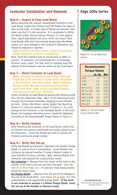
Contactor Installation and Removal<strong>Edge</strong> 400a <strong>Series</strong>Step 6— Inspect & Clean Load BoardBefore mounting the cleaned, reassembled Contactor to theLoad Board, inspect the Contact Land Pad Pattern for signs ofwear on the Gold. If visible signs of Nickel are showing, thenmake sure that it is not excessive. It is acceptable to utilizethe Nickel surface during testing; however, in some applications,signal degradation will occur which can impact Yield.Load Boards with wear that extends deeper than the Nickelsurface can cause damage to the Contacts & Elastomers andshould be replaced or repaired.NOTE: Excessive Load Board wear is caused by excessiveContact deflection or force on the Housing.Next, check the interface area to ensure that no debris ispresent. If necessary, use Compressed Air—or IsopropylAlcohol—and a clean, lint-free cloth to carefully wipe thebottom of the Contactor and the surface of the Load Board.Step 7— Mount Contactor to Load BoardNOTE: <strong>Johnstech</strong> recommends performing a thoroughinspection of the Load Board before initial installationof the Contactor. See Step 6 above. Before inspection,however, verify that your Load Board and Contactormatch each other. Refer to the Load Board Drawingthat was sent to with your Contactor.Fasten Contactor to Load Board by placing the Housing <strong>Guide</strong>Pins into the alignment holes. Next, fit the Mounting Screwsthrough the Contactor Assembly, engaging several threadsby hand. Using a Nut Driver, evenly tighten the MountingScrews in a crisscross pattern shown in Figure 3. To avoiddamage to the Contactor or the threaded inserts in the LoadBoard, the Contactor Mounting Screws should be tightened,according to the Recommended Torque Values in Figure 4.7542136Figure 3: Screw tighteningpatternRecommendedTorque Valuesin.-lb. Nm0-80 1.0 0.112-56 2.0 0.234-40 5.0 0.56M1.4 x 0.3 0.4 0.04M1.6 x 0.35 0.6 0.06M2 x 0.40 1.3 0.15M2.5 x 0.45 2.5 0.28M3 x 0.5 4.5 0.51M4 x 0.7 8.0 0.90Figure 4: RecommendedTorque Values Table8Step 8— Verify ContactsAfter Mounting the Contactor to the Load Board, verify thatall Contacts are properly positioned and evenly spaced acrossthe Elastomers. Insert the Module by hand to actuate theContacts and ensure proper motion.Step 9— Verify Test Set-upVerify the Module-to-Contactor alignment and Handler PlungeDepth, as well as the X-Y presentation. Insert Module intoContactor by manual insertion if using a Manual Loader orauto insertion if using a Handler. Next, remove Module fromContactor and measure the scrub/witness marks:For Centering — Measure from the center of the mark to theoutside of the Pad to the left and then the right. (See Figures24 & 25 on Page 16.) If centered, these measurementsshould be nearly equal.For Plunge Depth — Measure from the end of the Module tothe end of the Scrub Mark. (See Figure 26 on Page 16.) Thismeasurement is the appoximate plunge depth. If the markis not centered or exceeds a 1.60mm Plunge Depth, checkthe set-up of the Handler or Manual Loader.11www.johnstech.com©2009 <strong>Johnstech</strong> International CorporationAll rights reserved.