Maintenance & Inspection Guide Edge 400A Series - Johnstech
Maintenance & Inspection Guide Edge 400A Series - Johnstech
Maintenance & Inspection Guide Edge 400A Series - Johnstech
- No tags were found...

You also want an ePaper? Increase the reach of your titles
YUMPU automatically turns print PDFs into web optimized ePapers that Google loves.
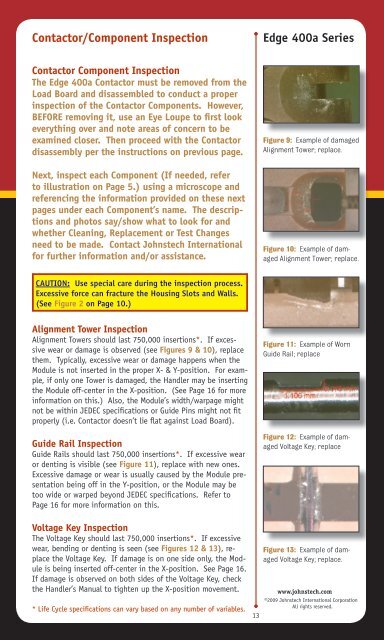
Contactor/Component <strong>Inspection</strong><strong>Edge</strong> 400a <strong>Series</strong>Contactor Component <strong>Inspection</strong>The <strong>Edge</strong> 400a Contactor must be removed from theLoad Board and disassembled to conduct a properinspection of the Contactor Components. However,BEFORE removing it, use an Eye Loupe to first lookeverything over and note areas of concern to beexamined closer. Then proceed with the Contactordisassembly per the instructions on previous page.Next, inspect each Component (If needed, referto illustration on Page 5.) using a microscope andreferencing the information provided on these nextpages under each Component’s name. The descriptionsand photos say/show what to look for andwhether Cleaning, Replacement or Test Changesneed to be made. Contact <strong>Johnstech</strong> Internationalfor further information and/or assistance.Figure 9: Example of damagedAlignment Tower; replace.Figure 10: Example of damagedAlignment Tower; replace.CAUTION: Use special care during the inspection process.Excessive force can fracture the Housing Slots and Walls.(See Figure 2 on Page 10.)Alignment Tower <strong>Inspection</strong>Alignment Towers should last 750,000 insertions*. If excessivewear or damage is observed (see Figures 9 & 10), replacethem. Typically, excessive wear or damage happens when theModule is not inserted in the proper X- & Y-position. For example,if only one Tower is damaged, the Handler may be insertingthe Module off-center in the X-position. (See Page 16 for moreinformation on this.) Also, the Module’s width/warpage mightnot be within JEDEC specifications or <strong>Guide</strong> Pins might not fitproperly (i.e. Contactor doesn’t lie flat against Load Board).<strong>Guide</strong> Rail <strong>Inspection</strong><strong>Guide</strong> Rails should last 750,000 insertions*. If excessive wearor denting is visible (see Figure 11), replace with new ones.Excessive damage or wear is usually caused by the Module presentationbeing off in the Y-position, or the Module may betoo wide or warped beyond JEDEC specifications. Refer toPage 16 for more information on this.Figure 11: Example of Worn<strong>Guide</strong> Rail; replaceFigure 12: Example of damagedVoltage Key; replaceVoltage Key <strong>Inspection</strong>The Voltage Key should last 750,000 insertions*. If excessivewear, bending or denting is seen (see Figures 12 & 13), replacethe Voltage Key. If damage is on one side only, the Moduleis being inserted off-center in the X-position. See Page 16.If damage is observed on both sides of the Voltage Key, checkthe Handler’s Manual to tighten up the X-position movement.* Life Cycle specifications can vary based on any number of variables.13Figure 13: Example of damagedVoltage Key; replace.www.johnstech.com©2009 <strong>Johnstech</strong> International CorporationAll rights reserved.