Maintenance & Inspection Guide Edge 400A Series - Johnstech
Maintenance & Inspection Guide Edge 400A Series - Johnstech
Maintenance & Inspection Guide Edge 400A Series - Johnstech
- No tags were found...

You also want an ePaper? Increase the reach of your titles
YUMPU automatically turns print PDFs into web optimized ePapers that Google loves.
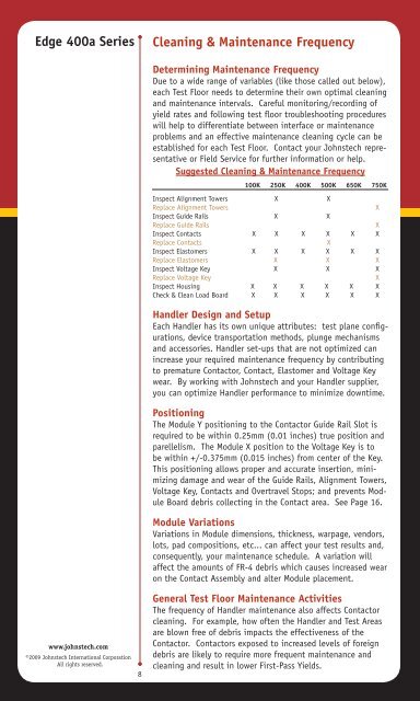
<strong>Edge</strong> 400a <strong>Series</strong>Cleaning & <strong>Maintenance</strong> Frequencywww.johnstech.com©2009 <strong>Johnstech</strong> International CorporationAll rights reserved.8Determining <strong>Maintenance</strong> FrequencyDue to a wide range of variables (like those called out below),each Test Floor needs to determine their own optimal cleaningand maintenance intervals. Careful monitoring/recording ofyield rates and following test floor troubleshooting procedureswill help to differentiate between interface or maintenanceproblems and an effective maintenance cleaning cycle can beestablished for each Test Floor. Contact your <strong>Johnstech</strong> representativeor Field Service for further information or help.Suggested Cleaning & <strong>Maintenance</strong> Frequency100K 250K 400K 500K 650K 750KInspect Alignment Towers X XReplace Alignment TowersXInspect <strong>Guide</strong> Rails X XReplace <strong>Guide</strong> RailsXInspect Contacts X X X X X XReplace ContactsXInspect Elastomers X X X X X XReplace Elastomers X X XInspect Voltage Key X X XReplace Voltage KeyXInspect Housing X X X X X XCheck & Clean Load Board X X X X X XHandler Design and SetupEach Handler has its own unique attributes: test plane configurations,device transportation methods, plunge mechanismsand accessories. Handler set-ups that are not optimized canincrease your required maintenance frequency by contributingto premature Contactor, Contact, Elastomer and Voltage Keywear. By working with <strong>Johnstech</strong> and your Handler supplier,you can optimize Handler performance to minimize downtime.PositioningThe Module Y positioning to the Contactor <strong>Guide</strong> Rail Slot isrequired to be within 0.25mm (0.01 inches) true position andparellelism. The Module X position to the Voltage Key is tobe within +/-0.375mm (0.015 inches) from center of the Key.This positioning allows proper and accurate insertion, minimizingdamage and wear of the <strong>Guide</strong> Rails, Alignment Towers,Voltage Key, Contacts and Overtravel Stops; and prevents ModuleBoard debris collecting in the Contact area. See Page 16.Module VariationsVariations in Module dimensions, thickness, warpage, vendors,lots, pad compositions, etc... can affect your test results and,consequently, your maintenance schedule. A variation willaffect the amounts of FR-4 debris which causes increased wearon the Contact Assembly and alter Module placement.General Test Floor <strong>Maintenance</strong> ActivitiesThe frequency of Handler maintenance also affects Contactorcleaning. For example, how often the Handler and Test Areasare blown free of debris impacts the effectiveness of theContactor. Contactors exposed to increased levels of foreigndebris are likely to require more frequent maintenance andcleaning and result in lower First-Pass Yields.