Maintenance & Inspection Guide Edge 400A Series - Johnstech
Maintenance & Inspection Guide Edge 400A Series - Johnstech
Maintenance & Inspection Guide Edge 400A Series - Johnstech
- No tags were found...

You also want an ePaper? Increase the reach of your titles
YUMPU automatically turns print PDFs into web optimized ePapers that Google loves.
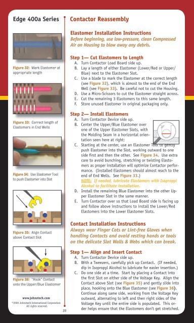
<strong>Edge</strong> 400a <strong>Series</strong>Contactor ReassemblyElastomer Installation InstructionsBefore beginning, use low-pressure, clean CompressedAir on Housing to blow away any debris.Figure 32: Mark Elastomer atappropriate lengthFigure 33: Correct length ofElastomers in End WellsFigure 34: Use Elastomer Toolto push Elastomer into SlotFigure 35: Align Contactabove Contact SlotFigure 36: “Hook” Contactonto the Upper/Blue Elastomerwww.johnstech.com©2009 <strong>Johnstech</strong> International CorporationAll rights reserved.20Step 1— Cut Elastomers to LengthA. Turn Contactor Load Board side up.B. Lay a length of either Elastomer (Lower/Red or Upper/Blue) next to the Elastomer Slot.C. Use a blade to mark the Elastomer at the correct length(see Figure 32), which is almost to the end of the EndWell (see Figure 33). Be careful not to cut the Housing.D. Use a Micro-Scissors to cut the Elastomer straight across.E. Cut the remaining 3 Elastomers to this same length.F. Store unused Elastomer in original packaging only.Step 2— Install ElastomersA. Turn Contactor Device side up.B. Center the Upper/Blue Elastomer overone of the Upper Elastomer Slots, withthe Molding Seam in a horizontal orientationseen here at right:C. Starting at the center, use an Elastomer Tool to gentlypush Elastomer into the Slot, working outward to oneside first and then the other. See Figure 34. Use extracare to avoid bunching, stretching or twisting Elastomersas proper installation will optimize Contactor performance.(Installed Elastomers should almost reach to theend of End Wells. See Figure 33.)NOTE: If needed, lubricate Elastomers with IsopropylAlcohol to facilitate installation.D. Install the remaining Blue Elastomer into the other UpperElastomer Slot in the same manner.E. Turn Contactor over so that Load Board side is facing upand follow above instructions to install the Lower/RedElastomers into the Lower Elastomer Slots.Contact Installation InstructionsAlways wear Finger Cots or Lint-free Gloves whenhandling Contacts and avoid resting hands or toolson the delicate Slot Walls & Webs which can break.Step 1— Align and Insert ContactA. Turn Contactor Device side up.B. With a Tweezers, carefully pick up Contact. (If needed,dip in Isopropyl Alcohol to lubricate for easier insertion.)C. Do one side at a time. Start by placing a Contact intothe first Slot on either side of the Voltage Key. Align theContact above Slot (see Figure 35) and gently slide intoplace, hooking onto the Blue Elastomer (see Figure 36).Continue along same side, working from the Voltage Keyoutward, alternating to left and then right sides of theVoltage Key until the entire side is populated. This orderhelps ensure that the Elastomers don’t get stretched.