Maintenance & Inspection Guide Edge 400A Series - Johnstech
Maintenance & Inspection Guide Edge 400A Series - Johnstech
Maintenance & Inspection Guide Edge 400A Series - Johnstech
- No tags were found...

Create successful ePaper yourself
Turn your PDF publications into a flip-book with our unique Google optimized e-Paper software.
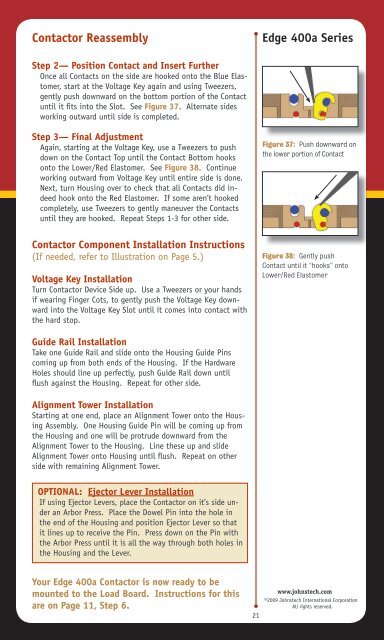
Contactor Reassembly<strong>Edge</strong> 400a <strong>Series</strong>Step 2— Position Contact and Insert FurtherOnce all Contacts on the side are hooked onto the Blue Elastomer,start at the Voltage Key again and using Tweezers,gently push downward on the bottom portion of the Contactuntil it fits into the Slot. See Figure 37. Alternate sidesworking outward until side is completed.Step 3— Final AdjustmentAgain, starting at the Voltage Key, use a Tweezers to pushdown on the Contact Top until the Contact Bottom hooksonto the Lower/Red Elastomer. See Figure 38. Continueworking outward from Voltage Key until entire side is done.Next, turn Housing over to check that all Contacts did indeedhook onto the Red Elastomer. If some aren’t hookedcompletely, use Tweezers to gently maneuver the Contactsuntil they are hooked. Repeat Steps 1-3 for other side.Figure 37: Push downward onthe lower portion of ContactContactor Component Installation Instructions(If needed, refer to Illustration on Page 5.)Voltage Key InstallationTurn Contactor Device Side up. Use a Tweezers or your handsif wearing Finger Cots, to gently push the Voltage Key downwardinto the Voltage Key Slot until it comes into contact withthe hard stop.Figure 38: Gently pushContact until it “hooks” ontoLower/Red Elastomer<strong>Guide</strong> Rail InstallationTake one <strong>Guide</strong> Rail and slide onto the Housing <strong>Guide</strong> Pinscoming up from both ends of the Housing. If the HardwareHoles should line up perfectly, push <strong>Guide</strong> Rail down untilflush against the Housing. Repeat for other side.Alignment Tower InstallationStarting at one end, place an Alignment Tower onto the HousingAssembly. One Housing <strong>Guide</strong> Pin will be coming up fromthe Housing and one will be protrude downward from theAlignment Tower to the Housing. Line these up and slideAlignment Tower onto Housing until flush. Repeat on otherside with remaining Alignment Tower.OPTIONAL: Ejector Lever InstallationIf using Ejector Levers, place the Contactor on it’s side underan Arbor Press. Place the Dowel Pin into the hole inthe end of the Housing and position Ejector Lever so thatit lines up to receive the Pin. Press down on the Pin withthe Arbor Press until it is all the way through both holes inthe Housing and the Lever.Your <strong>Edge</strong> 400a Contactor is now ready to bemounted to the Load Board. Instructions for thisare on Page 11, Step 6.21www.johnstech.com©2009 <strong>Johnstech</strong> International CorporationAll rights reserved.