hbrisc2 - Microelectronics
hbrisc2 - Microelectronics
hbrisc2 - Microelectronics

Create successful ePaper yourself
Turn your PDF publications into a flip-book with our unique Google optimized e-Paper software.
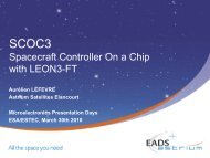
GSTP2-IMCMESTEC/Contract N° 13492/99/NL/PAFinal PresentationDecember 2004TN0342-Iss10.pptAll right reserved: Disclosure to third parties of this document or any part thereof, or the use of any information contained therein for purposes other than provided for by this document, is not permitted exceptwith prior and express written permission of S.A.B.C.A.06/12/20041
IMCM Project Assessment BRISC architecture Targeted applications Architecture overview IMCM ASIC HBRISC2 development logic HBRISC2 validation strategy HBRISC2 application development process Production& validation tools Synthesizer Macro Library Assembler Unit test tool Validation of the macros and Simulink library Win-Seracq tool IMCM demonstration application HBRISC2 perspectives Current and coming applications Towards HBRISC2 Application+ Tool IMCM conclusionTN0342-Iss10.pptAll right reserved: Disclosure to third parties of this document or any part thereof, or the use of any information contained therein for purposes other than provided for by this document, is not permitted exceptwith prior and express written permission of S.A.B.C.A.06/12/20042
BRISC Architecture Overview Targeted to the command of high performance electrical motors in criticalapplications True from the very first release of BRISC & continuously improved Application key requirements Versatile, standard product Hard real-time, with tight HW-SW synchronization Fully predictable execution time No corner-case caused by the use of digital domain High visibility on the internal functioning Architecture impact Data path optimized for vector control, motor modeling... Intrinsic high computing power: floating multiplication, division (HBRISC2) Saturating arithmetic (no exceptions) RISC machine High digital function integration (avoid glue logic, on-board µP or FPGA...) High Speed serial link dedicated to reporting Straightforward compatibility to standard components (ADC, RAM, Flash, EEPROM,...)TN0342-Iss10.pptAll right reserved: Disclosure to third parties of this document or any part thereof, or the use of any information contained therein for purposes other than provided for by this document, is not permitted exceptwith prior and express written permission of S.A.B.C.A.06/12/20043
BRISC Architecture Overview (H)BRISC2 is specifically targeted to Hi-Rel applications Space environment Radiation effects (neutrons, heaving ions...) Automatic SEU correction with : minimal interruption and user-transparent execution No impact on board frequency Temperature: -55°C to 125°C Technology reliability Aeronautics/Military environment Domain is more and more sensitive to SEU effects Temperature: -55°C to 125°C Technology reliabilityTN0342-Iss10.pptAll right reserved: Disclosure to third parties of this document or any part thereof, or the use of any information contained therein for purposes other than provided for by this document, is not permitted exceptwith prior and express written permission of S.A.B.C.A.06/12/20044
BRISC Architecture Overview Provide main peripheral functions required in loop systems (onlyHBRISC2): Includes: Communication with sensors feed-back (ADC) PWM generation Communication with outer peripherals (on-board computer, debugging environment,...) Automatic live at-power up ... Autonomous functions to minimize CPU load impact Programmable in SW Flexible with standard componentsTN0342-Iss10.pptAll right reserved: Disclosure to third parties of this document or any part thereof, or the use of any information contained therein for purposes other than provided for by this document, is not permitted exceptwith prior and express written permission of S.A.B.C.A.06/12/20045
BRISC Architecture OverviewH B RISC 2: Latest release of BRISC architecture2: 2nd release/evolution; post BRISC/BRISC11Reduced Instruction Set Computer: One instruction per cycleBi: Embedded Dual floating-point units (A/B)Hardened: faces radiation effectsTN0342-Iss10.pptAll right reserved: Disclosure to third parties of this document or any part thereof, or the use of any information contained therein for purposes other than provided for by this document, is not permitted exceptwith prior and express written permission of S.A.B.C.A.06/12/20046
BRISC Architecture OverviewProgrambusINSTRUCTION REGISTER 32+7HBRISC2CORE 16ADDRESSREGISTERAddressbusON-CHIP SEUERRORDETECTION/CORRECTIONUNITON-CHIP MEMORYSEU ERRORCORRECTIONUNITINSTRUCTIONSEQUENCERHBRISC2Unit AGLOBALREGISTERSREGISTERBANKFLOATINGPOINTUNITINSTRUCTIONDECODERUnit BGLOBALREGISTERSREGISTERBANKFLOATINGPOINTUNITGLOBALREGISTERSFIXED POINTARITHMETICUNITRIOUnit SURPADBOOTROMREGISTERSSEUDETECTION/CORRECTIONUNIT46/ADCinterfaceI/OinterfaceON-CHIP PERIPHERALINTERFACEPeripheralbusProg.outputsSerial port(SPI)4/3//1CRCcheckmotorPWMexcitationPWMSerialFast linksoftwaretimerTN0342-Iss10.pptHBRISC2PERIPHERAL 18All right reserved: Disclosure to third parties of this document or any part thereof, or the use of any information contained therein for purposes other than provided for by this document, is not permitted exceptwith prior and express written permission of S.A.B.C.A. 6 2 206/12/20047
BRISC Architecture Overview RISC architecture Deterministic code execution time Allows easy code optimization Instruction decoding and sequencing issimple Low circuit areaProgrambusINSTRUCTION REGISTERON-CHIP SEUERRORDETECTION/CORRECTIONUNIT 32+7ON-CHIP MEMORYSEU ERRORCORRECTIONUNITHBRISC2CORE 16ADDRESSREGISTERINSTRUCTIONSEQUENCERAddressbus Data definition: high precision andmagnitude 16 bits mantissa, 2’s complement 8 bits exponent, 2’s complement Dual floating point unit Vectorial data-path with SIMD architecture Exploits intrinsic parallelism of targetedapplicationsUnit AGLOBALREGISTERSREGISTERBANKFLOATINGPOINTUNITINSTRUCTIONDECODERUnit BGLOBALREGISTERSREGISTERBANKFLOATINGPOINTUNITGLOBALREGISTERSFIXED POINTARITHMETICUNITRIOUnit SURPADBOOTROMREGISTERSSEUDETECTION/CORRECTIONUNITTN0342-Iss10.pptAll right reserved: Disclosure to third parties of this document or any part thereof, or the use of any information contained therein for purposes other than provided for by this document, is not permitted exceptwith prior and express written permission of S.A.B.C.A.06/12/20048
BRISC Architecture Overview On-chip data memory: organized in 16 banksof 8 registers each Avoid use of external memory to storefrequently used data Access time restricted to one instruction cycle(>< several cycles for external memory)ProgrambusINSTRUCTION REGISTERON-CHIP SEUERRORDETECTION/CORRECTIONUNIT 32+7ON-CHIP MEMORYSEU ERRORCORRECTIONUNITHBRISC2CORE 16ADDRESSREGISTERINSTRUCTIONSEQUENCERAddressbus SU unit: Special Unit dedicated to addresscomputing 16-bit integer Dedicated communication registers: RIO&RPAD Arithmetic Saturating Exception-freeUnit AGLOBALREGISTERSREGISTERBANKFLOATINGPOINTUNITINSTRUCTIONDECODERUnit BGLOBALREGISTERSREGISTERBANKFLOATINGPOINTUNITGLOBALREGISTERSFIXED POINTARITHMETICUNITRIOUnit SURPADBOOTROMREGISTERSSEUDETECTION/CORRECTIONUNITTN0342-Iss10.pptAll right reserved: Disclosure to third parties of this document or any part thereof, or the use of any information contained therein for purposes other than provided for by this document, is not permitted exceptwith prior and express written permission of S.A.B.C.A.06/12/20049
BRISC Architecture Overview: Peripheral Unit46/ADCinterfaceI/OinterfaceON-CHIP PERIPHERALINTERFACEPeripheralbusProg.outputsSerial port(SPI)4/3//1CRCcheckmotorPWMexcitationPWMSerialFast linksoftwaretimerHBRISC2PERIPHERAL 3 independent three-phase each (sixtransistors), PWM generators Autonomous, fully programmable,dead time software control 6 channels for sensors excitation Complementary outputs,programmable dead time SPI Communication with intelligentexternal peripherals High Speed serial link for data reporting andsystem-level debugging 18 6 2 2 General-purpose parallel I/O port Programmable, designed for slow peripheralssuch as EEPROM or Flash memories Software timer Synchronization between software andhardware Programmable ADC interface Configurable for any ADC, up to 8 samples persoftware cycle CRC computation unit Checksum of uploaded code, from I/O or SPI 4 general-purpose programmable outputsTN0342-Iss10.pptAll right reserved: Disclosure to third parties of this document or any part thereof, or the use of any information contained therein for purposes other than provided for by this document, is not permitted exceptwith prior and express written permission of S.A.B.C.A.06/12/200410
BRISC Architecture Overview: Radiation Effects LATCH-UP Parasitic shortcut between VDD and GND Caused by heavy ions→ HBRISC technology (ATMEL MH1RT) guarantees Latch-Up threshold to 80MeV/g/cm2 TID (Total Ionizing Dose) Undesired chip consumption increase starting from a threshold (in RAD) Caused by heavy energy particles→ HBRISC technology (ATMEL MH1RT) guarantees 200 KRAD (Si) radiation levelTN0342-Iss10.pptAll right reserved: Disclosure to third parties of this document or any part thereof, or the use of any information contained therein for purposes other than provided for by this document, is not permitted exceptwith prior and express written permission of S.A.B.C.A.06/12/200411
BRISC Architecture Overview: Radiation Effects SEU (Single Event Upset) Bit flipping on storage cells (register, memory cell…) Caused by heavy ions radiations Critical components in typical HBRISC board: CPU registers, SRAM,Flash/EEPROMLow voltage power busSRAM(APPLICATION)programbusCPUHBrisc2Power drivecommandSensorexcitation(E)EPROM(BACK-UP)I/ObusADC cntrlSensors signalsADCTN0342-Iss10.pptAll right reserved: Disclosure to third parties of this document or any part thereof, or the use of any information contained therein for purposes other than provided for by this document, is not permitted exceptwith prior and express written permission of S.A.B.C.A.06/12/200412
BRISC Architecture Overview: Radiation Effects BRISC SEU-hardened architecture: instruction/data SRAM protectionProgrambus46/INSTRUCTION REGISTERON-CHIP SEUERRORDETECTION/CORRECTIONUNITUnit AGLOBALREGISTERSREGISTERBANKFLOATINGPOINTUNITADCinterfaceI/OinterfaceINSTRUCTIONDECODERGLOBALREGISTERSREGISTERBANKFLOATINGPOINTUNITCRCcheck 32+8Unit BON-CHIP MEMORYSEU ERRORCORRECTIONUNITGLOBALREGISTERSFIXED POINTARITHMETICUNITRIOUnit SURPADON-CHIP PERIPHERALINTERFACEmotorPWMHBRISC2COREPeripheralbusexcitationPWMSerialFast link 16ADDRESSREGISTERINSTRUCTIONSEQUENCERBOOTROMREGISTERSSEUDETECTION/CORRECTIONUNITSerial port(SPI)softwaretimerAddressbus4/• “LIVE” CORRECTION BEFOREINSTRUCTION DECODING• AUTOMATIC SRAM CORRECTIONON HBRISC2 STOLEN CYCLES• MODIFIED HAMMING CODE detects and corrects all 1-bit errors detects all 2-bit errors detects part of multiple-bit errors• NO ADDED DELAY DURINGINSTRUCTION FETCH• HARDWARE REPORTINGHBRISC2PERIPHERAL 18 6 2 1TN0342-Iss10.pptAll right reserved: Disclosure to third parties of this document or any part thereof, or the use of any information contained therein for purposes other than provided for by this document, is not permitted exceptwith prior and express written permission of S.A.B.C.A.06/12/200413
BRISC Architecture Overview: Radiation Effects BRISC SEU-hardened architecture: on-chip (bank register) SRAM protectionProgrambusINSTRUCTION REGISTERON-CHIP SEUERRORDETECTION/CORRECTIONUNITUnit AGLOBALREGISTERSREGISTERBANKFLOATINGPOINTUNIT 32+8INSTRUCTIONDECODERUnit BGLOBALREGISTERSREGISTERBANKFLOATINGPOINTUNITON-CHIP MEMORYSEU ERRORCORRECTIONUNITGLOBALREGISTERSFIXED POINTARITHMETICUNITRIOHBRISC2COREUnit SURPAD 16ADDRESSREGISTERINSTRUCTIONSEQUENCERBOOTROMREGISTERSSEUDETECTION/CORRECTIONUNITAddressbus• DETECTION/CORRECTION MADEDURING INSTRUCTION EXECUTION• ON ERROR, RE-EXECUTIONFOLLOWS CORRECTION• MODIFIED HAMMING CODE AS PEREXTERNAL SRAM• HARDWARE REPORTING46/ADCinterfaceI/OinterfaceON-CHIP PERIPHERALINTERFACEPeripheralbusSerial port(SPI)4/CRCcheckmotorPWMexcitationPWMSerialFast linksoftwaretimerHBRISC2PERIPHERAL 18 6 2 1TN0342-Iss10.pptAll right reserved: Disclosure to third parties of this document or any part thereof, or the use of any information contained therein for purposes other than provided for by this document, is not permitted exceptwith prior and express written permission of S.A.B.C.A.06/12/200414
BRISC Architecture Overview: Radiation Effects BRISC SEU-hardened architecture: on-chip registers protectionProgrambusINSTRUCTION REGISTERON-CHIP SEUERRORDETECTION/CORRECTIONUNITUnit AGLOBALREGISTERSREGISTERBANKFLOATINGPOINTUNIT 32+7INSTRUCTIONDECODERUnit BGLOBALREGISTERSREGISTERBANKFLOATINGPOINTUNITON-CHIP MEMORYSEU ERRORCORRECTIONUNITGLOBALREGISTERSFIXED POINTARITHMETICUNITRIOHBRISC2COREUnit SURPAD 16ADDRESSREGISTERINSTRUCTIONSEQUENCERBOOTROMREGISTERSSEUDETECTION/CORRECTIONUNITAddressbus• USE OF “HARDENED-SEU”REGISTERS AND LATCHES• AVAILABLE IN ATMEL MH1RTSTANDARD LIBRARY• ALL REGISTERS/LATCHES HAVEBEEN HARDENED EXCEPT/•BANK REGISTERS (TOO AREACONSUMING•JTAG BOUNDARY_SCAN CHAIN(UNUSED ON FLIGHT)46/ADCinterfaceI/OinterfaceON-CHIP PERIPHERALINTERFACEPeripheralbusProg.outputsSerial port(SPI)4/3//1CRCcheckmotorPWMexcitationPWMSerialFast linksoftwaretimerTN0342-Iss10.pptHBRISC2PERIPHERAL 18 6 2 2All right reserved: Disclosure to third parties of this document or any part thereof, or the use of any information contained therein for purposes other than provided for by this document, is not permitted exceptwith prior and express written permission of S.A.B.C.A.06/12/200415
BRISC Architecture Overview: Radiation Effects BRISCProgramAddressSEU-hardened architecture: boot rom protectionbusINSTRUCTION REGISTERON-CHIP SEUERRORDETECTION/CORRECTIONUNITUnit AGLOBALREGISTERSREGISTERBANKFLOATINGPOINTUNIT 32+7INSTRUCTIONDECODERUnit BGLOBALREGISTERSREGISTERBANKFLOATINGPOINTUNITON-CHIP MEMORYSEU ERRORCORRECTIONUNITGLOBALREGISTERSFIXED POINTARITHMETICUNITRIOHBRISC2COREUnit SURPAD 16ADDRESSREGISTERINSTRUCTIONSEQUENCERBOOTROMREGISTERSSEUDETECTION/CORRECTIONUNITbus• BASED ON CRC BLOCK• ONLY ERROR DETECTION ISPOSSIBLE (NO CORRECTIONPERFORMED)• HARDWARE AND SOFTWAREREPORTING46/ADCinterfaceI/OinterfaceON-CHIP PERIPHERALINTERFACEPeripheralbusProg.outputsSerial port(SPI)4/3//1CRCcheckmotorPWMexcitationPWMSerialFast linksoftwaretimerTN0342-Iss10.pptHBRISC2PERIPHERAL 18 6 2 2All right reserved: Disclosure to third parties of this document or any part thereof, or the use of any information contained therein for purposes other than provided for by this document, is not permitted exceptwith prior and express written permission of S.A.B.C.A.06/12/200416
Brisc Architecture Overview: ASIC Technology ATMEL MH1RT Rad-Tolerant Latch-up immune (> 80 Mev/g/cm2) SEU hardened registers Gate-array 0.35 µm 5V I/O pads 3.3 V Core HBRISC2 Matrix: MH1_156E Package: MQFP-256 4 on-chip dual-port RAM Bank register SPI interface buffersTN0342-Iss10.pptAll right reserved: Disclosure to third parties of this document or any part thereof, or the use of any information contained therein for purposes other than provided for by this document, is not permitted exceptwith prior and express written permission of S.A.B.C.A.06/12/200417
IMCM ASIC -HBRISC2- development logic Final product is an ASIC (Application SpecificIntegrated Circuit) Simuations runs are time-consuming: extensivetesting is difficult to achieve Major design error must be avoided: ASIC iterationsare long and expensive HBRISC2 architecture is complex to test: thoroughtesting is mandatory… Solution: Test Platform with FPGA prototyping Early debugging of HBRISC2 VHDL sources Thorough tests can be made on breadboard A physical implementation is available: SW team canstart developing macros and application Design-to-silicon cycle is short (typically a fewhours) Note: “At-speed” tests(60 MHz) are not feasibleASICVHDLDESIGNVALIDATEDASICP&RHBRISC2VHDLERROROKFPGAVHDLFPGAPROTOTESTTN0342-Iss10.pptAll right reserved: Disclosure to third parties of this document or any part thereof, or the use of any information contained therein for purposes other than provided for by this document, is not permitted exceptwith prior and express written permission of S.A.B.C.A.06/12/200418
IMCM ASIC -HBRISC2- development logic VHDL-based design Schematic-based designs are nowadays obsolete Portable design (suits FPGA prototyping methodology) Differences between ASIC VHDL and FPGA VHDL: Embedded on-chip memories Programmable outputs Increase readability Currently supported and encourages by all founders Use of industry well-known CAD tools: Synopsys, Cadence… Efficiency is world-wide recognized Already owned by SABCA for past and current designs Scan/JTAG insertion and ATPG is made by Atmel Layout made by AtmelTN0342-Iss10.pptAll right reserved: Disclosure to third parties of this document or any part thereof, or the use of any information contained therein for purposes other than provided for by this document, is not permitted exceptwith prior and express written permission of S.A.B.C.A.06/12/200419
IMCM ASIC -HBRISC2- development logic Implementation: Selected FPGA is Actel ProASIC A500K On-board reprogrammable SABCA already works with Actel Design partitioned in two FPGAs: Core UnitA500K270 Peripheral unitA500K180TN0342-Iss10.pptAll right reserved: Disclosure to third parties of this document or any part thereof, or the use of any information contained therein for purposes other than provided for by this document, is not permitted exceptwith prior and express written permission of S.A.B.C.A.06/12/200420
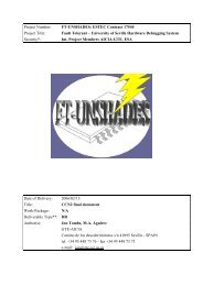
NOT USEDNOT USEDBXADD(0)BXADD(1)BXADD(2)D_CBARVSSVCSPIBOOT_MSTRMAIN_CKPROGOUT(0)ADC_MUXSELECT(0)ADC_MUXSELECT(1)VSSVCBXADD(3)BXADD(4)BXADD(5)PROGOUT(1)PROGOUT(2)PROGOUT(3)R_WBADC_MUXSELECT(2)VSSVCBXADD(6)BXADD(7)BXADD(8)SERIAL_CLKSERI AL_DATAADC_MUXSELECT(3)VSSVCBXADD(9)BXADD( 10)BXADD( 1)SI OP_CSBAR(0)SI OP_CSBAR(1)SI OP_OEBAR(0)VSSVDBXADD( 12)BXADD( 13)BXADD( 14)SI OP_CSBAR(2)SI OP_CSBAR(3)SI OP_OEBAR(1)VSSVCBXADD( 15)NOT USEDSI OP_OEBAR(2)SI OP_OEBAR(3)ADCIOBUS(0)ADCIOBUS(1)ADCIOBUS(2)VSSVCSIOP_WE BAR(0)SIOP_WE BAR(1)VSSVCNOT USEDNOT USED12345678910111213141516171819202122232425262728293031323334353637383940414243444546474849505152535455565758596061626364NOT USEDNOT USED25 625 5N O T US E D 656VCCVSSSEL_BOOTASVCCVSSRESET_BARDSBXI O(0)BXI O(1)BXI O(2)BXI O(3)BXI O(4)BXI O(5)VCCVSSBXI O(6)BXI O(7)BXI O(8)BXI O(9)BXI O(10)BXI O(11)BXI O(12)VCCVSSBXI O(13)BXI O(14)BXI O(15)BXI O(16)BXI O(17)BXI O(18)BXI O(19)VCCVSSBXI O(20)BXI O(21)BXI O(22)BXI O(23)BXI O(24)BXI O(25)BXI O(26)VCCVSSBXI O(27)BXI O(28)BXI O(29)BXI O(30)BXI O(31)BXI O(32)BXI O(33)VCCVSSBXI O(34)BXI O(35)VCCVSSBXI O(36)BXI O(37)BXI O(38)NOT USEDNOT USEDNOT USED25 425 325 225 125024924824724624524424324224124023923823723623523423323223123029282726252423222120219218217216215214213212211210209208207206205204203202201200199198197196195194193N O T US E DS IO P _ W E B A R (2 ) 67S IO P _ W E B A R (3 )6869707172737475767A D CI O B U S (3 )A D CI O B U S (4 )VS SV C CA D CI O B U S (5 )A D CI O B U S (6 )A D CI O B U S (7 )A D CI O B U S (8 )VS SV C CA D CI O B U S (9 )A D C IO B U S (1 0 )78798081828384858687889909192939495969798910 010 110 210 310 410 510 610 710 810 91 01 11 21 31 41 51 61 71 81 912 012 112 212 312 412 512 612 712 8A D C IO B U S (1 1 )A D C IO B U S (1 2 )A D C IO B U S (1 3 )A D C IO B U S (1 4 )A D C IO B U S (1 5 )VS SV C CA DC _ E O C B A R (0 )A DC _ E O C B A R (1 )A DC _ E O C B A R (2 )A DC _ E O C B A R (3 )T D IT D OT C KT M ST RS TN O T US E DN O T US E DS IO P _ A D D (0 )S IO P _ A D D (1 )S IO P _ A D D (2 )S IO P _ A D D (3 )S IO P _ A D D (4 )S IO P _ A D D (5 )S IO P _ A D D (6 )S IO P _ A D D (7 )S IO P _ A D D (8 )S IO P _ A D D (9 )S IO P _ A D D (1 0 )S IO P _ A D D (1 1 )S IO P _ A D D (1 2 )VS SV C CS IO P _ A D D (1 3 )S IO P _ A D D (1 4 )S IO P _ A D D (1 5 )S IO P _ A D D (1 6 )S IO P _ A D D (1 7 )S O FT _ T ICS O F T _T IC _ D E L AY E DVS SV C CS Y N CH R _ T ICT ES TT E S T _C L KT E S T _S EN O T US E DN O T US E D192191190189188187186185184183182181180179178177176175174173172171170169168167166165164163162161160159158157156155154153152151150149148147146145144143142141140139138137136135134133132131130129NOT USEDNOT USEDNOT USEDINT_BARNOT USEDNOT USEDVCCVSSNOT USEDNOT USEDSE3_BSE3_ASE2_BSE2_AVCCVSSSE1_BSE1_ASEU_ERRORSEU_CORR_ISEU_CORR_EM3_PWM3HM3_PWM3LM3_PWM2HM3_PWM2LM3_PWM1HM3_PWM1LNOT USEDNOT USEDM2_PWM3HM2_PWM3LM2_PWM2HM2_PWM2LM2_PWM1HM2_PWM1LVCCVSSUPLOAD_ERUPLOAD_IPIACKBARCRC_CHECKODD_CKM1_PWM3HM1_PWM3LM1_PWM2HM1_PWM2LM1_PWM1HM1_PWM1LSPI _OUTSPI _CSBARSPI _I NSPI _CLKADC_CS(3)ADC_CS(2)ADC_CS(1)ADC_CS(0)VCCVSSVCCVSSADC_SOCADC_R_CNOT USEDNOT USEDIMCM ASIC -HBRISC2- development logic Design FlowVHDLDesigntestbenchRTLsimulationCADENCE NC-VHDLFPGALogicsynthesisconstraintspre-layouttiming fileASICLogicsynthesisnetlistsimulationSYNOPSYSDESIGN COMPILER (ASIC)FPGA COMPILER 2 (FPGA)Scan/JTAGinsertionATMEL TOOLS (ASIC)HBRISC2post-layouttiming fileLayoutpost-layoutsimulationconstraintspost-layouttiming fileLayoutsign-offsimulationATMEL TOOLS (ASIC)ACTEL ASICMASTER (FPGA)To FPGAtest boardstatictiminganalysisTo foundrySYNOPSYSDESIGN TIME (ASIC)TN0342-Iss10.pptAll right reserved: Disclosure to third parties of this document or any part thereof, or the use of any information contained therein for purposes other than provided for by this document, is not permitted exceptwith prior and express written permission of S.A.B.C.A.06/12/200421
Hbrisc2 Circuit Validation Strategy: Items Under Test Purpose: verification versus TNS0015 (“HBRISC2 design and architecturalspecification”). Items under test (described in VP0263 “HBRISC2 validation plan): Functional DC parametersInstruction setPeripherals Units: PWM, HSSL, SPISpecial features: Upload,...AC parametersI/O propagation delaysI/O setup/hold timingsMax frequencyI/O pads voltages levelsI/O pads current levels,ConsumptionEnvironment ...Temperature (-55°C;25°C;125°C)SEU correction mechanismTN0342-Iss10.pptAll right reserved: Disclosure to third parties of this document or any part thereof, or the use of any information contained therein for purposes other than provided for by this document, is not permitted exceptwith prior and express written permission of S.A.B.C.A.06/12/200422
Hbrisc2 Circuit Validation Strategy: Hbrisc2 Models 1st Model: ASIC Final product: PIN number is 5962-01B0106QYCFPK Corresponds to circuit manufactured by ATMEL 2nd Model: VHDL RTL model VHDL description of HBRISC2 design Definition is sufficient to verify functional requirements but not AC parameters DC parameters Environmental requirements except SEUTN0342-Iss10.pptAll right reserved: Disclosure to third parties of this document or any part thereof, or the use of any information contained therein for purposes other than provided for by this document, is not permitted exceptwith prior and express written permission of S.A.B.C.A.06/12/200423
Hbrisc2 Circuit Validation Strategy: Hbrisc2 Models 3rd Model: VHDL gate model Corresponds to netlist (gate-level) of HBRISC2 design Model integrates post-layout timings Definition is sufficient to verify functional requirements but not DC parameters Environmental requirements except SEU 4th Model: FPGA Emulator HBRISC2 Prototype used during for design debugging Only functional requirements can be testedTN0342-Iss10.pptAll right reserved: Disclosure to third parties of this document or any part thereof, or the use of any information contained therein for purposes other than provided for by this document, is not permitted exceptwith prior and express written permission of S.A.B.C.A.06/12/200424
Hbrisc2 Circuit Validation Strategy: Test Means1st test platform: VHDL simulator Allows RTL-level, gate-level (pre & post layout simulations) Suited for small test patterns (simulation is slow especially during gate-level) Easy debugging (full visibility of all internal nodes) 2nd test platform: Atmel tester (Sentry 15) Use of final physical implementation Number of test vectors is limited (Atmel quota) Atmel tester frequency limited to 20 MHz.TN0342-Iss10.pptAll right reserved: Disclosure to third parties of this document or any part thereof, or the use of any information contained therein for purposes other than provided for by this document, is not permitted exceptwith prior and express written permission of S.A.B.C.A.06/12/200425
Hbrisc2 Circuit Validation Strategy: Test Means3rd test platform: HBRISC2 test board Use of final physical implementation “At-speed” test is possible at ambient temperature.4th test platform: FPGA emulator Use of an intermediate implementation of HBRISC2. Interest is limited regarding HBRISC2 validation but permits : Early macros/application development. Efficient VHDL design debugging Re-use of test patterns in the scope of HBRISC2 (ASIC) validationTN0342-Iss10.pptAll right reserved: Disclosure to third parties of this document or any part thereof, or the use of any information contained therein for purposes other than provided for by this document, is not permitted exceptwith prior and express written permission of S.A.B.C.A.06/12/200426
Hbrisc2 Circuit Validation Strategy: Verification MatrixFunctionalVHDLSimulatorLimitedMUT: GATEHBRISC2Test BoardRe-use of tests developedwith FPGA emulator(macros…)MUT: ASICDC parameters NA NAAC parametersEnvironmentAll AC parameters(including max. frequency)MUT: GATESEU testsMUT: GATEMax. frequency @ ambienttemperatureMUT: ASICNAAtmelTesterLimitedMUT: ASICAll DC parametersMUT: ASICAll parameters except max.frequencyMUT: ASICTemperature and supplyvoltageMUT: ASICMUT = Model Under TestTN0342-Iss10.pptAll right reserved: Disclosure to third parties of this document or any part thereof, or the use of any information contained therein for purposes other than provided for by this document, is not permitted exceptwith prior and express written permission of S.A.B.C.A.06/12/200427
Hbrisc2 Circuit Validation Strategy: Test ResultsFunctional Successfully passed on HBRISC2 board and Atmel tester Complete Test Report is in TR0024AC parameters Successfully passed on Atmel tester Successfully passed on GATE modelHBRISC2 board Max frequency on STA: 54 MHz Successfully passed on HBRISC2 board Tests run @ 60 MHz (at ambient temperature) Complete Test Reports is in TR0024 and TN0021TN0342-Iss10.pptAll right reserved: Disclosure to third parties of this document or any part thereof, or the use of any information contained therein for purposes other than provided for by this document, is not permitted exceptwith prior and express written permission of S.A.B.C.A.06/12/200428
Hbrisc2 Circuit Validation Strategy: Test ResultsDC parametersSuccessfully passed on Atmel tester: measurements within specification inAID (TNS0211).Dynamic consumption (Core+I/O): < 0.5 WComplete Test report is in TR0024EnvironmentSuccessfully passed on Atmel tester: measurements within specification inAID (TNS0211).Test report in TR0024SEU test plan in VP262 “SEU validation plan”SEU test report in TR0257 “SEU validation report”TN0342-Iss10.pptAll right reserved: Disclosure to third parties of this document or any part thereof, or the use of any information contained therein for purposes other than provided for by this document, is not permitted exceptwith prior and express written permission of S.A.B.C.A.06/12/200429
Hbrisc2 Circuit Validation Strategy: Hbrisc2 Status PRE-layout frequency: 50 MHz POST-layout frequency: 54 MHz Design area: 260 074 cells ATPG Test coverage: 97.53 % cells sites used: 54.05% IO sites used: 40.29% SEU Flip-flop count: 7039 Non-SEU flip-flops: 597 Latches count: 39 Cells distribution:CORE10% 2%SCAN88%JTAGTN0342-Iss10.pptAll right reserved: Disclosure to third parties of this document or any part thereof, or the use of any information contained therein for purposes other than provided for by this document, is not permitted exceptwith prior and express written permission of S.A.B.C.A.06/12/200430
HBRISC2 application development processSimulink simulationSimulinkmodelLibrary(Simulink & BRISC)SynthesizerAssemblerHighlyoptimisedmodulesTarget H/WSeracqCheckOKAcceptanceTN0342-Iss10.pptAll right reserved: Disclosure to third parties of this document or any part thereof, or the use of any information contained therein for purposes other than provided for by this document, is not permitted exceptwith prior and express written permission of S.A.B.C.A.06/12/200431
Description of the Production and validation tools A certain number of tools have been developed around Brisc processorsin order to allow efficient production of good quality code. The main tools are the following: The synthesiser that takes a Simulink diagram and generates assembly code. The Assembler that produces binary code. The Seracq-Win32 that supports tests on target hardware. It performsuploading of a program, running of command scripts, and acquisition andvisualisation of parameters transmitted through the HSSL. The total_nw program that allows unit tests of the macros to be executed alltogether in a single run. A set of scripts that allows unit tests of the Simulink blocks to be performedautomatically.TN0342-Iss10.pptAll right reserved: Disclosure to third parties of this document or any part thereof, or the use of any information contained therein for purposes other than provided for by this document, is not permitted exceptwith prior and express written permission of S.A.B.C.A.06/12/200432
Production chain of HBRISC2 application SWSIMULINK library(lib_imcm.mdl)Macro definition(macros.lst)Macro library(bh files)TargethardwareSIMULINK modelSimplified(mdl file)SynthesisedSIMULINK model(mdl file)SYNTHESISERCode source(b2c file)CompilationHbrass2.exeBinary code(bin file)Softwarevalidationtesting(Seracq-Win32)Variabledefinition file(m files)HBrisc2 parameterinitialisation(initialisations.bc)TN0342-Iss10.pptAll right reserved: Disclosure to third parties of this document or any part thereof, or the use of any information contained therein for purposes other than provided for by this document, is not permitted exceptwith prior and express written permission of S.A.B.C.A.06/12/200433
The synthesiser and the software libraries (1) The actuator modelling and tuning isperformed with Simulink. First, a high-level model of the wholeactuation system (control loop, motor,load, power electronics) is done. Afterwards, the control loop is re-writtenwith blocks coming exclusively from theHBRISC2 library. Simulations will show that both modelsare equivalent.TN0342-Iss10.pptAll right reserved: Disclosure to third parties of this document or any part thereof, or the use of any information contained therein for purposes other than provided for by this document, is not permitted exceptwith prior and express written permission of S.A.B.C.A.06/12/200434
Validation of the synthesiser The synthesiser is a single executable, but is divided in several modules: A parser that reads the main input files and builds an equivalent objectstructure in memory A sorter that orders the blocks and slots. An assigner that gives units and registers to the macros, so the macros callscan be fulfilled. A generator that produces the final code, and inserts intermediate macrocalls to ensure integrity of the information. Specific test cases have been created to check that each of thesemodules worked correctly. A test case with the same complexity as the application has beensynthesised and its generated code carefully checked. Integration and validation tests have used code generated by thesynthesiser.TN0342-Iss10.pptAll right reserved: Disclosure to third parties of this document or any part thereof, or the use of any information contained therein for purposes other than provided for by this document, is not permitted exceptwith prior and express written permission of S.A.B.C.A.06/12/200436
Macro libraryControllerRegulationVCTCutPowerIfStandby3SC1Dimmer3SC1Limiter2SC1OverflowWithSaturationSC1PositionToSpeed3SCLActuatorPositionVCTActuatorPositionSCLElectricalAngle3SCLElectricalAngleSCLMultiplicationVCTModulusLimiter3VCTNormalizeFundamental2SCLBackwardEulerLowPass3SCLBackwardEulerPI2SCLCorrectAfterRegulator2SCLGainSCLRegulationErrorVCTMotorCreateDutyCyclesVCTMotorDecoupledCurrentControl2VCTMotorNeutralModulationVCTLvdtToPositionVCTSecondOrderFilter2VCTClarkeDirectVCTClarkeInverseVCTGainOffset2VCTParkDirectVCTParkInverseVCTRamp3VCTFilter52MathSCLOffsetGain2SCLOneBySCLOneBySqrtVCTCartesianToPolarVCTArcTanVCTCosSinSCLAdd1553 stackUtilityremovedANYCopyRegister*ANYCopyRegisterA*ANYCopyRegisterB*ANYCopyRegisterSU*ANYLoadFromMemINTRepeatLoop3*ANYLoadImmediateINTDualInputOrUNDCondFalseJumpTo*UNDCondTrueJumpTo*SCLDualInputSelectorSCLQuantizer3SGLSaveImmediateToMemSGLSingleSaveToMemSCLDiffTrueJumpTo*SCLDiffFalseJumpTo*UNDGoBank*UNDGoNextBank*UNDGoPreviousBank*UNDJumpTo*SC1IsGreater3SC1IsGreaterEqual3SC1IsLower3SC1IsLowerEqual3INTUniToggle3SC1UniToggle3HWADCSCLFormatData12bitsAsymSCLFormatData12bitsSymSGLADCInit*ANYReadADCSample*SGLSelectADCMux*SGLSelectADCMux3*VCTMuxSwitchAdcSampleVCTMuxSwitchAdcSample3IO InterfaceSGLIOIfaceInit*PWMSC1BriscPwmSymOutput3VCTBriscPwmSymOutput3SGLPWMInit*UNDStartPwmTimer*UNDStartMainTimer*VCTBriscSymPwmGen3VCTSavePwmIO*SC1SavePwmIO*ExcitationSGLExcitationInit*UNDExcitationTicSelect*Serial LinkSGLTransmitFSLINTTransmitFSLAINTTransmitFSLBUNDSerialInit*TN0342-Iss10.pptSofwaretimerSGLSoftTimerInit*UNDStartSoftTimer*UNDWaitSynchro*UNDWaitSynchroDelayed*SPISCLReadSPIINTWriteSPIAINTWriteSPIBINTReadSPIRIO AccessANYLoadIO3SGLSaveIO3SGLSaveIO*All right reserved: Disclosure to third parties of this document or any part thereof, or the use of any information contained therein for purposes other than provided for by this document, is not permitted exceptwith prior and express written permission of S.A.B.C.A.06/12/200437
The macro library The macros are classified bycategory. The macros respect macro assemblercoding standards. The macros follow a template, givingthem an homogenous aspect,increasing their readability. The 3 first letters of the macro giveinformation concerning theirapplicability (gives the units wherethey can be executed).;SCLAdd;Description:General Scalar Function;- Compute the addition of two floating registers (a or b orab).;------------------------------------------------------------------------------;Equivalent code:numberreference;; Unit.routnorm = normalise(Unit.InReg1 + Unit.InReg2);1; Unit.OutReg = Unit.routnorm ;2;------------------------------------------------------------------------------;Work. Units: a, b or ab;------------------------------------------------------------------------------;History:; 1.0 By MC -Jun 19, 2001; Initial revision;------------------------------------------------------------------------------.MAC SCLAdd Unit InReg1 InReg2 OutRegfadd Unit InReg1 InReg2 nop ;1fnorm Unit routadd nop ;1Mov Unit routnorm OutReg nop ;2.ENDMAC;------------------------------------------------------------------------------;Max Cycles: 6;------------------------------------------------------------------------------;End of scla.bhTN0342-Iss10.pptAll right reserved: Disclosure to third parties of this document or any part thereof, or the use of any information contained therein for purposes other than provided for by this document, is not permitted exceptwith prior and express written permission of S.A.B.C.A.06/12/200438
The macro assembler This macro assembler supports: the mnemonics for the full <strong>hbrisc2</strong>instruction set nestable include files nestable macros forward reference resolution (twopass assembler) <strong>hbrisc2</strong> data format orienteddirectives double instructions per line to fit to<strong>hbrisc2</strong> memory access philosophy checking for specific <strong>hbrisc2</strong>restrictions minimal size limitations due todynamic memory allocation mathematical expressions evaluationTN0342-Iss10.pptAll right reserved: Disclosure to third parties of this document or any part thereof, or the use of any information contained therein for purposes other than provided for by this document, is not permitted exceptwith prior and express written permission of S.A.B.C.A.06/12/200439
The unit test tool Total_nw is a tool that allows a largeset of macros to be tested in asequential and automatic way, over alarge set of input values. It can generate variations over theinput variables (registers) or contants(constant values passed directly). The variations can be linear (most ofthe cases) or not (step, sinus, …) A single macro can be tested byseveral test cases. A hierarchical structure ensuresunicityof all input files. All results are stored together in asingle file, easing the post analysiswork.total_nw.exeDescript.dscMacrox.bcHbrass2.exeMacrox.bindata.emResults.logMacro1.dscMacro2.dscMacro3.dscUploader.exefsl.exeHBrisc2processorLegend:TN0342-Iss10.pptAll right reserved: Disclosure to third parties of this document or any part thereof, or the use of any information contained therein for purposes other than provided for by this document, is not permitted exceptwith prior and express written permission of S.A.B.C.A.06/12/200440
Validation of the macros All macros except interface macros have been tested with total_nw. Interface macros have been simplified as much as possible (simple copyof one register to another for instance) to limit the risk of error insertion. Interface macros have been tested at integration level. Special care has been taken to ensure that all macros branches werecovered by the different test cases. The macros results have been compared to those of an equivalent C++routine. The acceptable error limit has been set to 1% relative for floating pointresults, and the maximum between 1 and 1% for integer values.Exceptions have been set for filters which were tested with sinusoidalcurves, and for which numerous passages by zero and longaccumulation of data generated temporarily high relative errors. Specialerror studies have been done in theses cases.TN0342-Iss10.pptAll right reserved: Disclosure to third parties of this document or any part thereof, or the use of any information contained therein for purposes other than provided for by this document, is not permitted exceptwith prior and express written permission of S.A.B.C.A.06/12/200441
Validation of the Simulink library Simulink blocks have been testedwith the test vectors from macrosunit tests. The results have been compared tothe results obtained for the macros. A small utility has been created toextract data from the result files, andcreate csv files readable by Matlab. Simulink models have been createdthat allow rapid testing of thedifferent Simulink blocks.Input fileGenerated fileExecutable fileResults1.log,Results2.log,…Matlabgen.exemacroname1N.csv,macroname2N.csv,…Out1.mat,Out2.mat,…macroname.mdlmacroinitial.mmacroinitial.matAll the tests of both libraries were successful.TN0342-Iss10.pptAll right reserved: Disclosure to third parties of this document or any part thereof, or the use of any information contained therein for purposes other than provided for by this document, is not permitted exceptwith prior and express written permission of S.A.B.C.A.06/12/200442
The Win-Seracq Tool The Win-Seracq tool is a Win32application that allows: To upload a binary code into theHBRISC2 processor and start theprocessor on it. To send scripted commands to theprocessor through the SPI link, inorder to generate a given behaviour. To acquire the data transmitted by theprocessor through the HSSL link. To display the acquired data the sameway as an oscilloscope: conditionaltriggering, signal measurement, … To store the acquired data on disk forfuture analysis.TN0342-Iss10.pptAll right reserved: Disclosure to third parties of this document or any part thereof, or the use of any information contained therein for purposes other than provided for by this document, is not permitted exceptwith prior and express written permission of S.A.B.C.A.06/12/200443
IMCM Demonstration Application The actuator performances are tested whenmounted on a test rig simulating its actualmechanical load when installed in thelauncher stage. The main loadcharacteristics are:- Constant effort of 4490 N- Inertia of 1562 KgTN0342-Iss10.pptAll right reserved: Disclosure to third parties of this document or any part thereof, or the use of any information contained therein for purposes other than provided for by this document, is not permitted exceptwith prior and express written permission of S.A.B.C.A.06/12/200444
IMCM Demonstration Application The following table give the principal achieved performances underloadSaturation speed [mm/s]Measurement38.64 mm/sCriteria≥ 34 mm/sTime to reach 34 mm/s [ms]66.6 mm/s< 80 msFrequency response @ 2.5 Hz [°; dB]-30 °; 2.35 dB> -45 °; < 7.5 dBFrequency response @ 3.7 Hz [°; dB]-47 °; 5.2 dB> -90 °; < 7.5 dBTN0342-Iss10.pptAll right reserved: Disclosure to third parties of this document or any part thereof, or the use of any information contained therein for purposes other than provided for by this document, is not permitted exceptwith prior and express written permission of S.A.B.C.A.06/12/200445
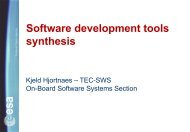
IMCM Demonstration Application The following figure illustrates the actuator position order and achievedposition, as measured by the embedded lvdt, during a 2.5 Hz frequencyresponse test.0.40.30.20.100 50 100 150 200 250 300 350 400 450 500 550 600 650 700 750 800 850 900 950 1000 1050 1100 1150 1200 1250 1300 1350 1400 1450 1500 1550 1600-0.1-0.2-0.3-0.4Time in ms; Amplitudes in mmTN0342-Iss10.pptAll right reserved: Disclosure to third parties of this document or any part thereof, or the use of any information contained therein for purposes other than provided for by this document, is not permitted exceptwith prior and express written permission of S.A.B.C.A.06/12/200446
HBRISC2 Perspectives Current and coming applications VEGA Tip-tilt mechanism GSTP3 HPEA GSTP4 Reaction Sphere Development environment Towards HBRISC2 Application+ ToolTN0342-Iss10.pptAll right reserved: Disclosure to third parties of this document or any part thereof, or the use of any information contained therein for purposes other than provided for by this document, is not permitted exceptwith prior and express written permission of S.A.B.C.A.06/12/200447
VEGA TVC IPDUAVUMZ 9Z 23P 80EM TVC isEMA + IPDU +BSTN0342-Iss10.pptAll right reserved: Disclosure to third parties of this document or any part thereof, or the use of any information contained therein for purposes other than provided for by this document, is not permitted exceptwith prior and express written permission of S.A.B.C.A.06/12/200448
Tip-Tilt Mechanism, a CSEM Application 3-axis Tip-Tilt Mechanism demonstrator supporting a mirror and basedon CSEM innovative flexure structure technology (FLEXTEC) 3-axis control is implemented with one single HBRISC-2 First SABCA activity/experience as “HBRISC-2 provider” Evaluate fine pointing potential of HBRISC-2 Have external feed-back on HBRISC-2 circuit and developing environmentTN0342-Iss10.pptAll right reserved: Disclosure to third parties of this document or any part thereof, or the use of any information contained therein for purposes other than provided for by this document, is not permitted exceptwith prior and express written permission of S.A.B.C.A.06/12/200449
GSTP3 HPEA & GSTP4 Reaction Sphere, a CSEM Application GSTP-3 HPEA: High Power Electrical Actuation for Solid RocketBoosters Goal: validate technologies that could be used in a Solid Rocket Booster highPower Electro Mechanical Thrust Vector Control (EMTVC) Premise of ARIANE 2010 HBRISC2 is part of the 50kW motor drive demonstrator: Direct drive Power sharing between axes Redundant controller GSTP-4 Reaction Sphere – under negotiation – Support to BRISC Expertise in asynchronous motor available (VFC application) Possible companion activities: see next slides on development tools potentialupgradesTN0342-Iss10.pptAll right reserved: Disclosure to third parties of this document or any part thereof, or the use of any information contained therein for purposes other than provided for by this document, is not permitted exceptwith prior and express written permission of S.A.B.C.A.06/12/200450
Towards HBRISC2 Application+ ToolFirst real applications (VEGA TVC & Tip-Tilt) havehighlighted that a continuous evolution of HBRISC2 toolsis required: To cover wider application ranges To develop fasterPotential evolutions include: HBRISC2 debugger Synthesizer+ (“single-model/multi-binary” architecture) Enhanced Win32-Seracq and HSSL-SPI I/FTN0342-Iss10.pptAll right reserved: Disclosure to third parties of this document or any part thereof, or the use of any information contained therein for purposes other than provided for by this document, is not permitted exceptwith prior and express written permission of S.A.B.C.A.06/12/200451
IMCM ConclusionHBRISC2 and its development tools, Synthesizer andlibraries were successfully developed and validated inthe frame of this GSTP2 IMCM projectThe circuit and its tools are already part of severalapplications: The flight critical VEGA launcher TVC, on all four stages Complex demonstration applications with CSEM More contacts are on-goingEvolution towards even more efficient development toolsare already plannedTN0342-Iss10.pptAll right reserved: Disclosure to third parties of this document or any part thereof, or the use of any information contained therein for purposes other than provided for by this document, is not permitted exceptwith prior and express written permission of S.A.B.C.A.06/12/200452