TCSPC for FLIM and FRET in - Boston Electronics Corporation
TCSPC for FLIM and FRET in - Boston Electronics Corporation
TCSPC for FLIM and FRET in - Boston Electronics Corporation

You also want an ePaper? Increase the reach of your titles
YUMPU automatically turns print PDFs into web optimized ePapers that Google loves.
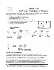
It has been shown that diode lasers can be used <strong>for</strong> time-resolved microscopy with good results [33,33a]. Un<strong>for</strong>tunately the beam quality of diode lasers is not very good. There<strong>for</strong>e it can be difficult toobta<strong>in</strong> a diffraction-limited resolution. However, if only the central part of the beam is used, theresult can be quite acceptable. Discard<strong>in</strong>g a large fraction of the beam causes a considerable loss ofpower. This loss is, however, not substantial because 50 µW <strong>in</strong> the focal plane are sufficient toexcite the sample.Modulated CW LasersFor signal process<strong>in</strong>g techniques based on phase measurement of modulated signals CW Ar+ <strong>and</strong>HeNe lasers <strong>in</strong> conjunction with an acousto-optical modulator can be used. However, care must betaken to avoid any crosstalk of the modulation frequency <strong>in</strong>to the detection system. The smallestamount of crosstalk makes an accurate phase measurement impossible.Us<strong>in</strong>g modulated CW lasers <strong>in</strong> conjunction with photon count<strong>in</strong>g techniques is not recommended.These techniques require pulses rather than s<strong>in</strong>ewave signals. Acousto-optical modulators areresonance systems unable to deliver sufficiently short pulses with high on/off ratio.Mode-locked CW LasersAr+ lasers can be actively mode-locked. By <strong>in</strong>troduc<strong>in</strong>g a modulator <strong>in</strong>to the laser cavity pulses asshort as 100 ps with 80 to 120 MHz repetition rate are obta<strong>in</strong>ed. The pulses can be used directly orto pump a jet-stream dye laser that delivers ps pulses at a wavelength tuneable from 500 to 600 nm .Although the light from these lasers can be used <strong>for</strong> fluorescence excitation [65] the systems areoften unstable <strong>and</strong> require permanent ma<strong>in</strong>tenance, check<strong>in</strong>g <strong>and</strong> re-adjustment. We stronglydiscourage to use these lasers as excitation sources <strong>for</strong> time-resolved microscopy.Pulse Pickers <strong>and</strong> Cavity DumpersPulse pickers <strong>and</strong> cavity dumpers are used to obta<strong>in</strong> a lower repetition rate from lasers runn<strong>in</strong>g at ahigh, fixed repetition rate. For fluorescence measurements they are sometimes used to measurelifetimes longer than the orig<strong>in</strong>al period of the laser. The problem of the devices is the poor on-offratio <strong>and</strong> the electrical noise they often produce. It is by far better to take some <strong>in</strong>complete decay<strong>in</strong>to regard <strong>in</strong> the data analysis than to cope with electrical noise <strong>and</strong> satellite pulses. Furthermore, alow repetition rate reduces the useful count rate <strong>in</strong> photon count<strong>in</strong>g setups <strong>and</strong> possibly <strong>in</strong>creasesphotobleach<strong>in</strong>g. Don’t use pulse pickers if they are not absolutely necessary.DetectorsPhotomultiplier Tubes (PMTs)The most common detectors <strong>for</strong> low level detection of lightare photomultiplier tubes. A conventional photomultipliertube (PMT) is a vacuum device which conta<strong>in</strong>s aphotocathode, a number of dynodes (amplify<strong>in</strong>g stages) <strong>and</strong>Photoananode which delivers the output signal (fig. 9).CathodeD2D1D3D4D6D5D7D8 AnodeThe operat<strong>in</strong>g voltage builds up an electrical field thataccelerates the electrons from the photocathode to the firstFig. 9 Pr<strong>in</strong>ciple of a conventional PMTdynode D1, from D1 to D2, further to the next dynodes, <strong>and</strong>from D8 to the anode. When a photoelectron emitted from the photocathode hits D1 it releasesseveral secondary electrons. The same happens <strong>for</strong> the electrons emitted by D1 when they hit D2.The overall ga<strong>in</strong> reaches values of 10 6 to 10 8 . The secondary emission at the dynodes is very fast,there<strong>for</strong>e the secondary electrons result<strong>in</strong>g from one photoelectron arrive at the anode with<strong>in</strong> a few9