SUBCOURSE EDITION - Modern Prepper
SUBCOURSE EDITION - Modern Prepper
SUBCOURSE EDITION - Modern Prepper
Create successful ePaper yourself
Turn your PDF publications into a flip-book with our unique Google optimized e-Paper software.
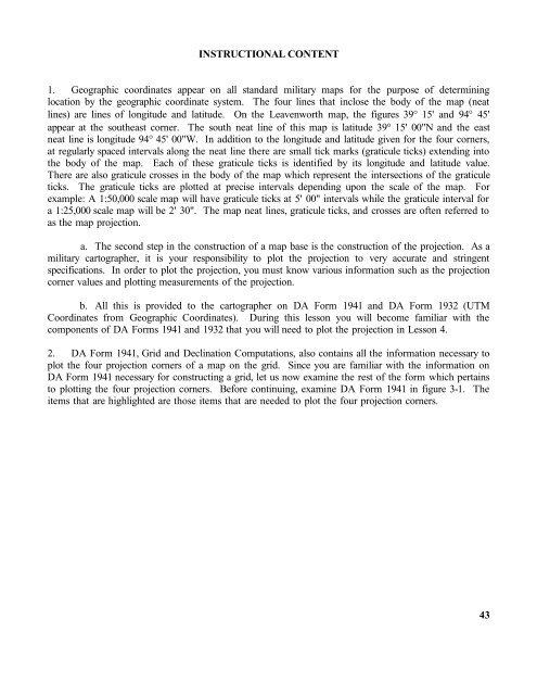
INSTRUCTIONAL CONTENT1. Geographic coordinates appear on all standard military maps for the purpose of determininglocation by the geographic coordinate system. The four lines that inclose the body of the map (neatlines) are lines of longitude and latitude. On the Leavenworth map, the figures 39° 15' and 94° 45'appear at the southeast corner. The south neat line of this map is latitude 39° 15' 00"N and the eastneat line is longitude 94° 45' 00"W. In addition to the longitude and latitude given for the four corners,at regularly spaced intervals along the neat line there are small tick marks (graticule ticks) extending intothe body of the map. Each of these graticule ticks is identified by its longitude and latitude value.There are also graticule crosses in the body of the map which represent the intersections of the graticuleticks. The graticule ticks are plotted at precise intervals depending upon the scale of the map. Forexample: A 1:50,000 scale map will have graticule ticks at 5' 00" intervals while the graticule interval fora 1:25,000 scale map will be 2' 30". The map neat lines, graticule ticks, and crosses are often referred toas the map projection.a. The second step in the construction of a map base is the construction of the projection. As amilitary cartographer, it is your responsibility to plot the projection to very accurate and stringentspecifications. In order to plot the projection, you must know various information such as the projectioncorner values and plotting measurements of the projection.b. All this is provided to the cartographer on DA Form 1941 and DA Form 1932 (UTMCoordinates from Geographic Coordinates). During this lesson you will become familiar with thecomponents of DA Forms 1941 and 1932 that you will need to plot the projection in Lesson 4.2. DA Form 1941, Grid and Declination Computations, also contains all the information necessary toplot the four projection corners of a map on the grid. Since you are familiar with the information onDA Form 1941 necessary for constructing a grid, let us now examine the rest of the form which pertainsto plotting the four projection corners. Before continuing, examine DA Form 1941 in figure 3-1. Theitems that are highlighted are those items that are needed to plot the four projection corners.43


