


You also want an ePaper? Increase the reach of your titles
YUMPU automatically turns print PDFs into web optimized ePapers that Google loves.
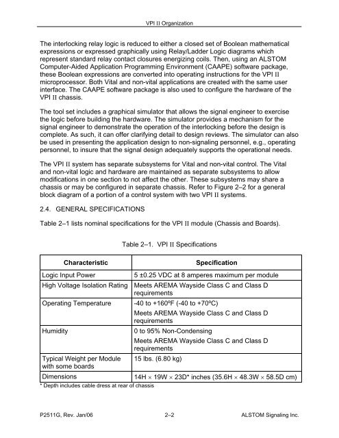
<strong>VPI</strong> <strong>II</strong> OrganizationThe interlocking relay logic is reduced to either a closed set of Boolean mathematicalexpressions or expressed graphically using Relay/Ladder Logic diagrams whichrepresent standard relay contact closures energizing coils. Then, using an ALSTOMComputer-Aided Application Programming Environment (CAAPE) software package,these Boolean expressions are converted into operating instructions for the <strong>VPI</strong> <strong>II</strong>microprocessor. Both Vital and non-vital applications are created with the same userinterface. The CAAPE software package is also used to configure the hardware of the<strong>VPI</strong> <strong>II</strong> chassis.The tool set includes a graphical simulator that allows the signal engineer to exercisethe logic before building the hardware. The simulator provides a mechanism for thesignal engineer to demonstrate the operation of the interlocking before the design iscomplete. As such, it can offer clarifying detail to design reviews. The simulator can alsobe used in presenting the application design to non-signaling personnel, e.g., operatingpersonnel, to insure that the signal design adequately supports the operational needs.The <strong>VPI</strong> <strong>II</strong> system has separate subsystems for Vital and non-vital control. The Vitaland non-vital logic and hardware are maintained as separate subsystems to allowmodifications in one section to not affect the other. These subsystems may share achassis or may be configured in separate chassis. Refer to Figure 2–2 for a generalblock diagram of a portion of a control system with two <strong>VPI</strong> <strong>II</strong> systems.2.4. GENERAL SPECIFICATIONSTable 2–1 lists nominal specifications for the <strong>VPI</strong> <strong>II</strong> module (Chassis and Boards).Table 2–1. <strong>VPI</strong> <strong>II</strong> SpecificationsCharacteristicSpecificationLogic Input Power5 ±0.25 VDC at 8 amperes maximum per moduleHigh Voltage Isolation Rating Meets AREMA Wayside Class C and Class DrequirementsOperating Temperature -40 to +160ºF (-40 to +70ºC)Meets AREMA Wayside Class C and Class DrequirementsHumidity0 to 95% Non-CondensingMeets AREMA Wayside Class C and Class DrequirementsTypical Weight per Module 15 lbs. (6.80 kg)with some boardsDimensions14H × 19W × 23D* inches (35.6H × 48.3W × 58.5D cm)* Depth includes cable dress at rear of chassisP2511G, Rev. Jan/06 2–2 ALSTOM Signaling Inc.


