FS Station – www.fsstation.comThat's the end of the descent and approach briefing. Please read this section again, analyze the approach platecarefully and get ready to start the descent. It is extremely important that you fully understand what you aresupposed to do before starting the descent.Since we've already briefed the descent and approach procedure, I'll not be very detailed here - much of the informationyou need for this phase were already presented in the briefing section. Back at cruise altitude, move the throttle to theflight idle position and wait for the speed to drop to 210 knots. Then, adjust the attitude and thrust so that you descendat -2000FPM with a constant speed of 210 knots. While descending, continue to track the ABILENE VOR 250 radial.From the approach plate, we learn that the decision height for this approach is 200 feet - set this in the radar altimeter.Continue the descent until reaching 5,000ft, then level-off and adjust the throttle to maintain 180 knots.Five miles past the VOR station, start a left turn to heading 341 in order to enter the downwind leg. The airport should beahead of you, on the left side. Slow down to 150 knots - that is the normal downwind leg speed. Still in the downwindleg, set the ILS frequency on the NAV1 radio (I-DYS - 109.90) and turn the COURSE SET knob to 161 (runway heading).Maintain this same heading, speed and altitude until the glideslope bar has moved all the way up. At this point, startanother left turn to the base leg (heading 71), reduce the speed to 140 knots and command flaps 50%. In a short time,the localizer will become "alive" - make your last left turn to the final approach leg, extend the landing gear and activatethe auxiliary hydraulic pump. Finally, command flaps 100% and reduce the speed to about 130 knots "when landing isassured". You may want to turn the taxi and landing lights on, also.Landing, taxiing and shutdown--- RUN THE BEFORE LANDING CHECKLIST ---You have successfully started the aircraft and flown it for about 1h30min, it's finally time to land. We'll now get to therunway and touchdown at the right speeds, taxi to the stand and shutdown the aircraft.Continue tracking the localizer and glideslope, but also keep an eye on the runway - it's important that you have visualcontact with it before reaching the decision height. At about 1000 feet above ground level (watch the radio altimeter),reduce the power slightly so that you can slow down to the threshold speed. When above the threshold, reduce thepower once last time so that you can reach the touchdown speed at the moment of touchdown. Keep a close eye on theradio altimeter, the speed, the attitude indicator and the runway. At about 25 feet above ground level, pull back on theyoke to begin the flare - your vertical speed should now be -100~200FPM, which is perfectly suitable for landing. Don'tworry if the conditions require a greater vertical speed, the landing gear can handle rough landings too.Touchdown with the main gear first and smoothly apply forward pressure to lower the nose gear and increase steeringeffectiveness. Brake the aircraft and apply reverse thrust as needed. At taxi speed, release the brakes and move thethottles forward to maintain taxi speed; exit the runway and start taxiing to the stand following ATC instructions. Whiletaxiing, command flaps up and:- In the IFF/SSR panel (SSR icon):1. Turn the Master Control knob to the STBY positionThe transponder is no longer needed now that you're on the ground again.FS Station – www.fsstation.comPage 16 of 20
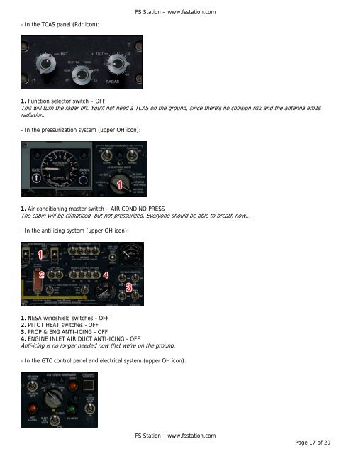
FS Station – www.fsstation.com- In the TCAS panel (Rdr icon):1. Function selector switch – OFFThis will turn the radar off. You'll not need a TCAS on the ground, since there's no collision risk and the antenna emitsradiation.- In the pressurization system (upper OH icon):1. Air conditioning master switch – AIR COND NO PRESSThe cabin will be climatized, but not pressurized. Everyone should be able to breath now...- In the anti-icing system (upper OH icon):1. NESA windshield switches - OFF2. PITOT HEAT switches - OFF3. PROP & ENG ANTI-ICING - OFF4. ENGINE INLET AIR DUCT ANTI-ICING - OFFAnti-icing is no longer needed now that we're on the ground.- In the GTC control panel and electrical system (upper OH icon):FS Station – www.fsstation.comPage 17 of 20