Model 24923 Installation Guide - Ready Remote
Model 24923 Installation Guide - Ready Remote
Model 24923 Installation Guide - Ready Remote

Create successful ePaper yourself
Turn your PDF publications into a flip-book with our unique Google optimized e-Paper software.
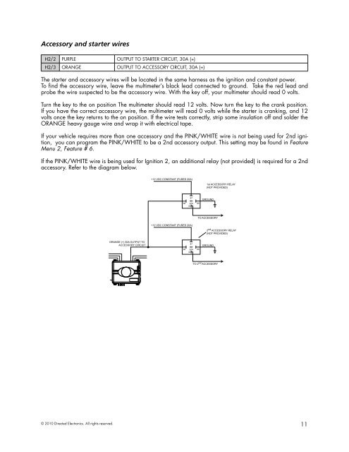
Accessory and starter wiresH2/2 PURPLE OUTPUT TO STARTER CIRCUIT, 30A (+)H2/3 ORANGE OUTPUT TO ACCESSORY CIRCUIT, 30A (+)The starter and accessory wires will be located in the same harness as the ignition and constant power.To find the accessory wire, leave the multimeter’s black lead connected to ground. Take the red lead andprobe the wire suspected to be the accessory wire. With the key off, your multimeter should read 0 volts.Turn the key to the on position The multimeter should read 12 volts. Now turn the key to the crank position.If you have the correct accessory wire, the multimeter will read 0 volts while the starter is cranking, and 12volts once the key returns to the on position. If the wire tests correctly, strip some insulation off and solder theORANGE heavy gauge wire and wrap it with electrical tape.If your vehicle requires more than one accessory and the PINK/WHITE wire is not being used for 2nd ignition,you can program the PINK/WHITE to be a 2nd accessory output. This setting may be found in FeatureMenu 2, Feature # 6.If the PINK/WHITE wire is being used for Ignition 2, an additional relay (not provided) is required for a 2ndaccessory. Refer to the diagram below. © 2010 Directed Electronics. All rights reserved.11