Model 24923 Installation Guide - Ready Remote
Model 24923 Installation Guide - Ready Remote
Model 24923 Installation Guide - Ready Remote

You also want an ePaper? Increase the reach of your titles
YUMPU automatically turns print PDFs into web optimized ePapers that Google loves.
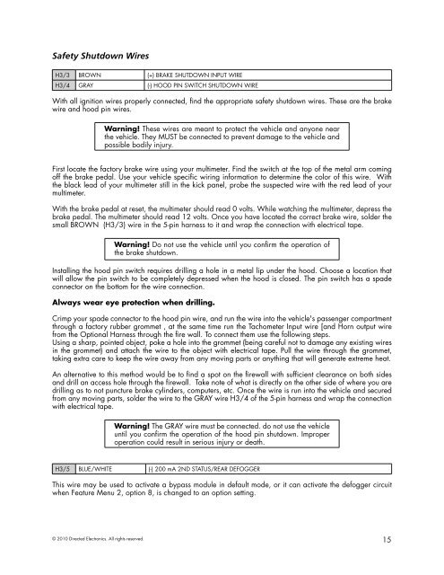
Safety Shutdown WiresH3/3 BROWN (+) BRAKE SHUTDOWN INPUT WIREH3/4 GRAY (-) HOOD PIN SWITCH SHUTDOWN WIREWith all ignition wires properly connected, find the appropriate safety shutdown wires. These are the brakewire and hood pin wires.Warning! These wires are meant to protect the vehicle and anyone nearthe vehicle. They MUST be connected to prevent damage to the vehicle andpossible bodily injury.First locate the factory brake wire using your multimeter. Find the switch at the top of the metal arm comingoff the brake pedal. Use your vehicle specific wiring information to determine the color of this wire. Withthe black lead of your multimeter still in the kick panel, probe the suspected wire with the red lead of yourmultimeter.With the brake pedal at reset, the multimeter should read 0 volts. While watching the multimeter, depress thebrake pedal. The multimeter should read 12 volts. Once you have located the correct brake wire, solder thesmall BROWN (H3/3) wire in the 5-pin harness to it and wrap the connection with electrical tape.Warning! Do not use the vehicle until you confirm the operation ofthe brake shutdown.Installing the hood pin switch requires drilling a hole in a metal lip under the hood. Choose a location thatwill allow the pin switch to be completely depressed when the hood is closed. The pin switch has a spadeconnector on the bottom for the wire connection.Always wear eye protection when drilling.Crimp your spade connector to the hood pin wire, and run the wire into the vehicle's passenger compartmentthrough a factory rubber grommet , at the same time run the Tachometer Input wire [and Horn output wirefrom the Optional Harness through the fire wall. To connect them use the following steps.Using a sharp, pointed object, poke a hole into the grommet (being careful not to damage any existing wiresin the grommet) and attach the wire to the object with electrical tape. Pull the wire through the grommet,taking extra care to keep the wire away from any moving parts or anything that will generate extreme heat.An alternative to this method would be to find a spot on the firewall with sufficient clearance on both sidesand drill an access hole through the firewall. Take note of what is directly on the other side of where you aredrilling as to not puncture brake cylinders, computers, etc. Once the wire is run into the vehicle and securedfrom any moving parts, solder the wire to the GRAY wire H3/4 of the 5-pin harness and wrap the connectionwith electrical tape.Warning! The GRAY wire must be connected. do not use the vehicleuntil you confirm the operation of the hood pin shutdown. Improperoperation could result in serious injury or death.H3/5 BLUE/WHITE (-) 200 mA 2ND STATUS/REAR DEFOGGERThis wire may be used to activate a bypass module in default mode, or it can activate the defogger circuitwhen Feature Menu 2, option 8, is changed to an option setting.© 2010 Directed Electronics. All rights reserved.15