HTNVY.DUTY CIRCULAR SNWS T ITSTNII ... - Wood Tools
HTNVY.DUTY CIRCULAR SNWS T ITSTNII ... - Wood Tools
HTNVY.DUTY CIRCULAR SNWS T ITSTNII ... - Wood Tools

You also want an ePaper? Increase the reach of your titles
YUMPU automatically turns print PDFs into web optimized ePapers that Google loves.
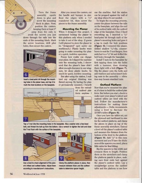
---7\v llTurn the frameassembly upsidedown to glue and;;;; i,ounti,,g// block in place. Next,// posinon the casters,,4 keepinsthem atleast 2rlaway from the rails toavoid the screws you justdrove through the rails into theends of the mounting block. Markthe screw locations, drill pilotholes. then secure the casters.Insert a brad-point bit ttrrcugh the mountingholes in the planer base, and bp it tomad< the hole locations on the baseplab.After you mount the casters, cutthe handle and bumper to size.Rout the edges with a r/zuroundover bit, then screw thepieces to the frame assembly.Mounfing fhe PlonerWhen I designed this project, Ienvisioned bolting the planer tothis plafform only when I neededto take it out of the shop. (I guessI still planned to store the planer inits "designated" spot under myworkbench.) Plastic knobs weregoing to make mounting the planera quick, tool-free operation.Funny how reality can changeyourplans. fu I slipped the machineonto the mounting bolts, I discoveredthat the planer's base didn'tallow enough clearance to use wingnuts,let alone plastic knobs. Somuch for quick, tool-free mounting.But after using the station, I realizedmy original thinking wasflawed anyway. By having the planerpermanently mounted, I benefitTap a T-nut into the mounting holes in the baseplate. Slip a washer onb a har-headbolt, and thread the bolt up fiom the bottom. Use a wrench to tighbn the bolt and drawthe T-nut flush with the surface of the baseplate.Use a lerel b check alignment of the plane/sinfted and outfeed hbles, Adjusthemaccording to manuhcturc/s instructions,from the extendedoufeed platformanytime IClamp the platform pieces in place, thenmeasurc betrveen them and the outfeeitable to determine spacer height.use the machine. And the stationcan be propped against the wall ofmy shop when ifs not needed.'To begin the mounting process,center the planer between the railson the baseplate, and align the endof its ouffeed table with the oufeededge of the baseplate. Once I linedeverything up, I inserted a 3/stbrad-point bit through each of theplaner's mounting holes and gave ita tap to mark the hole positions(Figure 6). I removed the planer,drilled shallow 3/4tt-dia. counterboresto seat the T:-nut flanges, thenswitched to a3 /s" bit and drilled thebolt holes through the baseplate.Install T-nuts in the baseplate byfirst tapping them into the holeswith a hammer, then drawingthem tight with a bolt (Figure 7).Slip the planer onto the bolts andadd washers and nylon-insert lockingnuts to the assembly - vibrationmay loosen standard nuts.Outfeed PlotformNow that you've mounted the planer,ifs time to build the ouffeed platform.But before you start, check tomake sure your planer's infeed andouffeed tables are level with thebed. Follow the manufacturer'sinstructions for making theseadjusffnents - Delta recommendsusing a level to fine-tune the22-560's tables (Figure 8).Once you have the tables set, cutthe plywood and hardboard to sizefor the oufeed plafform, and clampthe pieces in place on top of theframe assembly sfetchers. Extenda level off the planer's ouffeed tableand measure the distance from thebottom of the level to the plafform(Figure 9). Add Vs'r to this measurementand you'll have the thicknessofthe spacers you need, plus alittle extra for final fitting.Rip the spacers to this width andcrosscut them to length. Positionthem on the stretchers and clampthe pladorm panels in place, makingsure their ends butt againstthe planer's ouffeed table. Lay astraightedge across the ouffeedtable and the plafform to see how56\Torkbench I June 1998


![Til]tl](https://img.yumpu.com/45878240/1/190x245/tiltl.jpg?quality=85)