CONVENTIONAL FIRE PANELS - Kotesa
CONVENTIONAL FIRE PANELS - Kotesa
CONVENTIONAL FIRE PANELS - Kotesa
- No tags were found...

Create successful ePaper yourself
Turn your PDF publications into a flip-book with our unique Google optimized e-Paper software.
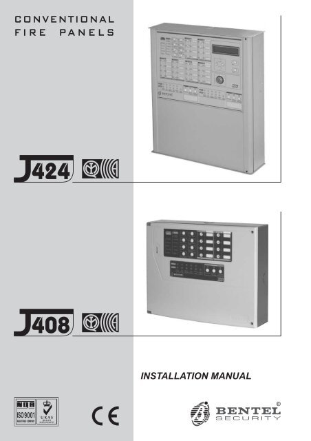
<strong>CONVENTIONAL</strong><strong>FIRE</strong> <strong>PANELS</strong>424408INSTALLATION MANUAL®
This Control panel can be programmed using the respective Software J400 release 1.0 or higher.BENTEL SECURITYsrl shall not assume the responsibility for damage arising from improper application or use.This Control panel has been designed and manufactured to the highest standards of quality and performance.Installation of this Control panel must be carried out strictly in accordance with the instructions described in this manual, andin compliance with the local laws and bylaws in forceThe J424 and J408 Control panels comply with the essential requirements of standards EN54-2; EN54-4.The J424 and J408 Control panels, all their accessories and functions, except those listed below and unless otherwise specified(see notes marked A), are IMQ Security Systems Grade II Listed.The J400-EXT Extinguishment Module is not IMQ Security Systems Grade II Listed.BENTEL SECURITY srl reserves the right to change the technical specifications of these products without prior notice.
TABLE OF CONTENTSINTRODUCTION 5The J424 and J208 Control panels 5Accessory Items 5Description 5Inputs 5Outputs 6Operating features 6Interface 7Extinguishment Module 8Access to Signalling and Commands 8Power Supply 8IDENTIFICATION OF PARTS 9The Status LEDs 9Description of Parts 14Description of the Control keys 20INSTALLING THE CONTROL PANEL 21Installing accessory boards 21Installing Extinguishment Modules 21Installing Expander Module Kit (for J424 ONLY) 22Display Module (for J424 and J400-REP ONLY) 24Installing Repeaters 25Installing the Control panel 25Description of the Terminals 25Main Board and Expander Board terminals 25Main Board Terminals 26Extinguishment Module Terminals 28Extinguishment Module 4Pre-extinguishment Phase 5Extinguishment Phase 5Manual Extinguishment 5Disable Extinguish. button 5Disable Manual Extinguish. button 5The System Wiring 29Connecting Fire Detectors 29Connecting Call-points 30Connecting Gas Detectors 30Connecting Signalling Devices 31Connecting a Repeater 32Connecting Extinguishment Modules 33Connecting a Power Supply 34Connecting the Mains Supply 34Thermal Probe 35Maintenance 35
PROGRAMMING FROM A PC 37Enrolling: Expander Modules 37Enrolling: Extinguishment Modules 37Activation Mode 38Times 38Zones 38Manual Extinguishment Input 38Disable Extinguishment Input 38Pressure Switch Input 38Enrolling: Power Supply Stations 38Enrolling: Repeaters and LCD Modules 38Zones 39Thresholds 39Options 40Times 40Outputs 40NAC1 Output 40NAC2 Output 40ALARM Output 40OC Output Events 41DL Output 41Panel Settings 41Day/Night 41Reset 42User Code 42Alarm Verification Time 42Night Mode Silence Time 42Mains Failure Signalling Delay 42Date/Time 42Downloading 43PROGRAMMING FROM THE PANEL 45Accessing the Programming session 45Exiting the Programming Session 45The “ZONES” Programming Phase 46The “TIMES” Programming Phase 46The “OUTPUTS” Programming Phase 47The “PANEL” Programming Phase 48User Code (Key/LED 1) 48Day Mode (Key/LED 2) 48Night Mode (Key/LED 4) 48Clock (Key/LED 5) 48Date (Key/LED 7) 48Mains Off Delay (Key/LED 8) 48The “VARIOUS” Programming Phase 48Stabilization Time (Key/LED 1) 49Reset Time (Key/LED 2) 49Silenceable Outs (Key/LED 4) 49Configuration 1 (Key/LED 5) 49Configuration 2 (Key/LED 7) 49The “MODULES” Programming Phase 49Extinguish. time (Key/LED 1) 49Pre-exting. time (Key/LED 2) 50Activation Zones (Key/LED 4) 50LCD Module 50Programming Mode Address 50Zones Descriptions 50Strings Update 50Date Format 50QUICK GUIDE 51Technical features 51Description of the terminals 51
INTRODUCTIONThe J424 and J208 Control panelsThe reduced complexity J424 and J408 Fire Controlpanels are the fruit of attentive research and installerperception. The winning combination of expert workmanship,high quality materials and essential linksamong vital components provide maximum installationflexibility and performance.The components of these Control panels operate as intendedwhen the external ambient conditions complywith the requirements of class 3k5 of IEC 721-3-3:1978.The J424 and J408 Control panels provides the followingfeatures: 8 Supervised/Bypassable input zones(the J408-2 provides 2 and the J408-4provides 4);2 Supervised/Silenceable/Bypassable fire outputs;1 Silenceable fire output and 1 Silenceable/Bypassablefault alarm output.The J424 model has been especially designed for mediumto large residential and commercial applications.It supports two 8 zone Expander Modules (providing atotal of 24 zones); two Extinguishment Modules and anLCD Module and provides housing for two 12 V, 17 Ahbatteries. This model is powered by a 2.5 A switchingpower supply.The J408 model has been especially designed for smallresidential and commercial applications. It is availablewith2(TJ408-2),4(J408-4) or 8 zones (J408-8).It supports 1 Extinguishment Module and provides housingfor two 12 V, 7 Ah batteries. This model is poweredby a 1.5 A switching power supply. Accessory ItemsJ400-EXP8 Expander Module Kit. This kit comprisesan 8 zone Expander Module and an Expander Controlboard. The Expander Module contains most of theelectronic circuitry and electrical terminals whereas theExpander Control board provides the command keysand status LEDs of the Expander Module zones.The Expander Module and Expander Control board areintended for connection to the Main board of the Controlpanel. In the event of an alarm, the Expander Modulewill signal the status of its inputs to the Main boardwhich will activate the fire warning and fire control devicesand generate signalling on the Expander Controlboard. The J424 accepts TWO J400-EXP8 ExpanderModules Kits.J400-EXT Extinguishment ModuleFalse activation of fire extinguishment devices may causeunnecessary inconvenience to end-users and seriousdamage to property. The J400-EXT ExtinguishmentModule aims at the reducing the false alarm rateby verifying alarm conditions before activating the extinguishmentdevices.The J408-8, J408-4 and J408-2 Control panels supportONE Extinguishment Module Kit, whereas the J424Control panel supports TWO.A The J400-EXT Extinguishment Module IS NOT anIMQ-SECURITY SYSTEMS listed product.J400-LCD Display ModuleThis board has 6 scroll keys and a two-line backlit LCD(16 characters per line) which provides written informationregarding the system status.J400-REP Repeater panelThis Repeater panel is intended for connection (via 4wires) to J424 and J408-8 Control panels. It provides allthe visual and audible warnings generated by the Controlpanel and allows end-users to manage the systemfrom a remote location (up to 1000 metres from theControl panel). The J424 and J408-8 Control panelssupport up to FOUR Repeater panels.Software Management SofwareThis user-friendly software application (Windows) offersa quick and easy way to program the Control paneland provides event logger and print-out functions.Description InputsThis Control panel has special inputs (detection zones)for fire detection devices, such as conventional fire detectors(i.e. devices which resemble the operatingmode of open contacts during standby status and resistorsduring Alarm status) and similar devices, such asCallpoints and gas detectors.The Control panel considers its inputs to be in standbystatus when they pull-down to 0 V with a 3900 ohm resistance.The inputs can detect and signal AutomaticAlarms (generated by fire detectors), Manual Alarms(generated by Callpoints), shorted lines (generated bydetector faults) and interrupted lines (generated by theremoval of detectors from their bases).INTRODUCTION 5
A IMQ-SECURITY SYSTEMS certification appliesONLY when no more than 30 devices are connectedto each zone, and no more than 512 devices INALL are connected to the Control panel. OutputsA This Control panel accepts devices that operatewithin SELV limits ONLY.This section describes how the Control panel outputsoperate.Supervised outputs The Control panel will be able todetect and signal short-circuits and power supply interruptionson this type of output.Bypassable outputs The user will be able to disable(by means of the respective key) this type of output.Silenceable outputs The user will be able to stop (viathe Silence key) this type of outputThe outputs can be silenced for an indefinite period (duringDay Mode) or, for the programmed Silence Time(during Night Mode).This Control panel provides the following alarm outputs: two Supervised/Silenceable/Bypassable outputs(NAC1 and NAC2 terminals) with positive polarity(27.6 V) during alarm status; one Silenceable/NON-Supervised/NON-BypassableVolt-free changeover contact (ALARM terminals) fordevices which cannot be connected directly to NAC1or NAC2; one Supervised/Bypassable/NON-Silenceable output(DL terminal), intended for use with telephone devicesthat pull-down to 0 V (negative) in the event of an alarm; one Silenceable/NON-Supervised/NON-Bypassableoutput for each input zone (terminals R1, R2, ..., R8)that will pull-down to 0 V (negative) when the respectivezone generates an alarm. These outputs allow selectiveaction, as they activate only the devicesconnected to the zone concerned.The NAC1, NAC2 and DL outputs comply withEN54-2.This Control panel also provides: one Silenceable/NON-Supervised/NON-BypassableVolt-free changeover contact (TROUBLE terminals)that will activate in the event of trouble; one NON-Supervised/NON-Bypassable/NON-Silenceableopen-collector output (OC terminal) that willpull-down to 0 V (negative) when the associatedevent occurs (Alarm, Pre-alarm, Fault, Reset,Bypass, Test or Double knock); one NON-Supervised/NON-Bypassable/NON-Silenceablechangeover contact (PL terminal) that willpull-down to 0V(negative) in the event of power failureto the Control panel. Operating featuresPre-alarm If a zone generates an alarm during DayMode (Night Mode LED OFF), the Control panel will startthe Pre-alarm Time. This status will be signalled by: a slow intermittent beep; blinking on the LED of the Zone Alarm that generatedthe Alarm; glowing on the Pre-al. LED; activation of the NAC1 and NAC2 outputs — in accordancewith programming; Negative pull-down to 0VontheR terminal of thezone that generated the Alarm, that is, if thePre-alarm on R output option is enabled; Negative pull-down to 0 V on OC terminal, that is, if itis programmed to signal Pre-alarm.This Control panel will generate an Instant Alarm ifalarm conditions are detected during Night Mode(Night Mode LED glowing) or, if an alarm is triggeredfrom a Callpoint connected to a zone enabledfor Call point Priority (i.e. the Call point Priorityoption ENABLED).During Pre-alarm status, all persons on the premises(Access Level 1 — refer to “Access to signalling andcommands”) will be able to: activate an Evacuation Alarm by pressing and holdingthe Ack./Evac. key for AT LEAST 5 seconds.During Pre-alarm status, Key and PIN Code users(Access Level 2 — refer to “Access to signalling andcommands”) will be able to: add the Investigation Time to the Pre-Alarm Timeby pressing (for LESS THAN 5 seconds) theAck./Evac. key; activate an Evacuation Alarm by pressing and holdingthe Ack./Evac. key for AT LEAST 5 seconds; stop the Silenceable outputs and interrupt thePre-alarm Time by pressing the Silence key.During Silence status (Silence LED glowing), it is possibleto use the Silence key to release the Silenceableoutputs and restart Pre-alarm Time or, use the Resetkey to restore standby status.If the Control panel is operating in Night Mode(Night Mode LED glowing), the Control panel willexit Silence status automatically when the programmedNight mode Silence time expires.Alarm The Control panel will generate an alarm when thePre-Alarm Time expires. Alarm status will be signalled by: a fast intermittent beep; glowing on the LED of the Zone Alarm that generatedthe Alarm; glowing on the Alarm LED; activation of the NAC1 and NAC2 outputs — in accordancewith programming; Negative pull-down to 0VontheR terminal of thezone that generated the Alarm; Negative pull-down to0VontheOC terminal, that is,if it is programmed to signal Alarm status.6 Conventional Fire Panels J424/J408
The Control panel will activate the DL output whenthe programmed Alarm Signalling delay expires.During Alarm status, Key and PIN Code users (AccessLevel 2 — refer to “Access to signalling and commands”)will be able to: stop the Silenceable outputs by pressing the Silencekey.During Silence status (Silence LED glowing), it is possibleto use the Silence key to release the Silenceableoutputs, and the Reset key to restore standby status.If the Control panel is in Night Mode (Night ModeLED glowing), the Control panel will exit Silencestatus when the programmed Night mode Silencetime expires.Trouble This Control panel can detect and signal thefollowing Trouble: Input zone shorted or open; Supervised zone shorted or open; Control panel blocked; Output 24V or 24R shorted; Low battery, battery trouble or disconnected battery; Ground fault; Communication trouble with peripherals; Mains failure.Fault conditions will be signalled by: a slow intermittent beep (at 1 second intervals); glowing on the Fault LED; fast blinking on the LED of the “component” concerned(the Logic Unit LED will glow to signal “Controlpanel blocked”); activation of the Fault output (TROUBLE terminals); Negative pull-down to 0 V on OC terminal, that is, if itis programmed to signal Fault.The Fault output (TROUBLE terminals) and OC outputs(if duly programmed) will restore to standby automaticallywhen fault conditions clear.Under certain circumstances, fault conditions may clearspontaneously, if this occurs, the event will be stored inthe memory until the Control panel Resets.Stored Fault events will be signalled by: slow blinking on the LEDs of the “component” concerned.Silence This Control panel provides a Silence keywhich can be used to restore the Silenceable outputs tostandby status: R1, R2, ..., R8 NAC1 and NAC2 ALARM TROUBLESilence status will be signalled by: an audible signal (lasting 1 second) followed by along pause (lasting 5 seconds); glowing on the Silence LED.Silence status will be held until the Silence key is pressedagain or, if the Control panel is operating in NightMode, until the programmed Night mode Silence timeexpires, or until a new Alarm or Trouble condition is detected.ONLY Key and PIN Code Users (Access Level 2)can SILENCE the Silenceable outputs.Disable This Control panel provides keys which can beused to disable the bypassable inputs and outputs: Z1, Z2, ... Z24 can be used to bypass (exclude) theirrespective zones; Disab./Fault NAC can be used to bypass outputsNAC1 and NAC2; Disab./Fault Telecom can be used to bypass the DLoutput.DISABLED zones cannot generate alarms or warningsof any kind, and DISABLED outputs cannot be activated.Disabled status will be signalled by: glowing on the Disab. LED; glowing on the LED of the respective zone or output(see LEDs: Disabled/Fault/Test, Disab./Fault NACand Disab./Fault Telecom).ONLY Key and PIN Code Users (Access Level 2)can DISABLE zones and/or outputs.Reset Resetting the Control panel will restore the outputsto standby status, delete the memory, and interruptthe power supply to terminals Z1, Z2, ..., Z8 and 24R forthe programmed Reset Time.ONLY Key and PIN Code Users (Access Level 2)can Reset the system. Fire alarms must be Silenced(via the Silence key) before Reset.Fault conditions can be Reset directly (via the Resetkey). InterfaceVisual Signalling The system status will be signalledon the Control panel LEDs as follows:GREEN indicates normal operating conditions;AMBER indicates specific operating modes (for exampleDay or Night mode), and/or Fault conditions;RED indicates Alarm conditions.Memory The Control panel will signal Alarm/Faultevents until the system Resets, even if the event clearsin the meantime.Stored events will be signalled by: slow blinking on the LED concerned.Display The J424 Control panel can house theJ400-LCD Module. This module provides written informationregarding the system status, and the cause offaults on inputs and outputs (short-circuit, interruptionetc.).INTRODUCTION 7
Audible Signalling The Buzzer will signal the Controlpanel status as follows:Status Sound Pause DescriptionPre-alarm 0.5 s 0.5 s Intermittent beepAlarm 0.2 s 0.2 s Fast Intermittent beepFault 1 s 1 s Slow Intermittent beepSilence 1 s 5 sLong beep/Long pauseReset 0.5 s 0.1 sTest 1 s 3 sShort beep/ShortpauseLong beep/Long pauseTest This key will allow ALL users to test the Controlpanel Buzzer and LEDs (Access level 1), and Key andPIN Code Users to test the zones (Access level 2).To test a zone: press the respective Zone key (Z1,Z2, ...,Z24) and the Test key simultaneously. Extinguishment ModuleThis section describes how the J400-EXT ExtinguishmentModule operates.Activation Mode The Extinguishment devices may beactivated by alarm conditions on ONE of the programmedzones (OR Mode), at least TWO of the programmedzones (At least two Mode), or ALL of the programmedzones (ALL Mode).Pre-Extinguishment If the programmed ‘ActivationMode’ conditions occur, the Extinguishment Module willstart the Pre-Extinguishment phase (indicated by glowingon the Pre Ext. LED and by activation of the ModulePR outputs) but will not activate the respective Extinguishmentdevices immediately, thus allowing users toverify the Alarm.Extinguishment If the ‘Activation Mode’ conditionsare still present when the programmed Pre-Extinguishmenttime expires, the Extinguishment Module willactivate the Extinguishment phase (indicated by glowingon the Electrovalve LED and by the activation ofthe Module’s AE output). The Extinguishment devices,(connected to the Module’s EV output) will stay On untilthe alarm conditions cease, or until the programmedExtinguishment Time expires (i.e. if the Bistable optionis disabled), or until the Disable Extinguish. key ispressed.Auxiliary Supervision Inputs The ExtinguishmentModule provides supplementary supervision inputs forExtinguishment Inhibition, Manual Extinguishment andPressure Switch control. These Supervised inputsmust pull down to 0V(negative) with a 3.900 ohm resistanceduring standby status. In the event of interruptionor short-circuit, these inputs will generate a warningson the LED concerned. Access to Signalling and CommandsThere are 4 access levels, in compliance with the FireSafety Regulations in force.Access Level 1 Viewing: ALL persons can view theControl panel status.Access Level 2 Operating the system (PIN Code enteredor Key turned in the Keyswitch): ONLY Key and PINCode Users can operate the system.Access Level 3 Opening the Control panel: ONLYQualified persons with authorization are allowed toopen the Control panel door (requires removal of thescrews) for maintenance purposes.Access Level 4 Repairing or replacing the PCB:ONLY the Manufacturer should be allowed to repair orreplace the PCB. Power SupplyThe power supply system of the J424 and J408 Controlpanels complies with EN54-4.Both models are powered by the Mains (230 V, 50 Hz): the J408 model has Switching Power Supply whichsupplies up to 1.5 A at 27.6 V; the J424 model has Switching Power Supply whichsupplies up to 2.5 A at 27.6 V;Both models can house two 12 V batteries which, whenconnected in series, will supply 24 V to the Control paneland peripherals in the event of black-out, and willalso provide any pickup currents which exceed the maximumcurrent supplied by the Switching Power Supply.Power Supply: the J408 model can house two 7 Ah batteries (YUASANP 7-12 FR model or similar — flame class UL94-V2or higher); the J424 model can house two 17 Ah batteries(YUASA NP 17-12 FR model or similar — flame classUL94-V2 or higher).This Control panel can detect, signal and store in memorythe following power faults: shorted 24V or 24Routputs (24V/24R LED); Low battery, Battery fault orBattery disconnected (Battery LED), Ground fault(Ground LED) and Mains failure (Mains LED).The “Battery Disconnected” fault may be signalledwith a delay of up to 1 minute. The “Mains” fault willbe signalled when the programmed delay expires.8 Conventional Fire Panels J424/J408
IDENTIFICATION OF PARTSThe Status LEDsThe following section describes how the Control panelLEDs function.Some LEDs signal more than one condition, however,in most cases, the LEDs signal as follows:Glowing indicates Disabled status;Fast-blinking indicates a Fault condition;Slow-blinking (not mentioned in the table) indicates anAlarm in Memory.LEDDESCRIPTIONAlarm Glowing indicates Alarm status. In the event of an Alarm, the Control panel will activate the unbypassedalarm outputs..Pre-al. Glowing indicates Pre-alarm status.Test Glowing indicates Test conditions on at least one zone.Disab. Glowing indicates the Disabled status of the NAC,Telecom, Zone and Extinguishment outputs, or inhibitionof Manual or Automatic Extinguishment options.Telecom Glowing indicates that the Telephone device output is active (negative pull-down to 0Vonterminal[DL]).Green OFF indicates Mains failure (230 V).Mains IMPORTANT: Power must be restored before the batteries empty.Fault Glowing indicates one of the following Faults: Blocked Control panel; Shorted 24V or 24R output;Empty Batteries; Disconnected Battery; Ground Fault; Mains Failure; Zone Trouble; Shorted or OpenNAC or DL output; Extinguishment Module Trouble; Peripheral Trouble.Logic Unit Glowing indicates Blocked Control panel. IMPORTANT: Maintenance required24V/24R Fast blinking indicates Shorted 24V or 24R output.Battery Fast blinking indicates Batteries empty, disconnected or faulty. If this condition persists, the batterieswill be unable to function as intended in the event of blackout, therefore, replacement is required.Ground Fast blinking indicates a Voltage leakage to Earth.IMPORTANT: Check wiring insulation.Periph. Fast blinking indicates communication trouble with peripherals.Red Mains Fast blinking indicates Mains failure (230 V) or Switching Power supply fault. During this condition,the Control panel will be powered by the batteries. Mains failure is also signalled on the Green MainsLED (OFF), however, this LED also signals Mains Failure in Memory (Slow blinking).Silence Glowing indicates that Silenceable outputs (terminals [NAC1], [NAC2], [DL], [TROUBLE], [ALARM] (ifduly programmed) and [Rn] (if duly programmed) have been manually forced to standby by means ofthe respective key.Ack./Evac. Glowing indicates that the programmed Investigation time is running.Reset Glowing indicates that Reset operations cannot be carried out.Night Mode Glowing indicates that the Control panel is operating in Night Mode.Disab./FaultNACDisab./FaultTelecomGlowing indicates that the Supervised, Silenceable Fire Alarm outputs (terminals [NAC1] and[NAC2]) have been disabòled by means of the respective key, therefore, in the event of alarm will notbe activated.Fast blinking indicates that at least one of the Supervised, Silenceable Fire Alarm outputs (terminals[NAC1] and [NAC2]) is shorted or open.Glowing indicates that the telephone device output (terminal [DL]) has been disabled by means of therespective key, therefore, in the event of an alarm will not be activated.Fast blinking indicates that the telephone device output (terminal [DL]) is shorted or open.Disabled/ Glowing indicates that the respective zone has been disabled by means of the respective key, therefore,will be unable trigger alarms. Fast blinking indicates that the respective zone is shorted or open,Fault/Test therefore, unable to detect alarm conditions.Zone Alarm Glowing indicates that the respective zone has detected alarm conditions.Table 1 Description of the status LEDs ... (continued on page 20)
Zone AlarmAlarmPre-al.FaultLogicUnitSilence1 2 34Night Mode5z1z26TestBatteryAck./Evac.Disab./FaultNACDisab.Ground78TelecomMainsPeriph.MainsReset9Disab./FaultTelecom0Disab. BuzzerTestDisabled/Fault/TestMSACMNEIJ408-8 0.0MSACMBLIJ400-REP a.0b)4 1 5 4 1 2 2 44 1Zone Alarm24V/24Rz5z6z3z7z4z8Disabled/Fault/TestDisableONFaultElectrovalvePreExt.ManualExt.Disab.Ext.Pres.SwitchLogicUnitExtinguish. Manual AutomaticExtinguish. Extinguish.®MSACMBLIJ408-8 0.0408c.AlarmPre-al.TestDisab.FaultLogicUnit24V/24RBatteryGroundSilenceAck./Evac.Zone Alarm1 2 3z147Night ModeDisab./FaultNAC586z2z3Zone Alarmz5z6z7TelecomPeriph.ResetDisab./FaultTelecomLivello 2MainsMains90z4z8Disab. BuzzerTestDisabled/Fault/TestDisabled/Fault/TestBZone Alarmz9Zone Alarmz13z10z14z11z15Escz12Disabled/Fault/TestZone Alarmz17z16Disabled/Fault/TestZone Alarmz21Enter®z18z19z22z23400 REPz20Disabled/Fault/Testz24Disabled/Fault/Test44 5 34 2c)4IDENTIFICATION OF PARTS 11
NCNOC6 7 8 9 10 1131 3029Figure 2 Maximum configuration of the J424 Control panel282726
12 13 14 15 16 17 14 18 12 19NO NC C - + - +24R OC DL PL ALARM24V26+ -RS485TROUBLE NAC1 NAC227 28 29 30 31 NO NC CV24PRGFG AC/N AC/LGASB016EFF3.15A/25ØVB+LB–GND+VGND +VF6.3A/25ØVR1 2 3 4 5 6 7 8 9 10 11 12 13 14 15 16 17 18 19 20 21 22 23 24Z1 R1 Z2 R2 Z3 R3 Z4 R4 Z5 R5 Z6 R6 Z7 R7 Z8 R812 25 20 24232221 2012IDENTIFICATION OF PARTS 13
NCNOCDescription of PartsThis section describes the components of the J424 andJ408 Control panels, and J400-REP Repeater.Unless otherwise stated, the numbers in boldface in thisManual refer to the Tables ands Diagrams in this section.The parts identification numbers in the diagrams go clockwise.The white numbers refer to parts which are commonto several of the system devices, therefore, aredescribed the first time they are encountered only.P. Description1 Surface Cable conduit entry2 Zone label slots3 Display4 Door screws5 Keyswitch (Access Level 2)6 Display module (accessory item)7 Expander Control board (LEDs and keys) ofExpander no. 2 (accessory item for J424)8 Flat cable (accessory item for J424): for theExpander Control board connection9 Main Control board (LEDs and keys) of zones1 through 810 Expander Control board (LEDs and keys) ofzones 9 through 16 (accessory item forJ424)11 Flat cable: for the Main Control Board connection(zones 1 through 8)12 Anchor screw locations13 Main board (2, 4 or 8 zones)14 Chased cable conduit entry15 Flat cable (accessory item for J424): for theExpander Control board connection91128 3232 27Figure 3 Maximum configuration of the J408 Control panel14 Conventional Fire Panels J424/J408
P. Description16 Anchor for 230 V power supply wires17 Switching power supply screws18 Switching power supply/Battery charger19 Switching power supply support20 Batteries (NOT supplied!):J408 =two 7Ah@12VJ424 = two 17 Ah @ 12 V21 Expander no. 1 (accessory item)22 Bag containing keys, resistors and diodes23 Flat cable (accessory item): for the ExpanderModule no. 1 to Expander Module no. 2 connection24 Thermal probe (accessory item)25 Expander Module no. 2 (accessory item)26 Flat cable(accessory item): for the ExpanderModule no. 1 to Main board connection27 Flat cable (accessory item): for the ExtinguishmentModule to Main board connection28 Extinguishment Module no.1 (accessoryitem)P. Description29 Flat cable (accessory item): for the ExtinguishmentModule no. 1 to Extinguishment Moduleno. 2 connection30 Flat cable (accessory item): for the DisplayModule connection31 Extinguishment Module no.2 (accessoryitem)32 Wire run13 12 16 17 14 1819+ -RS485V24PRGNO NC C - + - +TROUBLE NAC1 NAC2B+AC/LAC/NFGF 2A/25ØVF6.3A/25ØVB016GASEF26 27 28 29 30 31 NO NC C24V 24R OC DL PL ALARMLB–GND+VGND +VR1 2 3 4 5 6 7 8 9 10 11 12 13 14 15 16 17 18 19 20 21 22 23 24Z1 R1 Z2 R2 Z3 R3 Z4 R4 Z5 R5 Z6 R6 Z7 R7 Z8 R812 2420222012IDENTIFICATION OF PARTS 15
P. Description33 Anchor screw location holes34 Chased cable conduit entry35 RS485 Interface36 Soldered Earthing screwa) 3334 333333Figure 4 Maximum configuration of the J400-REP Repeater: a) backplate; b) frontplate (inside view)16 Conventional Fire Panels J424/J408
NCNOCb)36 35IDENTIFICATION OF PARTS 17
P. Description37 Battery output voltage control output (connectedat factory)38 Thermal probe jack39 Switching-power-supply jack (connected atfactory)40 Buzzer41 Terminal board42 Extinguishment Module anchor holes43 Address Jumper:// = Extinguishment Module no. 1oo = Extinguishment Module no. 244 Terminal board45 Cable: connects the Switching power supplyto the Main board (connected at factory)46 Switching-power-supply anchor47 Switching-power-supply closure rivet48 Mains indicator LED49 Switching-power-supply anchor hole50 Switching-power-supply output voltage controlinput (connected at factory)51 Fine trimmer for the Switching-power-supplyoutput Voltage52 Auxiliary power-supply terminals (27.6 V)53 Mains power terminals (230 V/50Hz)54 Switching-power-supply screws55 Switching-power-supply fuse — protects againstoverload:J408 = F 2A 250VJ424 = F 3.15A 250V56 Jack for Extinguishment Module nr. 2 or theDisplay Module57 Microprocessor58 Jack for the Main board or Display Module59 Reserved Jumper — DO NOT REMOVE60 Battery jacks61 Jumper for Ground (Earth) fault detection:// = Ground (Earth) fault monitoredoo = Ground (Earth) fault NOT monitored62 Jumper — to be REMOVED when connectinga 4-20 mA gas detector to terminal Z163 Jack for Extinguishment Module nr. 1 or theDisplay Module64 Expander Module jack65 Programming Jumper:PRGPRGoO ProgrammingO Programming O EnabledO Disabled o66 Expander Control board jack (connected atfactory)67 RS232 Serial Port6765666357624161606766656463576261416042595857564442555453B+LB–AC/LAC/NFGF 2A/25ØVF6.3A/25ØV3738394041a)373839414041b)4243c)4442454647d)GND52515049+V+VGND48Figure 5 Identification of Parts: a) Main Board (2 or 4zones); b) 8-zone Main Board; c) Extinguishment Module;d) J408 Control panel Switching-power-supply18 Conventional Fire Panels J424/J408
P. Description68 Expander Module anchor holes (4)69 Terminal strip70 Address Jumper:// = Expander Module no. 1oo = Expander Module no. 271 Expander Control Board anchor holes (4)72 Jack for the Expander Control Board toExpander Module connection73 Display Module anchor holes (5)74 Jack for the connection between the DisplayModule and the consecutive peripheraldevice75 Jack for the connection between the DisplayModule and the preceding peripheraldevice76 Address Jumpers77 Terminal strip78 Buzzer79 Jack for the Expander Control board (zones17 to 24)80 Jack for the Expander Control board of zones9to1681 Jack for the Expander Control board of zones1to882 Display Programming Jumper:// = Programming Disabledoo = Programming Enabled83 Jack for the connection between theExpander Module and the consecutive peripheraldevice84 Jack for the connection between theExpander Module and the preceding peripheraldevice or Main Board85 Expander Control Board jack68 6885698483687171737382738180a)687071b)717273c)74757376797877d)AC/LF3.15A/25ØVAC/NFGB+LB–GND+VF6.3A/25ØVe)GND+VFigure 6 Identification of Parts: a) Expander Module; b)Expander Control Board; c) Display Module; d) RS485Repeater Interface; e) J424 Control panel Switching-power-supplyIDENTIFICATION OF PARTS 19
LED ON FaultElectrovalveGlowing indicates “Extinguishment” in course Fast blinking indicates power supply failure tothe electrovalve connected to output EV, or thatthe latter is either open or shortedPreExt.Glowing indicates “Pre-Extinguishment” in courseFast blinking indicates that terminals [+] and [–]of output PR are either disconnected or shortedManualExt.Glowing indicates that input EM has been activatedFast blinking indicates that terminals [+] and [–]of input EM are either disconnected or shortedDisab.Ext.Glowing indicates that input IE has been activatedFast blinking indicates that terminals [+] and [–]of input IE are either disconnected or shortedPres.SwitchGlowing indicates that the input PS has been activated,due to low extinguishant gas pressureFast blinking indicates that terminals [+] and [–]of input PS are either disconnected or shortedLogic — Fast blinking indicates “blocked” ExtinguishmentUnitBoardDisable Glowing indicates “Extinguishment” is inhibitedExtinguish.DisableManualExtinguish.DisableAutomaticExtinguish.Glowing indicates “Manual Extinguishment” isinhibitedGlowing indicates that “Automatic Extinguishment”is inhibitedTable 1 (continued from page 9) … Description of the LEDsDescription of the Control keysThe Control panel keys can be activated by Keyswitchand PIN Code Users ONLY (Access level 2 — Key turnedin keyswitch or PIN Code entered — refer to“Access to Signalling and Commands”), unless otherwisestated.KeyDESCRIPTIONSilence This key can be used to restore the Silenceable outputs to standby status (terminals [NAC1], [NAC2],[DL], [TROUBLE], [ALARM — if duly programmed] and [Rn — if duly programmed]. Silence statuswill be held until the Silence key is pressed again or, if the Control panel is operating in Night Mode,until the Night mode Silence time expires or until a new Alarm/Trouble condition is detected.Ack./ Evac. This key can be used to refresh the “Pre-Alarm Time” or trigger an Alarm:For all persons on the premises: If this key is pressed for over 5 seconds during “Pre-Alarm Time”,the system will generate an alarm.For Key and PIN Code Users ONLY (Access level 2): If this key is pressed during “Pre-AlarmTime”, the remaining Pre-Alarm Time will be refresh with the programmed Investigation Time.Ifitispressed for over 5 seconds during “Pre-Alarm Time”, the system will generate an alarm.Reset This key can be used to reset the Fire detectors and restore all outputs to standby status (Supervised/Silenceableoutputs, NON-Supervised/Non-Silenceable outputs and Alarm zone outputs).Disab. Buzzer This key can be used to disable the buzzer. The buzzer will be re-enable if any kind of event occurs.Night Mode This key can be used to switch from Day to Night Mode.Disab./Fault This key can be used to disable the Bypassable Fire alarm outputs (terminals [NAC1] and [NAC2]).NACDisab./Fault This key can be used to disable the Telephone device output (terminal [DL])TelecomTest This key can be used to test the zones, buzzer and LEDs . If this key is pressed (when the Control panelis functioning as intended), all the LEDs will Glow and the buzzer will emit a continuous beep.For Access level 2 Users ONLY: If this key is pressed with the Disable key of a zone (z1, z2, .., z24)it will activate the respective zone test phase.z1 … z24 These keys can be used to disable their respective zones. Disabled zones will provide visual signallingof fire and fault conditions but will not activate any outputs or store events in Memory.Disable This key can be used to disable the “Extinguishment” function.Extinguish.Disable This key can be used to disable the “Manual Extinguishment” function. If this function is disabled, itManual will not be possible to activate Extinguishment function via the EM input.Extinguish.DisableAutomaticExtinguish.Table 2 Description of keysThis button can be used to disable the “Automatic Extinguishment” function. If this function is disabled,the zones will not be unable to activate Extinguishment”.
INSTALLING THE CONTROL PANEL!Installation of this system must be carried outstrictly in accordance with the instructions inthis section, and in compliance with the localsafety regulations in force. Choose suitable mounting locations for the Controlpanel, detectors, fire warning and fire control devices. Lay the cables between the Control panel and thesystem peripherals. If necessary, install any accessory modules (Expanders,etc.). Mount the Control panel to the wall. Carry out the necessary connections, leaving the power-supplyconnection until last. Program the Control panel in accordance with the instructionsin the “PROGRAMMING” section. Test the entire system (Control panel, detectors, firewarning and fire control devices).Accessory Modules (Expanders Modules, ExtinguishmentModules, etc.) should be installed beforemounting the Control panel to the wall.86 87 86 86 88b)Installing accessory boards!Ensure that the Control panel power supply(Mains and Batteries) has been disconnectedbefore installing any accessory the Modules.Accessory Modules must be enrolled. Installing Extinguishment ModulesA The J400-EXT Extinguishment Module IS NOT aIMQ-SECURITY SYSTEMS listed product.J408 The J408 can house 1 Extinguishment Module, positionedas shown on page 14 (see part no. 28). To installthe Extinguishment Module, work through the followingsteps.1. Remove the screws 4 and open the Control panel.2. Hold the unit with the component side facing you.Insert the Extinguishment Module under the clips 86on the top part of the housing (see Figure 7a), thensnap it gently into place. Ensure that it is restingproperly on the plastic support pins 87 (see Figure7a) and that it is held firmly in position by the clips88 (as per Figure 7b).3. Ensure that the Jumpers, marked “1” and “2” on thePCB (43 and 59 in the “Parts Description Table”)are inserted (Extinguishment Module no. 1).a)88 89 89 89Figure 7 J408: Installing the Extinguishment Module90 91 90 9192 924. Using the Flat cable (27), connect the ExtinguishmentModule to the Main Board, via the jacks (58and 63 respectively).The polarity of the Flat cable connectors must beobserved.J424 The J424 Control panel can house 2 ExtinguishmentModules (28 and 31 in the Figure on page 12).Install the Extinguishment Module, as follows.1. Remove the screws (4) and open the Control panel.2. Fit the spacers (91) onto the plastic pins (90).a) b)90 91 90 9192 923. Using the nuts (93), secure the Extinguishment Modulein position.Figure 8 J424: Installing the Extinguishment ModuleINSTALLING THE CONTROL PANEL 21
4. Using the Jumper (43), marked “1” on the PCB, setup the Extinguishment Module address:Jumper (43) IN = Extinguishment Module nr. 1;Jumper (43) OUT = Extinguishment Module nr. 2.The Jumper (59), marked “2” on the PCB, MUSTBE INSERTED.5. Using the Flat cables connect the ExtinguishmentModules as follows:6. if you are installing ONE Extinguishment Module— connect it to the Main Board, via the jacks (58and 63 respectively), as per Fig. 9a;if you are installing TWO Extinguishment Modules— connect Extinguishment Module nr. 1 to ExtinguishmentModule nr. 2, via the jacks (56) then,connect Extinguishment Module nr. 1 to the MainBoard, via the jacks (58 and 63 respectively), as perFig. 9b.The polarity of the Flat cable connectors must beobserved. Installing Expander Module Kit (for J424 ONLY)This Expander Module Kit comprises an 8 zone ExpanderModule and the Expander Control board. TheExpander Module contains most of the electronic circuitryand electrical terminals whereas the Expander Controlboard provides the LEDs and control keys forExpander Module zones.Install Expander Modules as follows: if you are installing ONE Expander Module Kit,mount the Expander Module (21) and the ExpanderControl board (10), as per Figure 11a; if you are installing TWO Expander Module Kits,mount Expander Module nr. 1 (21) and the ExpanderControl board (10) to the backplate then mountExpander Module nr. 2 (25) and the Expander Controlboard (7), as per Figure 11b.If you are installing ONE Expander Module Kit only,the location will be different to that shown in thediagram.319289285856 29 5627 6327 631313a)b)Figure 9 Connecting ONE Extinguishment Module (a)or TWO Extinguishment Modules (b)toaJ424 Controlpanel: 9) Main Control Board; 13) Main Board; 27) and29) Flat cable for the connection of the ExtinguishmentModules; 28) Extinguishment Module nr. 1; 31) ExtinguishmentModule nr. 2; 56) Jack for the connection tothe consecutive Extinguishment Module; 58) Jack forthe connection to the Main Board; 63) Jack for the connectionof Extinguishment Module nr. 1.93 94a) b) c) d) e)95 96 97 98 99 98 99 100 10093 94 93 9498 99 98 99 100 100Figure 10 Installing an Expander Module Kit: 93) Reverse locking supports; 94) Expander Module anchor holes;95) Long plastic spacer; 96) Expander Module placement screw; 97) Expander Module nut; 98) Expander Control Boardscrews; 99) Short plastic spacer; 100) Expander Control Board nut.22 Conventional Fire Panels J424/J408
Expander Module Install Expander Modulesas follows.7264a)Expanders Modules must be installed beforemounting the Control panel to the wall.1. Remove the screws (4) and open the Controlpanel.910132. Insert the reverse locking supports (93) intotheir respective locations (94) (as perFig. 10a).213. Fit the long spacer (95) onto the fixed screw(96), as shown in Fig. 10b.4. Using a nut, secure the Expander Module inposition (as per Fig. 10c).72 72 15 26 64 84 15 85 b)5. Using the Jumper (70) set the Address ofthe Expander Module (marked “ADDR” onthe PCB):Jumper (70) IN = Expander Module nr. 1Jumper (70) OUT = Expander Module nr. 27910136. Using the Flat cables connect the ExpanderModules as follows:7. if you are installing ONE Expander Module— connect it to the Main Board, viathe jacks (84 and 64 respectively), as perFig. 11);if you are installing TWO Expander Modules— connect Expander Module nr. 1 toExpander Module nr. 2, via the jacks (83),then connect Expander Module nr. 1 to theMain Board, via the jacks (58 and 63 respectively),as per Fig. 11b.The polarity of the Flat cable connectorsmust be observed.Expander Control Board Install the ExpanderModule as follows.1. Fit the short spacers (99) onto the solderedscrews (98), as shown in Fig. 10d.258 26 8384 23 83Figure 11 Connecting ONE Expander Module (a) ConnectingTWO Expander Modules (b): 7) Control Board of Expander Modulenr. 2; 8) and 15) Flat cable for the connection between the ControlBoard and Expander Module; 9) Main Control Board; 10) ControlBoard of Expander Module nr. 1; 13) Main Board; 21) ExpanderModule nr. 1; 23) and 26) Flat cable for connection to the ExpanderModule; 25) Expander Module nr. 2; 64) Jack for the Expander Boardconnection; 72) Jack for the connection between the ControlBoard and the respective Expander Module (on the componentside); 83) Jack for the connection between Expander Module nr. 1and Expander Module nr. 2; 84) Jack for the connection betweenthe Expander Module and the Main Board; 85) Jack for the ControlBoard connection.212. Using the nuts, secure the Expander Control Boardin position, as per Fig. 10e.3. Using the Flat cable, connect the Expander ControlBoard to the respective Expander Module, via thejacks (72) and (8), as per Fig. 11a and Fig. 11b.The polarity of the Flat cable connectors must beobserved.INSTALLING THE CONTROL PANEL 23
Display Module (for J424 and J400-REP ONLY)The J424 Control panel and the J400-REP Repeaterboth accept Display Modules (see 6 pages 12 and 16).6913This instructions in the following section refer to theconnection of an LCD Module to a J424 Control panel,the connection procedure for the J400-REPRepeater is similar.75 3063a)1. Remove the screws (4) and open the Control panel.2. Remove the nuts (101), as per Fig. 12a.69133. Remove the protective film (108) from the glass plate(102), as per Fig. 12b.4. Screw the brass tapped spacers (104) onto the fixedscrews (103) and fit the plastic spacers (106)tothefixed screws (107), as per Fig. 12c.285. Using the previously removed nuts (101), and thosesupplied with the display Module (105), securethe Display Module in position, as per Fig. 12d.753056b)6. Using the Flat cable, connect the Display Moduleas follows:J424: if NO Extinguishment Modules are installed— connect the Display Module directly to the MainBoard via the jacks (75 and 63 respectively), as perFig. 13a;J424: if ONE Extinguishment Modules is installed— connect the Display Module to the ExtinguishmentModule via the jacks (75 and 56respectively), as per Fig. 13b;424: if TWO Extinguishment Modules are installed— connect the Display Module to ExtinguishmentModule nr. 2 via the jacks (75 and 58respectively), as per Fig. 13c;J400-REP: connect the Display Module to the RS485Interface via the jacks (75 and 63 respectively).The polarity of the Flat cable connectors must beobserved.6303158 7592813c)Figure 13 Connecting an LCD Module to a Control panel:a) without Extinguishment Modules; b) with ONEExtinguishment Module; c) with TWO ExtinguishmentModules ;6) Display Module; 9) Main Control Board; 13)Main Board; 28) Extinguishment Module nr. 1; 30) Flatcable for the Display Module connection; 31) ExtinguishmentModule nr. 2.7. Set the Display Module Address, as described inthe “Display Module” section under “PRO-GRAMMING FROM THE CONTROL PANEL”a) 101 101 b) 102c) 103 103 d)104 104101108106 104 106107 103 107105 105Figure 12 Installing the Display Module: 101) and 105) nuts; 102) glass plate; 103) and 107) soldered screws;104) Brass tapped spacers; 106) Plastic spacers; 108) Protective film.
Installing RepeatersThe Display Module (if used) must be installed beforethe Repeaters.Repeaters can be wall mounted, or flush mounted to anave ® BL08 outlet box (or similar).Work carefully through the following steps.1. Lay the connection cables (refer to “ConnectingRepeaters”).2. Remove the screws (4) and open the Control panel.3. Take out the bag 22 containing the Repeater panelKeys (Access Level 2).4. If necessary, install the Display Module as describedin the “Display Module” section.5. If you are flush mounting the Repeater, go to step7. If you are wall mounting the Repeater, drill theanchor screw holes 33.6. Pull the wires through the wire entry 34, then, usingthe anchor screws, secure the Repeater to the wall.7. Complete the connections to the terminal board 77of the RS485 Interface (part nr. 35), as described inthe “Connecting Repeaters” section.8. Using the jumpers 76 of the RS485 (part nr. 35), setthe Repeater Address, as per the following Table:Repeater nr.Jumpers 761 21 IN IN2 OUT IN3 IN OUT4 OUT OUT9. After power up, set the Address of the Display Module(if installed), as described in the “Display Module”section under “PROGRAMMING FROM THECONTROL PANEL”.Installing the Control panelWork carefully through the following steps (see the Figureson pages 10, 12 and 14).1. Remove the screws (4) and open the Control panel.2. Drill the anchor screw holes 9.!Check for water pipes and electrical wiring beforedrilling.3. If necessary, using a hammer or similar tool, removethe surface conduit wire knockouts 1.The cable conduit union with the case must be securedby HB Flame Class (or higher) lock nuts.4. Pull the wires through the chased wire entry 12then, using the anchor screws, secure the backplateto the wall.Description of the TerminalsThis section describes the Control panel terminals. Main Board and Expander Board terminals[Z1] ... [Z8] Supervised/Bypassable detection zones.Detection device terminals for Fire detectors, Callpoints, Gas detectors, etc.The Control panel will consider the zone: Open when the voltage is between 27.6 V and26.31 V; In Standby when the voltage is between 26.31 Vand 17.15 V; In Alarm when the voltage is between 17.15 V and2.82 V; Shorted when the voltage is between 2.82 V and0V.If the Call point priority option has been enabled (referto “PROGRAMMING FROM A PC”), the Control panelwill distinguish between Alarms generated by Detectorsand Alarms generated by Manual Call Point, as follows: Detector Alarm — when the voltage is between17.15 V and 13.15 V; Call point Alarm — when the voltage is between13.15 V and 2.82 V.The status thresholds can be programmed individuallyfor each zone, in this way, it will be possible to compensatefor voltage drops caused by the connections.Up to 30 devices can be connected to each zone.One 4-20 mA Gas detector can be connected to zoneZ1 of the Main Board and the Expander Module, as describedin the “Connecting Gas Detectors” paragraph.INSTALLING THE CONTROL PANEL 25
A IMQ-SECURITY SYSTEMS certification appliesONLY when: no more than 30 devices are connectedto each zone; no more than 3 Gas detectors areconnected to the Control panel; no more than 512devices IN ALL are connected to the Control panel.If a zone triggers an Automatic Alarm during DayMode, the Control panel will initialize the Pre-alarmphase.If a zone triggers an Automatic Alarm during NightMode, the Control panel will generate an instant Alarm.If a zone triggers a Manual Alarm — whether in Day orNight Mode, the Control panel will generate an instantAlarm.If a zone Shorts or Opens, the Control panel will generatea Trouble warning.Each Reset operation will interrupt the power supply toall zones for the programmed Detector Reset Time.[M] Detector negative[R1] ... [R8] Silenceable/Repeat OutputsEach zone provides a Repeat Output for selective interventionpurposes (to close Fire doors, to limit signallingto the Zone concerned, etc.).A DO NOT connect EN54 “E”, “J” or “C” rated devices(visual, audible or telephone signalling devices) toOutputs R1, R2, …,R8.Repeat Outputs are Normally Open.Operating principles:If the Pre-Alarm on R Output option is DISABLED, theRepeat Output of the zone in Alarm status will pull downto 0 V (negative) when the Control panel triggers Alarmstatus.If the Pre-Alarm on R Output option is ENABLED, theRepeat Output of the zone in Alarm status will pull downto 0 V (negative) when the Control panel triggersPre-Alarm status.All the Repeat Outputs will restore to standby when theControl panel Resets.If the Gas Detector option ENABLED, the RepeatOutput of the zone will restore to standby when theVoltage on the zone terminal concerned drops belowthe Pre-Alarm threshold, that is, as long as theAlarm threshold value has not been exceeded inthe meantime.If the Non-Silenceable R Output option is DISABLED,it will be possible to Silence (force to standby) the RepeatOutput of the zone concerned.Repeat Outputs will hold standby status for the programmedSilence Time.If Alarm conditions are present when the Silence Timeexpires, the Repeat Output will re-activate.Up to 0.1 A can circulate on each Repeat Output.Outputs R1, R2, ..., R8 accept devices that operatewithin SELV limits ONLY. Main Board Terminals[24V] [M] Auxiliary Power SupplyPower supply for devices that function at 24 V, protectedby a resettable fuse, has battery backup.Operating principles Positive pull-up to 27.6 V on the [24V] terminal; Negative pull-down to 0Vonthe[M] terminal.If the current draw on the [24V] terminal exceeds 1 A,the system will interrupt the power supply to the terminaland signal Fault on the 24V/24R LED (fast blinking).The system will restore power to the terminal when thecurrent draws drops below 1 A.[24R] [M] Resettable Auxiliary Power SupplyResettable Power supply for devices that function at24 V, protected by a resettable fuse, has battery backup.Operating principles Positive pull-up to 27.6 V on the [24R] terminal; Negative pull-down to 0Vonthe[M] terminal.If the current draw on the [24R] terminal exceeds 1 A,the system will interrupt power to the terminal, andwill signal Fault on the 24V/24R LED (fast blinking).The system will restore power to the terminal whenthe current draws drops below 1 A.The system will interrupt power from terminal [24R]during Reset, therefore, this power source can beused to power devices that reset when the powersupply is interrupted.OC Programmable Auxiliary OutputThis Output can be programmed to signal one or moreof the following events: Alarm Pre-alarm Fault Reset Disable Test Double KnockA DO NOT connect EN54 “E”, “J” or “C” rated devices(visual, audible or telephone signalling devices) tothe OC output.The OC Output (Open-Collector) is Normally Open.Operating principles:This Output will activate when one of its associatedevents occurs, and will restore when the event ends.Up to 1 A can circulate on the OC Output.The OC Output accepts devices that operate withinSELV limits ONLY.26 Conventional Fire Panels J424/J408
[DL] Supervised/Bypassable Dialler OutputThis Output is for Dialler activation.Operating principlesThis Normally-Open Output (open-collector) will: pull down to 0 V (negative) when the Alarm SignallingDelay expires (refer to “DL Output” under “Outputs”in the “PROGRAMMING FROM A PC” section); restore to standby when the Control panel Resets.Activation of the DL Output will be indicated by Glowingon the Telecom LED.Short-circuit or power supply interruption on the DLOutput will be indicated by fast blinking on the Disab./FaultTelecom LED.The DL Output can be disabled by means of the Disab./FaultTelecom key. Disablement of the DL Output will beindicated by Glowing on the Disab./Fault Telecom LED.If the DL Output is disabled, it will be unable to activatein the event of alarm.Up to 0.1 A can circulate on the DL Output.The DL Output accepts devices that operate withinSELV limits ONLY.PL Power Loss OutputThis Output is for Power loss signalling.Operating principlesThis Normally-Open Output will: pull down to0V(negative) in the event of total powerfailure (Mains and battery power supply); restore to standby when the power supply conditionsreturn to normal.Up to 1 A can circulate on the PL Output.The PL Output accepts devices that operate withinSELV limits ONLY.ALARM Silenceable Alarm OutputThis Voltage free contact can be used for the connectionof devices which cannot be connected directly toNAC1 or NAC2.Operating principles: in Standby status, terminal [C] closes to terminal [NC]; in the event of an Alarm, terminal [C] will close to terminal[NO], as per programming (refer to “ALARMOutput” under “Outputs” in the “PROGRAMMINGFROM A PC” section).The ALARM Output will restore to standby when theControl panel resets.A DO NOT connect EN54 “E”, “J” or “C” rated devices(visual, audible or telephone signalling devices) tothe ALARM Output.If the NON-Silenceable option of the ALARM Output hasbeen DISABLED (refer to “ALARM Output” under “Outputs”in the “PROGRAMMING FROM A PC” section), itwill be possible to Silence (force to standby) this Output.The ALARM Output will hold standby status for the programmedSilence Time.If Alarm conditions are present when the Silence Timeexpires, the ALARM Output will re-activate.Up to 5 A can circulate on the ALARM Output.The ALARM Output accepts devices that operatewithin SELV limits ONLY.TROUBLE Silenceable Trouble OutputThis Output is for Trouble signalling.Operating principles in Standby status, terminal [C] closes to terminal [NC]; in Trouble status, terminal [C] will close to terminal[NO] (refer to “Trouble” in the “INTRODUCTION”).A DO NOT connect EN54 “E”, “J” or “C” rated devices(visual, audible or telephone signalling devices) tothe TROUBLE output.Up to 5 A can circulate on the TROUBLE Output.The TROUBLE Output will activate when the powersupply to the Control panel fails (Mains and batterypower supply). The TROUBLE Output accepts devicesthat operate within SELV limits ONLY.NAC1 and NAC2 Supervised/Silenceable/BypassableAlarm OutputsThese Outputs are for the Alarm signalling devices.Operating principles: in Standby status, these Outputs will be INACTIVE(read on for details); in Pre-Alarm status, these Outputs will ACTIVATE(read on for details) and DE-ACTIVATE in accordancewith the programmed Pre-Alarm Pattern (referto “NAC1” and “NAC2” under “Outputs” in the“PROGRAMMING FROM A PC” section); in Alarm status, these Outputs will ACTIVATE andDE-ACTIVATE in accordance with the programmedAlarm Pattern (refer to “NAC1” and “NAC2” under“Outputs” in the “PROGRAMMING FROM A PC”section).Output INACTIVE: negative pull-down to0Von[+]terminal;positive pull-up to 27.6 V on the [–] terminal.Output ACTIVE: positive pull-up to 27.6 V on the [+] terminal;negative pull-down to 0Vonthe[–]terminal. NAC1 and NAC2 will restore to standby when theControl panel Resets. NAC1 and NAC2 can be Silenced (forced to standby).The NAC Outputs will hold standby status for the programmedSilence Time.If Alarm conditions are present when the programmedSilence Time expires, they will re-activate.Short-circuit or power supply interruption on NAC1 orNAC2 will be indicated by fast blinking on the Disab./FaultNAC LED.NAC1 and NAC2 can be disabled by means of the Disab./FaultNAC key.Disablement of these Outputs will be indicated byGlowing on the Disab./Fault NAC LED.If NAC1 and NAC2 are disabled, they will be unable toactivate in the event of alarm.Up to 1 A can circulate on NAC1 and NAC2.NAC1 and NAC2 accept devices that operate withinSELV limits ONLY.INSTALLING THE CONTROL PANEL 27
Extinguishment Module TerminalsEM Supervised/Bypassable Manual ExtinguishmentInputThis Input is for manual activation of the Extinguishmentdevices.Standby status of this Input can be either NormallyOpen (at default) or Normally Closed (refer to “ManualExtinguishment Input” under “Enrolling: ExtinguishmentModules” in the “PROGRAMMING FROM PC”)Operating principles: the Control panel will consider the EM Input OPENwhen a 3.900 ohm resistance is applied to its [+] and[–] terminals; the Control panel will consider the EM Input CLOSEDwhen one or more (up to 10) 680 ohm resistor is/areapplied in parallel to the 3.900 ohm resistance.The EM Input will activate when inverse conditions to itsstandby conditions occur.Activation of the EM Input will start the Pre-ExtinguishmentTime.Activation of the EM Input will be indicated by Glowingon the ON Manual Ext. LED.Short-circuit or power supply interruption on the EMInput will be indicated by fast blinking on the Fault ManualExt. LED.The EM input can be disabled by means of the DisableManual Extinguish. key.Disablement of this Input will be indicated by Glowingon the Disable Manual Extinguish. LED.IE Supervised Inhibit Extinguishment InputThis Input is for the inhibition of Extinguishment devices.The standby status of this Input can be either NormallyOpen (at default) or Normally Closed (refer to “DisableExtinguishment Input” under “Enrolling: ExtinguishmentModules” in the “PROGRAMMING FROM A PC”).Operating principles: the Control panel will consider the IE Input OPENwhen a 3.900 ohm resistor is applied between its [+]and [–] terminals; the Control panel will consider the IE Input CLOSEDwhen one or more (up to 10) 680 ohm resistor is/areapplied in parallel to the 3.900 ohm resistor.The IE Input will activate when the inverse conditions toits programmed standby conditions occur.Activation of the IE Input will start the Pre-ExtinguishmentTime.If the IE Input is active when Extinguishment conditionsoccur, the Control panel will activate the PR Output(Pre-Extinguishment) but WILL NOT START thePre-Extinguishment Time.If the IE Input activates during the Pre-Extinguishmentphase, the Control panel will stop Pre-ExtinguishmentTime. The Control panel will restart the Pre-ExtinguishmentTime when the IE Input restores to standby.If the IE Input is activated during the Extinguishmentphase, the Control panel will reset the EV Output (Electrovalve).The Control panel will re-activate the EV Outputwhen the IE Input restores to standby.Activation of the IE Input will be indicated by Glowing onthe ON Disab. Ext. LED.Short-circuit or power supply interruption on the IE Input willbe indicated by fast blinking on the Fault Disab. Ext.LED.PS Supervised Pressure Switch InputThis Input is for the Pressure Switch connection.Standby status of this Input can be either NormallyOpen (at default) or Normally Closed (refer to “PressureSwitch Input” under “Enrolling: ExtinguishmentModules” in the “PROGRAMMING FROM A PC”). the Control panel will consider the PS Input OPENwhen a 3.900 ohm resistor is applied across its [+]and [–] terminals; the Control panel will consider the PS Input CLOSEDwhen one or more (up to 10) 680 ohm resistor is/areapplied in parallel to the 3.900 ohm resistor.The PS Input will activate when the inverse conditionsto its programmed standby conditions occur.Activation of the PS Input will be indicated by Glowingon the ON Pres. Switch LED.Short-circuit or power supply interruption on the PSInput will be indicated by fast blinking on the Fault Pres.Switch LED.If the Pressure Switch Input of an Extinguishment Moduleis activated during or after the Extinguishment phase,and the respective Extinguishment Confirmation optionis ENABLED (refer to “Pressure Switch Input” under“Enrolling: Extinguishment Modules” in the “PRO-GRAMMING FROM A PC” section), the Control panelwill activate the AE Output (Activated Extinguishment).EV Supervised Electrovalve OutputThis Output is for the Electrovalve connection.Operating principles: in Standby status, the EV terminals will be OPEN; during the Extinguishment phase, the EV terminalswill be CLOSED.Activation of the EV Output will be indicated by Glowingon the ON Electrovalve LED.Short-circuit or power supply interruption on the EVOutput will be indicated by fast blinking on the FaultElectrovalve LED.Up to 5 A can circulate on the EV Output.24P Power Boost InputThis Input is for the Power boost required by the devicesconnected to Outputs PR and AE.Wiring instructions:Connect the [+] and [–] terminals of this Input to the [+]and [–] terminals 47 of the Switching Power Supply.PR Supervised Pre-Extinguishment OutputThis Output is for Pre-Extinguishment signalling.Operating principles Standby status: negative pull-down to 0 V on the [+]terminal; positive pull-up to 27.6 V on the [–] terminal. Pre-Extinguishment phase: positive pull-up to 27.6 Von the [+] terminal; negative pull-down to 0Vonthe[–] terminal.Activation of the PR Output will be indicated by Glowingon the ON Pre Ext. LED.Short-circuit or power supply interruption on the PR Inputwill be indicated by fast blinking on the Fault Pre Ext. LED.Up to 1 A can circulate on the PR Output.28 Conventional Fire Panels J424/J408
<strong>CONVENTIONAL</strong><strong>FIRE</strong> <strong>PANELS</strong>424408USER’S INSTRUCTIONS®
Standby statusOnly the green Mains LED (and the Night Mode LED, ifthe Control panel is operating in Night Mode) will be onduring standby status, the display will show the timeand date and “PANEL WORKING” message:PANEL WORKING17:30 13/10/2004Pre-alarmIn the event of a fire, the Control panel will generatePre-alarm status, which will be signalled by: the devices set up by the installer; the Pre-al. LED (On); the Zone Alarm LEDs (On) of the zones concerned; an intermittent audible signal (0.5 second beep followedby a 0.5 second pause); a “PREALARM” message, similar to the following:PREALARMWarehouseThe bottom line will show the label (Description) of thezone that triggered the pre-alarm.During PREALARM status:Use or to scroll the zones in Pre-alarm status.If you do not strike a key within 20 seconds, the displaywill go back to the first zone that triggered thePre-alarm.Press Esc to access the Main menu.If you do not strike a key within 20 seconds, the displaywill show the first zone that triggered the Pre-alarm.Pre-alarm status will last for the pre-set Pre-alarm Time(refer to the following paragraph for details).AlarmThe Control panel will generate an instant Alarm, ifalarm conditions are detected during Night Mode(refer to “Night Mode”) or, if an alarm is triggeredfrom a Call point — connected to a zone with theCall point priority attribute (i.e. Call point priorityENABLED).Fire Alarms will be signalled by: the devices set up by the installer; the Alarm LED (On); the Zone Alarm LEDs (On) of the zones concerned; a fast intermittent audible signal (0.2 second beepfollowed by a 0.2 second pause); a “ALARM” message, similar to the following:ALARM ON ZONE 01WarehouseThe top line will show the number of the zone that triggeredthe Alarm; the bottom line will show the zone label(Description).During ALARM status:Use or to scroll the zones in Alarm status.If you do not strike a key within 20 seconds, the displaywill go back to the first zone that triggered the Alarm.Press Esc to view the Main menu.If you do not strike a key within 20 seconds, the displaywill go back to first zone that triggered the Alarm.If zones restore to standby spontaneously, the Alarmevents will be stored in the Memory and signalled on therespective Zone Alarm LEDs until you Reset the Controlpanel.FaultThe Fire Alarm Outputs will not restore to standby— even if Alarm conditions end beforehand — untilyou Reset the Control panel.The Control panel faults will be signalled by: the devices set up by the installer; the Fault LED (On); the relative Fault LED (On) — refer to Table 1; a slow intermittent audible signal (1 second beep followedby a 1 second pause); a message on the display, similar to the following (referto Table 1):FAULT ON ZONE 01WarehouseDuring FAULT status:Use or to scroll the Faults.If you do not strike a key within 20 seconds, the displaywill go back to the first fault that occurred.Press Esc to view the Main Menu.If you do not strike a key within 20 seconds, the displaywill go back to first Fault that occurred.If the Fault conditions clear, the Fault events will be storedin the Memory, and signalled by slow flashing on therespective LEDs.The Control panel will restore to standby when allthe Fault conditions clear.2 Conventional Fire Panels J424/J408
LED STAT. DISPLAY DESCRIPTION CONSEQUENCEDisabled FAULT ON ZONE 01 A detector is missing from The detectors downstream ofFast/Fault Warehousezone no. 1, or zone no. 1 is the missing detector will beblink./Testshorted or openunable to signal fire conditionsLogic UnitThe Control panel is blocked The Control panel will be una-ONMains (red)Disab./FaultTelecomGround24V/24RFastblink.Fastblink.ONFastblink.FAULTMain FaultFAULTDL OutputFAULTGround FaultFAULT24V OutputFAULT24R Outputble to functionThe Control panel is NOT poweredThe batteries will provide po-from the Mains wer until they empty.The Dialler Output is shorted The Telephone devices set upor opento send fire warnings will beLeakage to Earth24V Output is shorted24R Output is shortedunable to functionThe Control panel functionsmay be impairedThe devices connected to the24V Output will be unable tofunctionThe devices connected to the24R Output will be unable tofunctionBattery Fastblink.FAULTBatteryThe Control panel batteries areempty, faulty or disconnectedThe Panel may be unable tofunction in the event of black-outDisab./FaultNAC FastFAULTNAC 1 OutputThe NAC1 Output is shorted oropenThe devices connected to theNAC1 will be unable to functionblink. FAULTNAC 2 OutputThe NAC2 Output is shorted oropenThe devices connected to theNAC2 will be unable to functionPeriph. Fast FAULTThe Panel CANNOT communicatewith the peripherals the status of the PeripheralsThe Panel will be unable to readblink. PeripheralThe information in the following rows is valid for Extinguishment Module nr. 1 and Extinguishment Module n. 2Fault: FAULT ON EXT. 1 The power supply to the Electrovalveis interrupted or the Electro-CANNOT be activatedThe Extinguishment devicesFastElectrovalvvalveOutput is shorted orELECTROVALVEblink.openFault:Pre Ext.Fault:ManualExt.Fault:Disab.Ext.Fault:Pres.SwitchFastblink.Fastblink.Fastblink.Fastblink.FAULT ON EXT. 1PRE-EXT. OUTPUTFAULT ON EXT. 1MANUAL EXT.INPUTFAULT ON EXT. 1INHIB.EXT.INPUTFAULT ON EXT. 1PRES.SWITCH INP.The Pre-extinguishment Outputis shorted or openThe Panel will be unable to signalthe Pre-extinguishment phaseManual Extinguishment Input The Manual Extinguishmentis shorted or openbuttons CANNOT activate theThe Inhibit ExtinguishmentInput is shorted or openThe Pressure switch Input isshorted or openFault:The Extinguishment Module isONLogic UnitblockedThe information in the following rows is valid for all the Power Supply StationsFAULT POWER ST.1 The Power Supply Station isMain Faultnot powered from the MainsFAULT POWER ST.1Low BatteryFAULT POWER ST.1Battery FaultFAULT POWER ST.1Battery Disconn.FAULT POWER ST.1OUT 1FAULT POWER ST.1OUT 2Extinguishment phaseThe Inhibit Extinguishmentbuttons CANNOT inhibit theExtinguishment phaseThe Panel will be unable to gaugethe Extinguishment GaspressureThe Extinguishment Modulewill be unable to functionThe batteries will supply thePower Supply Station untilthey emptyThe Power Supply Station batteriesThe Power Supply Station mayare lowbe unable to function in theevent of black-outThe Power Supply Station batteriesThe Power Supply Station mayare low or disconnected be unable to function in theevent of black-outThe batteries of the Power The Power Supply Station maySupply Station has shutdown be unable to function in thedue to voltage dropevent of black-outThe Output nr. 1 of the Power The devices connected to theSupply Station is shorted Output 1 will be unable to functionThe Output nr. 2 of the Power The devices connected to theSupply Station is shorted Output 2 will be unable to functionTable 1 Fault Descriptions
Access Level 2Most of the functions provided by this Control panel areavailable at Access Level 2. Therefore, only Key andPIN Code Users can operate the system (PIN Code enteredor Key turned in the Keyswitch).Using a Key To activate Access Level 2: insert the keyinto the Keyswitch and turn it horizontally — access willbe indicated by a beep.To exit Access Level 2: turn the key back and remove itfrom the Keyswitch — the Control panel will holdAccess Level 2 for a further 20 seconds then will emittwo beeps to indicate the end of Access Level 2 status.Using a PIN Type in the PIN Code for Access Level 2(1234 at Default): — access will be indicated by a fivebeeps in rapid succession.To exit Access Level 2: DO NOT press any buttons for20 seconds: the end of Access Level 2 status will be indicatedby two beeps in rapid succession.Investigation Time (Ack./Evac. button)The Ack./Evac. button will allow you to extendPre-alarm Time (in order to verify an Alarm).If you press Ack./Evac. button, the Pre-alarm Time willbe refreshed with the pre-set Investigation Time.The Ack./Evac. button functions only during thePre-alarm phase (Pre-al. LED ON).To activate the Investigation Time:1. Enter the PIN Code or turn the key in the Keyswitch(Access Level 2).2. Press and hold the Ack./Evac. button for at least 5seconds: theAck./Evac. LED will go On to indicatethat the Investigation Time is running.Investigation Time can be requested once only.Evacuation (Ack./Evac. button)You can also use the Ack./Evac. button to activate anEvacuation Alarm.To activate an Alarm when the Control panel is inPre-alarm status (Pre-al. LED ON), press and hold theAck./Evac. button AT LEAST 5 seconds.To activate an Alarm when the Control panel is inStandby status:1. Enter the PIN Code or turn the key in the Keyswitch(Access Level 2).2. Press the Ack./Evac. button for at least 5 seconds.SilenceThe Silence button will allow you to stop the signallingdevices. To Silence the signalling devices:1. Enter the PIN Code or turn the key in the Keyswitch(Access Level 2).2. Press Silence.DisableIf an Alarm detector is not working properly or is causingfalse Alarms (signalled by fast blinking on the Disabled/Fault/TestLED), you can exclude it from the system(turn it Off) by pressing the respective zone button.It is also possible to Disable Alarm signalling devices(Bells, Sirens, Fire signs, etc.)by pressing the Disab./FaultNAC button, and the Dialler by pressing theDisab./Fault Telecom Button.ResetDisabled devices will not activate in the event of anAlarm.The Reset button will allow you to Reset the Control panel(stop the Signalling devices, reset detectors andclear the memory). To Reset te Control panel:1. Enter the PIN Code or turn the key in the Keyswitch(Access Level 2).2. Press Reset.TestIf you want to Reset the Control panel after anAlarm (also triggered by just one zone), you mustfirst press the Silence button.The Test button will allow you to check the working orderof the Control panel LEDs and Buzzer.Extinguishment ModuleThis Control panel is equipped with an ExtinguishmentModule for fire extinguishment purposes (up to 2 ExtinguishmentModules can be connected to J424 Controlpanels). These devices have been specially designedto reduce unnecessary activation of fire fighting devices.In the event of a Fire, the Fire Extinguishment deviceswill be activated when the pre-set Pre-ExtinguishmentTime expires.These devices can also be activated from manualcall-points (ask your Installer for details).4 Conventional Fire Panels J424/J408
Pre-extinguishment PhaseIf the programmed extinguishment conditions occur(programmed by your Installer), the ExtinguishmentModule will generate the Pre-extinguishment phasewhich will be signalled by: the devices duly set up by the installer; the ON Pre Ext. LED (On).The Extinguishment Module will activate the Fire Extinguishmentdevices when the Pre-extinguishment Timeexpires.The Pre-extinguishment phase will allow you to checkwhether use of these devices and Evacuation of thepremises are really necessary.The Pre-extinguishment phase can be terminated bymeans of the: Disable Extinguish. button; duly set up manual buttons.The Disable Extinguish. button can be used duringAccess Level 2 only. Extinguishment PhaseThe Extinguishment Module will activate the Fire Extinguishmentdevices when the Pre-extinguishment Phaseexpires.The Extinguishment Phase will be signalled by. the ON Electrovalve LED (On).The AV ACTIVATED event and respective details willbe recorded in the logger (EXTING.MODULE 1 orEXTING.MODULE 1).The Extinguishment Phase will run for the pre-setExtinguishment Time or, until the Control panel Resets.The Extinguishment Phase can be interrupted by the: Disable Extinguish. button; duly set up Inhibit Extinguishment call point.The Disable Extinguish. button can be used duringAccess Level 2 only.If the Extinguishment phase is re-enabled, it will startwhen the pre-set Pre-extinguishment Time ends.If you reset the Inhibit Extinguishment call point tostandby status, the Extinguishment phase will restartimmediately. Manual ExtinguishmentThe Extinguishment Module can be activated from manualcall-points (ask your Installer for details).Manual activation of the Extinguishment Module is signalledby: the ON Manual Ext. LED (On); a message on the display similar to the following:EXTING.MODULE.1MANUAL ACTIVATEIf you activate the Extinguishment Module manually,the Control panel will generate an Alarm. Disable Extinguish. buttonThis button will allow you to inhibit the Fire Extinguishmentdevices.The Disable Extinguish. button can be used duringAccess Level 2 only.This operation will be signalled by: the Disable Extinguish. LED (On); the Disab. LED (On).The OUTS BYPASS event and respective details willbe recorded in the logger (EXTING.MODULE 1 orEXTING.MODULE 1).If you disable the Extinguishment Module when it is inStandby status, it will not be activated in the event of anAlarm.If you disable the Extinguishment Module during thePre-extinguishment Phase, the Pre-extinguishmentPhase will be suspended until the Extinguishment Moduleis re-enabled. The Pre-extinguishment Phase willre-start from the point of interruption.If you disable the Extinguishment Module during theExtinguishment Phase, the latter will be interrupted. Disable Manual Extinguish. buttonThis button will allow you to Disable/Enable manual activationof the Extinguishment Module.The Disable Manual Extinguish. button can beused during Access Level 2 only.This operation will be signalled by: the Disable Manual Extinguish. LED (On); the Disab. LED (On).USER’S INSTRUCTIONS 5
EVENTS DETAILS DESCRIPTION24R OUT FAULT None 24R output shorted24R OUT RESTORE None 24R output previously shorted24V OUT FAULT None 24V output shorted24V OUT RESTORE None 24V output previously shortedALARM ZONE Zone no. + Description Zone no. is in Alarm statusAUTO UNBYPASSED Extinguishment Mod. nr. Automatic Extinguishment of Extinguishment Mod. nr. re-enabledBATT.CHARG.FAULT Power Supply Stat. nr. Charger of Power Supply Stat. nr. not operating properlyBATT.CHARG.REST. Power Supply Stat. nr. Charger of Power Supply Stat. nr. previously not workingBATTERY DISCONN. Power Supply Stat. nr. Batteries of Power Supply Stat. nr. disconnectedBATTERY FAULT None Panel batteries empty, malfunctioning or disconnectedBATTERY FAULT Power Supply Stat. nr. Batteries of Power Supply Stat. nr. empty or disconnectedBATTERY FAULT Power Supply Stat. nr. Batteries of Power Supply Stat. nr. lowBATTERY RECONN. Power Supply Stat. nr. Batteries of Power Supply Stat. nr. previously disconnectedBATTERY RESTORE Power Supply Stat. nr. Batteries of Power Supply Stat. nr previously lowBATTERY RESTORE None Panel batteries previously empty, malfunctioning or disconnectedBATTERY RESTORE Power Supply Stat. nr. Batteries of Power Supply Stat. nr. empty or disconnectedBUZZER SILENCED None Buzzer disabledBYPASSED ZONE Zone no. + Description Zone no. disabledDETECTOR MISSING Zone no. + Description A detector connected to zone no. is missingDIALLER ACTIVATE None Dialler Output activeDISAB.AUTOExtinguishment Mod. nr. Automatic Extinguishment of Extinguishment Mod. nr.i disabledDL OUT FAULT None Dialler connections interrupted or shortedDL OUT RESTORE None Dialler connections interrupted or shortedDL OUTPUT Enabled/Disabled The Dialler Output has been disabled/enabledEM ACTIVATED Extinguishment Mod. nr. EM Input of Extinguishment Mod. nr. activatedEM INPUT FAULT Extinguishment Mod. nr. EM Input of Extinguishment Mod. nr. shorted or openEM INPUT RESTORE Extinguishment Mod. nr. EM Input of Extinguishment Mod. nr. previously shorted or openEV OUT ACTIVATED Extinguishment Mod. nr. EV Output of Extinguishment Mod. nr. activatedEV OUT FAULT Extinguishment Mod. nr. EV Output of Extinguishment Mod. nr. shorted or openEV OUT RESTORE Extinguishment Mod. nr. EV Output of Extinguish. Mod. nr. previously shorted or openEVACUATE None Evacuation command executedGND FAULT REST. None Control panel ground fault restoredGROUND FAULT None Control panel leakage to EarthIE ACTIVATED Extinguishment Mod. nr. IE Input of Extinguishment Mod. nr. activatedIE INPUT FAULT Extinguishment Mod. nr. IE Input of Extinguishment Mod. nr. shorted or openIE INPUT RESTORE Extinguishment Mod. nr. IE Input of Extinguishment Mod. nr. previously shorted or openINVESTIGATION None Investigation DoneMAIN FAULTNone/Pow.SupStat.nr. Mains failure to Control panel/Power Supply Stat. nr.MAIN RESTORE None The Control panel/Power Supply Stat. nr. powered from MainsMANUAL BYPASSED Extinguishment Mod. nr. EM Input of Extinguishment Mod. nr. disabledMANUAL UNBYPASS. Extinguishment Mod. nr. EM Input of Extinguishment Mod. nr re-enabledMODE Night/Day Control panel switched from Night to Day ModeNAC OUTPUT Enabled/Disabled One of the Alarm outputs has been disabled/enabledNAC1 FAULT None Alarm device connections interrupted or shortedNAC1 RESTORE None Alarm device connections interrupted or shortedNAC2 FAULT None Alarm device connections interrupted or shortedNAC2 RESTORE None Alarm device connections interrupted or shortedOUT 1 RESTORE Power Supply Stat. nr. O1 Output of Power Supply Stat. nr shortedOUT 1 SHORT Power Supply Stat. nr. O1 Output of Power Supply Stat. nr shortedOUT 2 RESTORE Power Supply Stat. nr. O2 Output of Power Supply Stat. nr shortedOUT 2 SHORT Power Supply Stat. nr. O2 Output of Power Supply Stat. nr shortedOUTS BYPASSED Extinguishment Mod. nr. Extinguishment Mod. PR, EV and AV outputs disabledOUTS UNBYPASSED Extinguishment Mod. nr. Extinguishment Mod. PR, EV and AV outputs re-enabledPE OUT ACTIVATED Extinguishment Mod. nr. PR Output of Extinguishment Mod. nr. activatedPE OUT FAULT Extinguishment Mod. nr. PR Output of Extinguishment Mod. nr. shorted or openPERIPHERAL FAULT Peripheral type and nr. The device concerned missing or faultyPERIPHERAL REST. Extinguishment Mod. nr. PR Output of Extinguish. Mod. nr. previously shorted or openPERIPHERAL REST. Device type+Number The device concerned previously missing or faultyTable 2 Event Descriptions (Continues ...): AV = Extinguishment Done; EM = Manual Extinguishment; EV = Electrovalve;IE = Inhibit Extinguishment ; PR = Pre-extinguishment; PS = Pressure switch.6 Conventional Fire Panels J424/J408
EVENTS DETAILS DESCRIPTIONPS ACTIVATED Extinguishment Mod. nr. PS Input of Extinguishment Mod. nr. activatedPS INPUT FAULT Extinguishment Mod. nr. PS Input of Extinguishment Mod. nr. shorted or openPS INPUT RESTORE Extinguishment Mod. nr. PS Input of Extinguish. Mod. nr. previously shorted or openRESET None Reset DoneRESTORE Zone no. + Description One of the zone detectors previously missingSILENCED None Silence DoneSWITCH.DISCONN. Power Supply Stat. nr. Switching Power Supply of Station nr. is disconnectedSWITCH.RECONN. Power Supply Stat. nr. Switching Power Supply of Station nr. previously disconnectedUNBYPAS.ZONE Zone no. + Description Zone no. was disabledZONE FAULT REST. Zone no. + Description Zone no. previously shorted or openZONE OPEN Zone no. + Description Zone no. is openZONE PREALARM Zone no. + Description Zone no. is in Pre-alarm statusZONE SHORT Zone no. + Description Zone no. shortedTable 2 Event Descriptions: AV= Extinguishment Done; EM = Manual Extinguishment; EV = Electrovalve; IE = InhibitExtinguishment ; PR = Pre-extinguishment; PS = Pressure switch.LoggerThe Control panel logger can store the Time, Date andDetails of 50 events.To view the events in the logger, proceed as follows.1. From standby status, press or to view theLOGGER:VIEWLOGGER2. Press Esc to step back or, press Enter to view thelast event in the Logger.ALARM ZONE15:46 18/10/2004The top line on the display will show the event (refer tothe DESCRIPTIONS column in Table 2), the bottomline will show when the event occurred (Time and Date).3. Use and to scroll back and forward in time theevents list, use to view the event details (see theDETAILS column in Table 2).ZONE 01Warehouse4. Repeat the previous step to continue viewing or,press Esc to step back.LED descriptionThe actions that must be carried out when the controlpanel LED’s go from standby status into alarm statusare explained, for each LED, following: when in standbystatus only the GREEN Mains LED should be lit.Some of the LED’s indicated below, as well as beingON, OFF or fast blinking, may also slow blinkingto indicate memory of the event they areassigned to.Alarm ON indicates that at least one zone is in alarmstatus (check the Zone Alarm LED’s of the zone in orderto check which zones are in alarm status); check forfalse alarm, if there is a real danger, spread the alarm,otherwise press the Silence button to silence momentarilythe silenceable alarm outputs or press the Resetbutton to disable all the alarm outputs.The Silence and Reset buttons can be used duringAccess Level 2 only.Pre-al. ON indicates Pre-alarm status. When the programmedPre-alarm time ends, the control panel will gointo Alarm status. In the event of false alarm - press theReset button to stop the automatic procedure.The Reset button can be used during Access Level2 only.Test ON indicates that at least one Zone is in Test status:check the Disabled/Fault/Test LEDs of the zonesin order to check which zones are in Test status, andcall assistance.Disab. ON indicates that at least one zone is disabled,and cannot generate fire alarms: check the Zone AlarmLEDs of the zones in order to check which zones are disabled.Telecom ON indicates that the devices assigned to firealarm signalling via telephone have been activated.USER’S INSTRUCTIONS 7
Mains (GREEN) If OFF check for local black-out, otherwisecall assistance; power to the control panel isguaranteed by the incorporated batteries. If mains failurelasts for many hours, the standby batteries willrun-down.Fault ON indicates that one or more faults are present:check the other LED’s to find out which faults are concerned.Logic Unit ON indicates that the Control panel is blocked:call assistance.24V/24R Fast blinking indicates shorted 24V or 24Routput: call assistance.Battery ON indicates either no batteries present or lowbatteries, and in the event of a black-out cannot guaranteeproper functioning of the control panel; wait severalhours to see if they recharge, otherwise, call assistance.Ground If ON call assistance.Periph. Fast blinking indicates communication troublewith peripheral (Expander module, Extinguishment module,LCD Module, Repeater panel, Power station): callassistance.Disab./Fault NAC ON indicates that the SUPER-VISED/SILENCEABLE devices assigned to fire signallinghave been bypassed.Fast blinking indicates that the SUPER-VISED/SILENCEABLE devices assigned to fire signallingare unable to function: call assistance.Disab./Fault Telecom ON indicates that the devicesassigned to fire signalling via telephone have been disabled.Fast blinking indicates that the devices assigned to firesignalling via telephone are unable to function: call assistance.Zone Alarm ON indicates that the corresponding zoneis in alarm status. Check for false alarm, if there is realdanger spread the alarm; otherwise, press the Resetbutton to stop signalling.The Reset button can be used during Access Level2 only.Disabled/Fault/Test ON indicates that the correspondingzone has been disabled by means of the relevantbutton and cannot generate any alarm.If fast blinking call assistance.Mains (RED) As for the GREEN Mains LED, exceptthat it is fast blinking during mains failure, and has a memory.Silence ON indicates that the SILENCEABLE deviceshave been silenced: to re-enable — press the Silencebutton. Silenced devices will re-enable automatically atthe next alarm status.The Silence button can be used during Access Level2 only.Ack./Evac. ON indicates that the programmed Investigationtime is running.Reset ON indicates that Reset operation cannot becarried out: press the Silence button.The Silence button can be used during Access Level2 only.Night Mode ON indicates NIGHT Mode functioning.If the Silence button is pressed during NIGHT mode —the SILENCE status will be held for the programmedNight mode Silence time.OFF indicates DAY Mode functioning. If the Silencebutton is pressed during DAY Mode — the SILENCEstatus will be held until the Silence button is pressedagain.The Silence button can be used during Access Level2 only.8 Conventional Fire Panels J424/J408
AE Activated Extinguishment OutputThis Output is for “Activated Extinguishment” signal.Operating principles Standby status: negative pull-down to 0 V on the [+]terminal; positive pull-up to 27.6 V on the [–] terminal. Activated status: positive pull-up to 27.6 V on the [+]terminal; negative pull-down to0Vonthe[–]terminal.If the Extinguishment Confirmation option isDISABLED (at default), the AE Output will activatewhen the Extinguishment phase starts.If the Extinguishment Confirmation option isENABLED, the AE Output will activate when the PSInput activates during or after the Extinguishment phase(refer to “Pressure Switch Input” under “Enrolling:Extinguishment Modules” in the “PROGRAMMINGFROM A PC”).The System Wiring!Use shielded cable only for all connections, withone end of the shield connected to the Control panelnegative terminal and the other left free.High Voltage leads (230 V) must be bunchedseparately from Low Voltage leads (24 V). Allleads must be bunched in such a way as to avoidcontact with other wiring and components. Connecting Fire DetectorsThis Control panel supports Conventional Fire Detectors(i.e. devices which resemble the operating mode ofopen contacts during standby status, and resistors duringAlarm status).DO NOT connect more than 30 devices to eachzone.Connect Conventional Fire Detectors as per Figure 14.Operating principles Terminals L1 and L2, respectively, the power inputand output terminals of the detector (these terminalsconnect when the detector is attached to its base,and disconnect when it is removed); terminal L — the negative power terminal of the detector; EOL resistor 109 — to be connected between terminalL1 and terminal L of the last detector. The EOLresistor allows the system to check continuity anddetect short-circuits; Diodes 110 — necessary when the Bypass MissingDetectors option is enabled (further details in the followingparagraph).Connect any unused zone terminals to negativewith a 3900 ohm, 1/4 W resistor.The Control panel and Expander Modules provide sufficient3900 ohm, 1/4 W resistors to balance their zones.This Control panel also accepts Fire detectors with Normally-OpenAlarm Outputs, as shown in Figure 15.Connect a 680 ohm (111) resistor in series to the Normally-Opencontact, then connect the series of thecontact with the resistor and the Normally-Open contactto the zone terminal.Bypass Missing Detectors If this option is enabled,the zone concerned will exclude any inoperative (Missing)detectors from the system configuration, thus allowingdetectors connected downstream of ‘Missing’ devicesto operate as normal.Main board orExpander boardZ2R224 V relayL1 L2110NO680 270 *ConventionalDetectorL1 L2110Mainboard24V2424CNCNALConventionalDetectorCManualCall Point+LFire109+24 VPower SupplyStationO1–DoorHolders–Figure 14 Wiring diagram of 3 detection devices to a zone: 109) 3900 ohm EOL Resistor, 1/4 W (orange-white-red-gold);110) 1N5919 Diode (or similar) — necessary when the Bypass Missing Detectors option is enabled;*) Callpoint contact resistance — required if the Call point priorityINSTALLING THE CONTROL PANEL 29
Wiring instructions for this feature:— Connect 1N5919 diodes (or similar) to the power inputand output terminals of all the detectors but the last,then connect a 1N5919 diode to the power output terminaland the negative terminal of the last detector (seepart nr. 110 in Figure 14).The polarity of the diodes must be observed (seeFigure 14: the white band on part nr. 110 indicatesthe cathode.The Control panel monitors the system for “Missing” devicesby inverting the polarity (every 60 seconds) of terminalsbelonging to zones with the Bypass MissingDetectors attribute (option ENABLED).Polarity inversion DOES NOT damage the detectorsas, during this status, only a 0.6 V negative voltageis present on the detector power terminals . Connecting Call-pointsThis Control panel accepts Normally Open Call-pointswith 680 ohm contact resistance (wiring as per Figure14), and Call-points with zero ohm contact resistance(wiring as per Figure 15).Wiring instructionsConnect a 680 ohm (112) resistor in series to the Normally-Opencontact, then connect the series of thecontact with the resistor and the Normally-Open contactto the zone terminal.If the Call point is the last device or the zone, connectthe EOL (109) to its NO and C terminals.Call-point priority If this option is enabled, the zoneconcerned will discriminate between alarms triggeredby Detectors and those triggered by Call-points. In theevent of a Call-point alarm, the Control panel will generatean instant alarm regardless of the operating modeof the system (Day or Night Mode).Wiring instructions for this feature:Use Call-points with 270 ohm contact resistance, orconnect a 270 ohm resistor in series to a Call-pointswith zero ohm contact resistance, as shown in Figure15 (111).A IMQ-SECURITY SYSTEMS certification appliesONLY when Call-point priority option isENABLED. Connecting Gas DetectorsThis Control panel accepts Gas detectors with NormallyOpen Outputs (NO) and 4-20 mA gas detectors.NO Output Connect Gas detectors with NormallyOpen Outputs (NO) as per Figure 16a.Operating principles:Terminal [A] (the Detector Alarm Output) will connect toterminal [–] when the concentration of gas in the areaexceeds the preset safety threshold.Wiring description:Using a 680 ohm resistor (111), connect terminal [A] tothe zone terminal.Connect terminal [+] (the Detector Power input) to a powersource that can be interrupted for the required resettime (see terminal [24R] on the Main Board).Terminal [P] (the Detector Pre-Alarm Output) is notshown in the wiring diagram.The Repeat Output of the zone can be set up to interruptthe gas flow in the event of an alarm (wiring as perFigure 16a — see terminal [R4]).If zone Z4 generates an alarm (or pre-alarm — whenthe Pre-Alarm on R Output option is ENABLED), terminal[R4] will pull down to 0V(negative) thus activatingthe relay which in turn will latch the Switching Powersupply to the Electrovalve.The current draw of Electrovalves must be providedby an external power source (e.g. BXM PowerStation).Main board orExpander boardZ3R3109111Zero ohm112111call-pointC NOC NOC NOMainboard24RNO outputdetectorNO outputdetectorFigure 15 Wiring diagram of 3 detectors with Normally-Open Outputs and a Call point with zero ohm contact resistance:109) 3900 ohm, 1/4 W EOL resistor (orange-white-red-gold); 111) 680 ohm resistor;112) 680 ohm resistor (necessary when Call-point priority option is DISABLED) or 270 ohm resistor when Call-pointPriority option is ENABLED).30 Conventional Fire Panels J424/J408
4 - 20 mA Gas detectors 4 - 20 mA Gas detectorscan be connected to terminals [Z1] ONLY on the MainBoard and Expander Module, as per Figure 16b.Operating principlesThe current draw of terminal [S] varies from 4 to 20 mAin accordance with the concentration of gas present inthe area.Wiring descriptionThe [–] terminal is the negative power terminal.Connect a 470 ohm, 2 W (113) between terminal [S]and terminal [–] of the detector.Connect [+] terminal (positive power input) to a powersource that can be interrupted for the required resettime (see terminal [24R] on the Main Board).Terminal [Z1] accepts ONE 4 - 20 mA Gas detectorONLY.If you are connecting a4-20mAGasdetectortoterminal [Z1] of an Expander Module, remove theJumper (62) (marked GAS on the PCB), andENABLE the Gas Detector option of the respectivezone (i.e. Zone nr. 1 for the Main Board, Zonenr. 9 for Expander Module nr. 1, zone nr. 17 forExpander Module nr. 2). Connecting Signalling DevicesNAC1, NAC2 and ALARM outputs are for the alarm signallingdevice connections.NAC1 and NAC2 can be set up to signal pre-alarm andalarm conditions (refer to “Outputs” under“PROGRAMMING FROM A PC”).The wiring diagram in Figure 18 shows two warninglamps and the flasher of an outdoor signalling device(STROBE terminals) connected to NAC2, and two firebells and the horn of an outdoor signalling device(HORN terminals) connected to NAC1. This type ofconnection makes it possible to diversify pre-alarm fromalarm signalling.For example, NAC2 will not activate during thepre-alarm phase, whereas, NAC1 will activate every 6seconds for 2 seconds. NAC1 and NAC2 will always beactive during alarm status.A 3900 ohm, 1/4 W resistor (109) must be connectedbetween the [+] and [–] terminals of the last deviceconnected to NAC1 and NAC2.A 1N4007 diode (114) (or similar) must beconnected between the [+] terminals of devicesconnected to NAC1 and NAC2 and the [+] terminalsof the latter.Mainboard24Ra) b)Mainboard24R4 - 20 mAgas detectorMain board orExpander boardZ4R4111 111A P A PMain board orExpander boardZ1R1113SNO outputgasdetector109Mainboard24V2424CNCNAGaselectrovalve24 V relayPowe supplystationO2Figure 16 Wiring diagram of a Gas detector with Normally-Open Output (a)anda4-20mAGasdetector (b):109) 3900 ohm, 1/4 W EOL Resistor (orange-white-red-gold); 111) 680 ohm resistor; 113) 470 ohm resistor, 2 WINSTALLING THE CONTROL PANEL 31
Main boardRS48524VConnectto the earthconductor24VRS485Repeater panel24VRS485Repeater panel24VRS485Repeater panel24VRS485Repeater panelFigure 17 Wiring diagram of a Repeater connection Connecting a RepeaterConnect the 24V, –, + and M terminals to the respectiveterminals on the Main Board of the Control panel, asshown in Figure 17.The maximum wire length connected the RS485terminals of the Control panel must not exceed1000 metres.Connect the - terminal of the Repeater to the MainEarth wire.Main boardNAC1NAC2Fire bell+ –+–114 114Warning lamp114 114Fire bellWarning lamp+ <strong>FIRE</strong>+ <strong>FIRE</strong>– ALARM– ALARM109109114114HORNSTROBEOutdoor hornstrobeFigure 18 Wiring diagram of Signalling devices: 109) 3900 ohm, 1/4 W EOL Resistor (orange-white-red-gold);114) 1N4007 Diode or similar32 Conventional Fire Panels J424/J408
EMIENONO680 Manual680 ExtinguishmentControl ButtonsCNO680 InhibitNO680 ExtinguishmentControl ButtonsCCC109109 Connecting ExtinguishmentModulesA The J400-EXT Extinguishment ModuleIS NOT an IMQ-SECURITYSYSTEMS listed product.The wiring diagram in Figure 19shows an Extinguishment Moduleconnected to the Control panel.The EM inputs (Manual Extinguishment)and IE inputs (Inhibit Extinguishment)accept Normally-Opencontrol buttons with 680 ohm contactresistance.Wiring description:Connect a 3900 ohm, 1/4 W resistor(109) between terminal [NO] and terminal[C] of the last control button.PSEVPR 24PO2Power SupplyStation110+HALON–ExtinguishmentGasPressure switchSECONDSControl PanelPower Supply+HALON–NOCSECONDS111109Extinguishment GasElectrovalveOptical-AcousticSignalling109The PS input accepts pressure switcheswith Normally-Open output and680 ohm contact resistance.Wiring description:Connect a 680 ohm resistor (111) betweenone of the pressure switch terminalsand the [+] terminal of the PSinput.Connect (as near as possible to thelast pressure switch connected to thePS input) a 3900 ohm, 1/4 W resistor(109) in parallel to the [+] and [–] terminalsof the PS input.Extinguishment Modules are unableto supply the high current draw requiredby Electrovalves, therefore, installationof an external Power Station isrequired.Wiring description:The Extinguishment Module is unableto supply the current draw of the PRand AE Outputs, therefore, it will benecessary to connect the 24P input tothe Switching Power Supply of theControl panel, or to an external Powerstation.AE110 110+HALONWEAR THE MASKES–+HALONWEAR THE MASKES–Optical-AcousticSignallingFigure 19 Wiring diagram of an Extinguishment Module: 109) 3900 ohm,1/4 W EOL Resistor (orange-white-red-gold); 110) 1N4007 Diode or similar;111) 680 ohm (blue-grey-brown-gold)109The PR output (Pre-Extinguishment)and AE output (Activated Extinguishment)accept signalling devices thatoperate at 24V.Wiring description:Connect (as near as possible to thelast device connected to the output) a3900 ohm, 1/4 W resistor (109) inparallelto the [+] and [–] terminals of theoutput.Connect a 1N4007 diode or similar,between the positive inputs of the devicesconnected to the PR and AE,and the [+] terminals of the latter.INSTALLING THE CONTROL PANEL 33
Connecting a Power Supply!The power circuits of this Control panel complywith the EN54-4 standard.In order to comply with the Safety regulationsin force, the Mains must be equipped with a bipolarisolating device for protection againstover voltage and short-circuit to Earth (e.g. automaticisolating switch).This Control panel is powered from the Mains(230V/50 Hz) through a Switching power supply, locatedinside the case. The J408 Control panel provideshousing for two 12 V, 7 Ah maximum batteries, whereas,the J424 Control panel provides housing for two12 V, 17 Ah maximum batteries for power during Mainsfailure. The non-volatile memory will hold the programmeddata at all times.In the event of Mains failure, the: GREEN Mains LED will turn OFF RED Mains LED will turn ONThe Control panel will monitor the batteries at all times,(refer to Static Test and Dynamic Test).Static Test The Static Test monitors the battery chargeduring Mains failure. In the event of Low battery status(below 22.8 V), the Battery LED will turn ON. If thisoccurs, the Mains power must be restored before thebatteries empty, otherwise, the system will shutdown.Low battery restoral (over 24.6 V) will be signalled byblinking on the Battery LED (Memory).Dynamic Test The Dynamic Test monitors the operatingcapacity of the batteries. In the event of a FailedTest result (batteries do not meet the Test requirements),The Battery LED will turn ON.If this occurs, the backup battery must be replaced immediately,otherwise, the system will be unable to functionin the event of Mains failure (black-out).Battery trouble restoral will be signalled by blinking onthe Battery LED (Memory). Connecting the Mains SupplyWork carefully through the following steps (refer to thefigures on pages 12, 14, 18 and 19).1. Locate the backup batteries in the housing 20.2. Using the Jumper (supplied), connect the batteriesin series.3. Observing the battery polarity, connect the batteryterminals to the wires 60.If you are connecting 17 Ah batteries, you must replacethe wire 60 and jumper connectors.J424: Use 17 Ah @ 12 V YUASA NP 17-12 FR batteries;J408: Use 7Ah @ 12 V YUASA NP7-12 FR batteries;or similar with case flame class UL94-V2 (orhigher).4. Connect the Earth wire to the [Q] terminal on theterminal board 53.5. Connect the Neutral wire to terminal [N], and theLine wire to terminal [L] on the terminal board 53.The Control panel will reset on power up.230 V50 HzLineNeutralEarthBLACK wireRED wireJumper+ –+ –AutomaticIsolatingSwitch12 V battery12 V batteryMain boardPower supplyNLFigure 20 Wiring diagram for the power supply34 Conventional Fire Panels J424/J408
B+LB–GND+VFG+VB+LB–GND+VFG+V!DO NOT allow the power cable to cross over otherwiring (see Figure 21a). The power cablemust be routed as per Figure 21c and heldfirmly in place by a cable tie (see Figure 21b). Thermal ProbeThis Control panel supports the KST thermal probe (accessoryitem). The probe will optimize the battery chargingprocess by regulating the charge voltage inaccordance with the battery temperature.Work carefully through the following instructions (referto the figure on pages 12, 14, 18 and 19):1. Connect the probe 24 to the connector 38 on theMain board of the Control panel.2. Attach the probe to one of the batteries, in such away as to obtain optimum heat transfer.3. Measure the Probe temperature.MaintenanceThe following operations must carried out regularly.A Using a damp cloth (DO NOT USE SOLVENTS OFANY KIND), remove dust from the Control panel case.B Using the Test key, check that the LEDs and buzzerare functioning properly.C Ensure that the batteries are sufficiently charged andfunctioning properly. If not, replace them immediately.D Ensure that all cables and connections are intact.E Ensure that there are no unrelated objects inside theControl panel case.Points A and B may be carried out by users.Points C, D and E must be carried out by qualifiedpersons only.4. Using the graph in Figure 22 and/or Table 3, findthe value (in accordance with the battery temperature)that the output voltage of the Switching PowerSupply will be based on.5. Using the trimmer 51, adjust the voltage on the terminalboard 52 to the required value.a) b) c)AC/LF3.15A/25ØVAC/LF3.15A/25ØVAC/NAC/NF6.3A/25ØVF6.3A/25ØVGNDGNDNoYesFigure 21INSTALLING THE CONTROL PANEL 35
29,0a)VOLTAGE (V)28,027,427,026,0-10 -5 0 5 10 15 202225 30 35 40 45 50TEMPERATURE (°C)Figure 22 Switching Power Supply Output Voltage graph. To find the Output Voltage using the graph: — indicate theProbe temperature on the TEMPERATURE (°C) axis; draw a line from the temperature value point up to the curve a);draw a line from the intersection point across to the VOLTAGE (V) axis; adjust the Output Voltage of the Switching PowerSupply to the resultant value. For example, if the Probe temperature is 22 °C, the Output Voltage of the SwitchingPower Supply must be set at 27.4 V.TEMPERATURE (°C) -10 -5 0 5 10 15 20 25 30 35 40 45 50VOLTAGE (V) 29.0 28.8 28.6 28.2 28.0 27.8 27.4 27.2 27.0 26.8 26.6 26.4 26.2Table 3 Switching Power Supply Output Voltage chart. To find the Output Voltage using the chart: — select the nearestvalue to the Probe temperature on the TEMPERATURE (°C) row; read the respective value on the VOLTAGE (V)row; adjust the Output Voltage of the Switching Power Supply to the indicated value. For example, if the Probe temperatureis 22 °C, the Output Voltage of the Switching Power Supply must be set at 27.4 V.36 Conventional Fire Panels J424/J408
PROGRAMMING FROM A PCYou can program this system from the Control panel orfrom a computer, using the J400 application.This section describes how to program the system froma computer. If you intend programming the system fromthe Control panel refer to the “PROGRAMMING FROMTHE PANEL” section.Enrolling: Expander ModulesThe Expander Modules page will allow you to enrolExpander Modules, as follows. Enrol the Expander Modules (if installed).A tick () indicates that the respective device is part ofthe system.Description This 16 character field will allow you to assigna label to the Expander Module. For example, if theExpander Module monitors a particular part of the premises,it may be useful to assign the name of the areaconcerned. The assigned label will identify the ExpanderModule in all the operations it is involved in.Enrolling: Extinguishment ModulesThe Extinguishment Modules page will allow you toenrol and set up Extinguishment Modules, as follows. Enrol the Extinguishment Modules (if installed).A tick () indicates that the respective device is part ofthe system.Description This 16 character field will allow you to assigna label to the Extinguishment Module. For example,if the Extinguishment Module is intended for fire extinctionin a particular part of the premises, it may beuseful to assign the name of the area concerned. Theassigned label will identify the Extinguishment Modulein all the operations it is involved in.Setting up an Extinguishment Module:— select the Extinguishment Module on the left-handside of the page, then program the respective parameterson the right-hand side of the page, as follows.Figure 23 Extinguishment Modules pagePROGRAMMING FROM A PC 37
Activation ModeThis section will allow you to select the logic that will activatethe Extinguishment phase, as follows.OR If you ENABLE this option, at least ONE of the Zones— selected in the Zones chart — must detect alarmconditions.At least TWO If you ENABLE this option, at least TWOof the Zones — selected in the Zones chart — must detectalarm conditions.All If you ENABLE this option, ALL the Zones — selectedin the Zones chart — must detect alarm conditions. TimesThis section will allow you to set the Extinguishment Times.Pre-Extinguishment Time This field will allow you toprogram a delay between verification of the ActivationMode conditions and activation of the Electrovalve output([EV] terminals). The Pre-Extinguishment output([PR] terminals) will be active during the Pre-ExtinguishmentTime.Accepted values: 0 to 1275 seconds (21 minutes 15 seconds)in steps of 5 secondsDefault value: 20 secondsExtinguishment Time This field will allow you to setthe Extinguishment Time. If you DISABLE the Bistableoption, the EV output will restore to standby when theprogrammed Extinguishment Time expires.Accepted values: 0 to 250 seconds (4 minutes 10 seconds)in steps of 1 secondBistable If you ENABLE the Bistable option, the EVoutput will restore to standby when the Control panelResets. ZonesThis section will allow you to select the Zones which willactivate the Extinguishment phase. Manual Extinguishment InputThis field will allow you to set up the Standby status ofthe Manual Extinguishment Input ([EM] terminals).Normally Closed If this option is DISABLED (at Default),there must be a 3900 ohm resistance across the [+]and [–] terminals of the EM Input during Standby status. Pressure Switch InputThis field will allow you to set up the Standby status ofthe Pressure Switch Input ([PS] terminals).Normally Closed If this option is DISABLED (at Default,there must be a 3900 ohm resistance across the [+]and [–] terminals of the PS input during Standby status.Extinguishment Confirmation If you ENABLE thisoption, the Activated Extinguishment output ([AE] terminals)will activate if the Pressure Switch Input ([PS]terminals) activates during the Extinguishment Time.If you DISABLE this option (DISABLED at Default), theActivated Extinguishment output ([AE] terminals) willactivate when the Extinguishment Time starts.Enrolling: Power Supply StationsThe Power Supply Stations page will allow you to enroland set up Power Supply Stations, as follows. Enrol the Power Supply Stations (if installed).A tick () indicates that the respective Power SupplyStation is part of the system.Description This 16 character field will allow you to assigna label to the respective Power Supply Station. Forexample, it may be useful to assign the name of thearea where the device is located. The assigned labelwill identify the Power Supply Station in all the operationsit is involved in.Enrolling: Repeaters and LCD ModulesThe Repeaters and LCD Modules page will allow youto enrol Repeater panels and LCD Modules, as follows. Enrol the Repeater panels and Display Modules (ifinstalled).A tick () indicates that the respective device is part ofthe system.Description This 16 character field will allow you to assigna label to the respective device. For example, itmay be useful to assign the name of the area where thedevice is located. The assigned label will identify the devicein all the operations it is involved in. Disable Extinguishment InputThis field will allow you to set up the Standby status ofthe Disable Extinguishment Input ([IE] terminals).Normally Closed If this option is DISABLED (at Default),there must be a 3900 ohm resistance across the [+]and [–] terminals of the IE input during Standby status.38 Conventional Fire Panels J424/J408
ZonesThe Zones page will allow you to program the ZonesThe chart on the left-hand side of the page shows thenumber of zones available on the system, dependingon whether or not the system utilizes Expander Modules(refer to “Enrolling: Expander Modules”). The followinginformation is shown for each Zone.No. This field shows the ID Number of the Zone.Position This field shows the Description of the devicethe Zone is assigned to.Description This field will allow you to assign a label tothe Zone. The assigned label will identify the Zone in allthe operations it is involved in.The section on the right-hand side of the Zones pagewill allow you to program and/or change the settings ofthe selected Zone (selected from Zones chart), as follows ThresholdsThis Control panel can detect whether its Zones areShorted, Open or in Alarm status by measuring the voltageon the respective Zone terminals.The Thresholds are the voltage values that cause theZones to switch from one status to another, as follows.Open/Standby The Control panel will consider theZone in OPEN status when the voltage on its terminalsexceeds the value programmed in this field.The Control panel will consider the Zone in STANDBYstatus when the voltage on its terminals ranges betweenvalue programmed in this field and the value programmedin the Standby/Auto.Alarm field.Standby/Auto.Alarm If the Call point Priority optionhas been ENABLED, the Control panel will consider theZone ALARM status when the voltage on its terminalsranges between the value programmed in this field andthe value programmed in the Auto.Alarm/ManualAlarm field.If the Call point Priority option has been DISABLED,the Control panel will consider the Zone ALARM statuswhen the voltage on its terminals ranges between thevalue programmed in this field and the value programmedin the Manual Alarm/Short field.Auto.Alarm/Manual Alarm If the Call point Priorityoption has been ENABLED, the Control panel will considerthe Zone in MANUAL ALARM status when the voltageon its terminals ranges between the value programmedin this field and the value programmed in theManual Alarm/Short field.Manual Alarm/Short The Control panel will considerthe Zone in MANUAL ALARM status when the voltageon its terminals is below the value programmed in thisfield.Changing the Default Thresholds:— select the “key” button, then enter the new values (inaccordance with the number and features of the zoneconnected devices).For step by step instructions on how to set up the Thresholds:— select the “Wizard Thresholds” button.The “Wizard Thresholds” option can be used onlywhen the Control panel connected to a computer,and is in “Programming” status (as described in the“Downloading” paragraph).Figure 24 The Zones pagePROGRAMMING FROM A PC 39
OptionsThis section will allow you to assign the Zone “attributes”.Alarm Verification If this option is ENABLED, Alarmwill be verified as follows: the system will not generate a Control panel Alarmwhen the Zone first detects Alarm conditions; the system will reset the Zone and start the AlarmVerification Time (refer to “Panel settings”); if the Zone triggers another Alarm while the AlarmVerification Time is running, the system will generatea Control panel Alarm.Bypass missing detectors If the Zone is wired tobypass missing detectors, this option MUST BE ENABLED.NON-Silenceable R Output If this option isENABLED, the Repeat Output of the Zone concerned([Rn] terminal) CANNOT be Silenced.Pre-Alarm on R Output If this option is ENABLED, theControl panel will activate the Repeat Output of the Zoneconcerned ([Rn] terminal) during the Pre-Alarm phase.Test zone on NACs If this option is ENABLED, theControl panel will activate the NAC1 and NAC2 Outputsfor 1 second when the Zone is undergoes testing.Call point Priority If this option is ENABLED, the Controlpanel will generate an instant Alarm when the ZoneCall-point button is pressed.Gas Detector If this option is ENABLED, it will be possibleto connect a 4 - 20 mA Gas Detector to the Zone terminal.The Gas Detector option can be ENABLED ONLYfor Zones 1, 9 and 17, respectively, the [Z1] terminalson the Main Board, and on Expander nr. 1 andExpander nr. 2. TimesPre-Alarm Time This field will allow you to program thedelay between the Zone Alarm and the Control panel Alarm.If several Zones trigger Alarms within seconds ofone another, the Control panel will generate anAlarm when the shortest Pre-Alarm Time of all theZones concerned expires.Accepted values: 0 to 300 seconds (5 minutes), in stepsof 10 seconds.Default setting: 60 seconds.Investigation Time This field wilI allow you to programan “interval” that will override the Pre-Alarm Time. This“interval” will allow users time to investigate fire alerts.It will be applied when the Ack/Evac. key is pressed forless than 5 seconds at Access Level 2 (KeyswitchENABLED or PIN Code entered).Accepted values: 0 to 300 seconds (5 minutes), in stepsof 10 secondsDefault value: 60 seconds.OutputsThe Outputs page controls the pulse pattern forPre-Alarm (Alert) and/or Alarm (Evacuate) signalling onthe NAC1 and NAC2 outputs, and Alarm (Evacuate) signallingon the ALARM output.The pattern is represented by a series of bells, each bellrepresenting a second.The configuration of the RED and WHITE backgrounds(for On and Off respectively e.g. all RED indicates continuouslyOn) determines the respective pulse pattern.For example, the output devices (connected toNAC1and NAC2) can be configured to have one audibleoutput for Pre-Alarm (Alert) and a different audibleoutput for Alarm (Evacuate), thus allowing users to distinguishbetween the two conditions, as follows. NAC1 OutputPre-Alarm pattern The bell chart will allow you to programthe Pre-Alarm (Alert) pattern of NAC1.Bell on RED background = Output ON for 1 second;Crossed Bell on WHITE background = Output OFF for 1second.Pre-Alarm Default setting: NAC1 will turn ON for 2 secondsthen turn OFF for 6 seconds.Alarm pattern To be set up in the same way as thePre-Alarm pattern of NAC1 but for the Alarm pattern.Default setting: NAC1 is continuous. NAC2 OutputPre-Alarm pattern To be set up in the same way asthe Pre-Alarm pattern of NAC1 but for the Pre-Alarmpattern of NAC2.Pre-Alarm Default setting: NAC2 WILL NOT ACTIVATEduring the Pre-Alarm Time.Alarm pattern To be set up in the same way as theAlarm pattern of NAC1 but for the Alarm pattern ofNAC2.Default setting: NAC2 is continuous. ALARM OutputAlarm Pattern To be set up in the same way as NAC1but for the Alarm pattern of the ALARM Output.Default setting: the Alarm Output is continuous.NON-Silenceable If this option is ENABLED, theALARM Output cannot be SILENCED.40 Conventional Fire Panels J424/J408
OC Output EventsThis section will allow you to assign one or more of thefollowing events to the OC Output ([OC] terminal), asfollows.Alarm If you assign this event, the OC Output will activatewhen the Control panel generates an Alarm, andwill restore to standby when the Control panel Resets.Pre-Alarm If you assign this event, the OC Output willactivate when the Control panel generates Pre-Alarm,and will restore to standby when the Control panel generatesan Alarm.Fault If you assign this event, the OC Output will activatewhen the system detects trouble, and will restorewhen the trouble clears.Reset If you assign this event, the OC Output will activatewhen the system generates Reset, and will remainactive until Reset is completed.Disable If you assign this event, the OC Output will activatewhen Zones are Disabled, and will restore whenthe Zones are Re-Enabled.Test If you assign this event, the OC Output will activatewhen Zones are in Test status, and will restorewhen Test status ends.Double Knock If you assign this event, the OC Outputwill activate when TWO or more Zones generate Alarm,and will restore to standby when the Control panel Resets.If you assign more than one event, the OC Outputwill activate when one of the assigned events occurs,and will Reset when ALL the assigned eventsend. DL OutputThe Dialler Output ([DL] terminal) will activate when itsprogrammed delay expires. The delay countdown willstart when the Control panel generates Alarm status.If the Alarm is triggered from a Call point (connectedto a Zone with the Call point priority optionENABLED), the DL Output will activate instantly.Alarm Signalling Delay This field will allow you toprogram the Dialler Output delay.Accepted values: 0 through 600 seconds (10 minutes),in steps of 10 seconds;Default setting: 60 seconds.The Alarm Signalling Delay will be suspendedduring the Silence phase.Panel SettingsThe Panel Settings page will allow you to program thefollowing parameters. Day/NightAutomatic Night to Day Mode If this option isENABLED, the changeover from Night Mode to DayMode will occur automatically at the set Time (referto “Night to Day Mode” in this section).Automatic Day to Night Mode If this option isENABLED, the changeover from Day Mode to NightMode will occur automatically at the set Time (refer to“Day to Night Mode” in this section).Night to Day Mode This field will allow you to programwhen the Control panel must change from Night to DayMode.This setting requires two digits for the Hour value andtwo for the Minutes value.Use 00 to 23 (00 = Midnight) to set the Hour value.Use 00 to 59 to set the Minutes value.Figure 25 The Outputs pagePROGRAMMING FROM A PC 41
Day to Night Mode This field will allow you to programwhen the Control panel must change from Day to NightMode.This setting requires two digits for the Hour value andtwo for the Minutes value.Use 00 to 23 (00 = Midnight) to set the Hour value.Use 00 to 59 to set the Minutes value. ResetThe Control panel Reset operation is divided into twophases: Reset and Stabilization.During the Reset phase, the Control panel will interruptthe power supply to the devices connected to the Zonesand the [24R] terminal.During the Stabilization phase, the Control panel willignore the status of the Zones.This process is necessary, as some devices signal troubleconditions for several seconds after power-up.The Reset section will allow you to program the DetectorReset and Stabilization Times.Detector Reset Time This field will allow you to programthe length of the power interruption that will resetthe Detectors.Accepted values: 0 through 15 seconds, in steps of 1second.Default setting: 8 seconds. Alarm Verification TimeThis field will allow you to program the Alarm verificationwindow, that is, the time within which a Zone (with theAlarm Verification option ENABLED) must trigger twoAlarm events in order for the system generate a Controlpanel Alarm.Accepted values: 0 through 600 seconds (10 minutes),in steps of 5 secondsDefault setting: 30 seconds Night Mode Silence TimeThis parameter determines how long the Control panelwill hold “Silence” status during Night Mode.Accepted values: 0 through 600 seconds (10 minutes),in steps of 5 secondsDefault setting: 60 seconds Mains Failure Signalling DelayThis parameter determines how long the Control panelwill wait before signalling a Mains Failure event.Accepted Values: 0 through 9999 minutes (6 days, 22hours, 39 minutes), in steps of 1 minute.Default Setting: 0 minutes.A The IMQ SECURITY SYSTEMS approval appliesONLY when the Mains Failure delay is set at 30minutes or less. Date/TimeThis field is for the current date and time.Detector Stabilization Time This field will allow youto program the length of time (necessary after Reset)that the system will ignore the Zone Status.Accepted values: 0 through 5 seconds, in steps of 1 second.Default setting: 2 seconds. User CodeThe 4-digit User Code will allow access to Level 2 of theControl panel.Default setting: 1234Figure 26 The Settings page42 Conventional Fire Panels J424/J408
DownloadingOnce the operating parameters have been set up, theymust be downloaded to the respective Control Panel,as follows.1. Remove the screws 4 and open the Control panel.2. Connect the jumper 65 to the first and second terminalpins on the 3-pin terminal strip marked PRGon the Main Board. All the Control panel LEDs willgo OFF except for the Disab./Fault Telecom LEDwhich will blink — to indicate that the system is readyfor programming via computer.3. Connect the Control Panel serial port (67) to one ofthe PC serial ports, as follows:– using a CVSER/9F9F link (accessory item), or acable similar to the one in Figure 27a;, connect theControl Panel to the PC;– if the PC serial port has 25 pins, use anADSER/9M25F adapter (accessory item), or a cablesimilar to the one in Figure 27b.4. Select the PC serial port used for connection withthe Control panel, as follows:– select Serial Ports from the Setup menu;– select the serial port (Control Panel section);–clickorOK.6. To download a specific page: click the DWLoadbutton on the page in question.To Download several pages:– select the required page from the Pages menu,right click, Select (a on the page Icon indicatesthat it will be downloaded);– repeat the procedure for all the required Pages;– right click again then select DWLoad.To download a group of pages, select the root.For example: to download all the Configuration relatedpages, select Configuration from the Pages menu; todownload All the Pages, select J400 from the Pagesmenu.7. To view the Control panel parameters — work carefullythrough point 6 then select UPLoad instead ofDWLoad.8. To exit the Programming session — connect thejumper 65 to the second and third terminals onthe 3-pin terminal strip marked PRG on the MainBoard. The Control panel will Reset automatically.5. Select the parameters to be downloaded, as follows:– select Control panel from the Setup menu;– select the Control panel type from the Panelmenu;– select the respective firmware release from theFirmware menu;– click OK.a)1 16 62 27 73 38 84 49 95 5DB9 Femaleconnector7-wire cableshield594837261b) DB9 Female7-wire cableconnectorshieldDB9 Femaleconnector13121110987654321252423222120191817161514DB25 FemaleconnectorFigure 27 Wiring diagram for the serial link between the Control panel and PCPROGRAMMING FROM A PC 43
44 Conventional Fire Panels J424/J408
PROGRAMMING FROM THE PANELRead through the following section carefully, in order toget an overall view of how to use the ProgrammingOverlay during the various “Programming Phases”. Fordetails regarding the parameters of each phase, refer tothe respective paragraph in the “PROGRAMMINGFROM A PC” chapter.Using the Programming OverlayThe Programming Overlay is set up in columns.The LEDs in column A represent the ProgrammingPhases: ZONES; TIMES; OUTPUTS; PANEL; VARIOUS and MODULES.Columns B, C, D, E and F are divided into panes, eachpane providing a series of options. Each option is precededby a number, representing the ProgrammingPhase it belongs to (e.g. Pre-alarm time — column Cbelongs to the TIMES Programming Phase).The panes in column B have LEDs, those in columns C(except for the “Next Phase” key), D, E and F haveLEDs and keys. During the programming session, theLEDs and keys and will take on “Multi-Task” status, thatis, they will operate in accordance with the ProgrammingPhase concerned.Some options must be ENABLED/DISABLED bymeans of the Zone keys (Z1 through Z8for theJ408; Z1 through Z24for the J424). The ProgrammingOverlay covers the keys of Zones 1 through 8(Z1 ...Z8), however, there is no need to remove it,as these keys are clearly indicated in columns Eand F.Accessing the Programming session1. Remove the screws 4 and open the Control panel.2. Connect the jumper 65 to the first and second terminalpins on the 3-pin terminal strip marked PRGon the Main Board. All the Control panel LEDs willgo OFF except for the Disab./Fault Telecom LEDwhich will blink — to indicate that the system is readyfor programming via computer.3. Press and hold the Disab./Fault Telecom key for atleast 2 seconds. The green Mains LED will blink andthe Amber Mains LED will go ON to indicate that thesystem is ready for programming via the Control panel.4. Remove the cut-outs (for the LEDs), and insert thetabs of the Programming Overlay into the Zone labelslots, as shown in Figure 28.5. Press the Next Phase key 9 then select the group ofparameters that you want to program: ZONES,TIMES; OUTPUTS; PANEL or VARIOUS (refer to therespective paragraph for details) or, if you want toprogram the Extinguishment Modules, press and hold(for at least 2 seconds) key 3 or key 6, respectively,Extinguishment Module nr. 1 and ExtinguishmentModule nr. 2 (refer to “Programming Modules” for details).The respective LED in column A will turn On toindicate the group of parameters concerned.Exiting the Programming SessionOnce programming has been completed, press key 9,then connect the jumper 65 to the second and third terminalson the 3-pin terminal strip marked PRG on theMain Board. The Control panel will Reset automatically.Press the Next Phase key 9 before repositioning thejumper, otherwise, the settings will not be saved.MMM --Zone 1Zone 5Pre-alarm time Refresh time Zone 1Zone 5128 sec AlarmPre-alarmFaultAlarm verific. 1 2 3MMM MODULESUser code Day mode64 secStabilization time Reset timeExting. 1 LCD 1Power 1 Rep.1Extinguish. time Zone 1/Exting. 1Detect missingZone 5MMM --Zone 2Zone 6OC output Verification time Silence time Zone 2Zone 632 sec ResetDisablementTestSilen. Out R 4 5 6MVARIOUS MM ALARMNight mode Clock16 secConfiguration 1 Exting. 2 LCD 2Power 2 Rep.2Zone 2/Exting. 2Pre-alarm on RActivation zonesZone 6M--Zone 3Zone 7PANELMM NAC2 Alarm DL output delay Increase time Zone 3Zone 78secDouble knockTest on NACs 7 8MOUTPUTS MM DateMains off delayNAC1 Alarm Configuration 2 Increase time Expander 1 LCD 3Power 3 Rep.34secIncrease time Zone 3Zone 7Call-pointCalarmMMM Next phase Next Option Zone 4Zone 8TIMESNAC2NPre-alarmDecrease time Zone 4Zone 82secNext OutputGas detector 9 0MZONESMM NAC1NPre-alarm1secDecrease time Expander 2 LCD 4Power 4 Rep.4Decrease time Zone 4Zone 8A BCDE FFigure 28 Using the Programming Overlay with a J408 Control panelPROGRAMMING FROM THE PANEL 45
MMM 640 sec - - Zone 1Zone 5 Pre-alarm time Refresh time Zone 1Zone 5128 sec AlarmPre-alarmFaultAlarm verific. 1 2 3MMM 320 secMODULESUser code Day mode64 secStabilization time Reset timeExting. ALARM 1 LCD 1Power 1 Rep. 1Extinguish. time Zone 1/Exting. 1Zone 5Detect missingMMM 160 sec -- Zone 2Zone 6OC output Verification time Silence time Zone 2Zone 632 sec ResetDisablementTestSilen. Out R 4 5 6MMM VARIOUSALARMNight mode Clock16 secSilenceable outs Configuration 1 Exting. 2 LCD 2Power 2 Rep. 2Pre-alarm on RActivation zonesZone 2/Exting. 2Zone 6MMM - Zone 3Zone 7PANELNAC2 Alarm DL output delay Īncrease time Zone 3Zone 78 sec Double knockTest on NACs 7 8MMM OUTPUTSNAC1 Alarm DateMains off delay4 sec Configuration 2 Increase time Expander 1 LCD 3Power 3 Rep. 3Call-point alarmIncrease time Zone 3Zone 7MMM Next phase Next Option Zone 4Zone 8TIMESNAC2 Pre-alarmDecrease time Zone 4Zone 82 secNext OutputGas detector 9 0MMM 5 secZONESNAC1 Pre-alarm1 secDecrease time Expander 2 LCD 4Power 4 Rep. 4Decrease time Zone 4Zone 8A BCDE FFigure 29 Programming the ZonesThe “ZONES” Programming PhaseThe ZONES LED will blink to indicate that the system isready to start the programming procedure.During this phase, the keys and LEDs will operate in accordancewith the options preceded by in the paneson the Programming Overlay, see Figure 29.1. Using the Next option key (0 column D), select theoption you want to program. The respective LEDwill go On (see column B).2. Using the key of the zone concerned (Z1 ... Z24),enable/disable the selected option:– if the respective zone LED is On, the selected optionis enabled;– if the respective zone LED is Off, the selected optionis disabled.The “TIMES” Programming PhaseThe TIMES LED will blink to indicate that the system isready to start the programming procedure.During this phase, the keys and LEDs will operate in accordancewith the options preceded by in the paneson the Programming Overlay, see Figure 30.1. Using the keys in columns C and D, select the Timeoption you want to program.2. Using the Increase Time option (Key 8), or the DecreaseTime option (Key 0), respectively increaseor decrease the setting.The setting is achieved by adding together the valuesindicated by the LEDs in column B (e.g. if the40 sec and 20 sec LEDs are On, the setting will be60 seconds).3. Go back to step 1 to program another zone optionor, press the Next phase key 9 to go to the followingProgramming Phase (see column A).MMM 640 sec --Zone 1Zone 5Pre-alarm time Refresh time Zone 1Zone 5128 sec AlarmPre-alarmFaultAlarm verific. 1 2 3MMM 320 secMODULESUser code Day modeALARM 64 secStabilization time Reset timeExting. 1 LCD 1 Power 1 Rep. 1Extinguish. time Zone 1/Exting. 1Zone 5Detect missingMMM 160 sec --Zone 2Zone 6OC output Verification time Silence time Zone 2Zone 632 sec ResetDisablementTestSilen. Out R 4 5 6MMM VARIOUSALARMNight mode Clock16 secSilenceable outs Configuration 1 Exting. 2 LCD 2Power 2 Rep. 2Pre-alarm on RActivation zonesZone 2/Exting. 2Zone 6MMM --Zone 3Zone 7PANELNAC2 Alarm DL output delay Increase time Zone 3Zone 78 sec Double knockTest on NACs 7 8MMM OUTPUTSNAC1 Alarm DateMains off delay4 sec Configuration 2 Increase time Expander 1 LCD 3Power 3 Rep. 3Call-point alarmIncrease time Zone 3Zone 7MMM Next phase Next Option Zone 4Zone 8TIMESNAC2 Pre-alarmDecrease time Zone 4Zone 82 secNext OutputGas detector 9 0MMM 5 secZONESNAC1 Pre-alarm1 secDecrease time Expander 2 LCD 4Power 4 Rep. 4Decrease time Zone 4Zone 8A BCDE FFigure 30 The “Times” Programming Phase46 Conventional Fire Panels J424/J408
MMM 640 sec - - Zone 1Zone 5 Pre-alarm time Refresh time Zone 1 Zone 5128 sec AlarmPre-alarmFaultAlarm verific. 1 2 3MMM 320 secMODULESUser code Day modeALARM 64 secStabilization time Reset timeExting. 1 LCD 1 Power 1 Rep. 1Extinguish. time Zone 1/Exting. 1 Zone 5Detect missingMMM 160 sec -- Zone 2Zone 6OC output Verification time Silence time Zone 2Zone 632 sec ResetDisablement TestSilen. Out R 4 5 6MMM VARIOUSALARMNight mode Clock16 secSilenceable outs Configuration 1 Exting. 2 LCD 2Power 2 Rep. 2Pre-alarm on RActivation zonesZone 2/Exting. 2Zone 6MMM - Zone 3Zone 7PANELNAC2 Alarm DL output delay Īncrease time Zone 3Zone 78 sec Double knockTest on NACs 7 8MMM OUTPUTSNAC1 Alarm DateMains off delay4 sec Configuration 2 Increase time Expander 1 LCD 3Power 3 Rep. 3Call-point alarmIncrease time Zone 3Zone 7MMM Next phase Next Option Zone 4Zone 8TIMESNAC2 Pre-alarmDecrease time Zone 4Zone 82 secNext OutputGas detector 9 0MMM 5 secZONESNAC1 Pre-alarm1 secDecrease time Expander 2 LCD 4Power 4 Rep. 4Decrease time Zone 4Zone 8A BCDE FFigure 31 The “Outputs” Programming Phase3. If you want to program the Verification time or SilenceTime or the DL output delay, gotostep4.If you want to save the setting, press the key of thezone concerned (Z1 ... Z24):– if the respective LED is On, the new Time settinghas been saved;– if the respective LED is Off, the new Time settinghas not been saved (setting unchanged).4. Go back to step 1 to program another Time optionor, press the Next phase key 9 to go to the followingProgramming Phase (Outputs — column A).The “OUTPUTS” Programming PhaseThe OUTPUTS LED will blink to indicate that thesystem is ready to configure the Output Pulse Pattern(represented by LEDs 1 through 8, each LED representinga second period in the pattern). During this phase,the keys and LEDs will operate in accordance with theoptions preceded by in the panes on the ProgrammingOverlay, see Figure 31.1. Using the Next Output key (0 column D) select theoutput you want to program. The respective LEDwill go On (see column B).2. If you are programming the OC Output, go to step 3.If you are programming the NAC 1, NAC 2 orALARM outputs, the pattern is achieved by usingKeys 1 through 8, as follows:– if the LED is On, the output will be On for the corresponding1 second period in the pattern;– if the LED is Off, the output will be Off for the corresponding1 second period in the pattern.For example, LEDS 1 through 4 On and 5 through8 Off indicates 4 seconds On and 4 seconds Off, allLEDs On indicates continuously On.3. Using keys 1 through 7, select or deselect the OCOutput events:– if the LED is On, the OC Output will signal the respectiveevent;– if the LED is Off, the OC Output will not signal therespective event.MMM 640 sec - - Zone 1Zone 5 Pre-alarm time Refresh time Zone 1 Zone 5128 sec AlarmPre-alarmFaultAlarm verific. 1 2 3MMM 320 secMODULESUser code Day modeALARM 64 secStabilization time Reset timeExting. 1 LCD 1 Power 1 Rep. 1Extinguish. time Zone 1/Exting. 1 Zone 5Detect missingMMM 160 sec -- Zone 2Zone 6OC output Verification time Silence time Zone 2Zone 632 sec ResetDisablementTestSilen. Out R 4 5 6MMM VARIOUSALARMNight mode16 secSilenceable outs Configuration Clock1 Exting. 2 LCD 2Power 2 Rep. 2Pre-alarm on RActivation zonesZone 2/Exting. 2Zone 6MMM - Zone 3Zone 7PANELNAC2 Alarm DL output delay Īncrease time Zone 3Zone 78 sec Double knockTest on NACs 7 8MMM OUTPUTSNAC1 Alarm DateMains off delay4 sec Configuration 2 Increase time Expander 1 LCD 3Power 3 Rep. 3Call-point alarmIncrease time Zone 3Zone 7MMM Next phase Next Option Zone 4Zone 8TIMESNAC2 Pre-alarmDecrease time Zone 4Zone 82 secNext OutputGas detector 9 0MMM 5 secZONESNAC1 Pre-alarm1 secDecrease time Expander 2 LCD 4Power 4 Rep. 4Decrease time Zone 4Zone 8A BCDE FFigure 32 The “Panel” Programming PhasePROGRAMMING FROM THE PANEL 47
4. Go back to step 1 to program another Output optionor, press the Next phase key 9 to go to the followingProgramming Phase (see Column A).The “PANEL” Programming PhaseThe PANEL LED will blink to indicate that the system isready to program the User Code, Day and Night ModeTimes and current Time and Date. During this phase,the keys and LEDs will operate in accordance with theoptions preceded by in the panes on the ProgrammingOverlay, see Figure 32.1. Using the keys in columns C and D, select the parameteryou want to program (refer to the respectiveparagraph for details) or, press the Next phasekey 9 to go to the following Programming Phase(see Column A). User Code (Key/LED 1)The LED will go On to indicate that the system is readyto start the programming procedure.Using keys 0 through 9, type in a 4 digit User Code. TheLED will go Off after entry of the fourth digit (indicatingthat the “User Code” has been accepted). Day Mode (Key/LED 2)The LED will go On to indicate that the system is readyto start the programming procedure.Using keys 0 through 9, type in the “Time” when thechangeover from Night to Day Mode must occur.Enter two digits for the Hour (00 to 23 — 00 for Midnight)and two for the Minutes (00 to 59). The LED willgo Off after entry of the fourth digit (indicating that thesetting has been accepted). Night Mode (Key/LED 4)The LED will go On to indicate that the system is ready tostart the programming procedure.Using keys 0 through 9, type in the “Time” (formatted asper Day Mode) when the changeover from Day to NightMode must occur. The LED will go Off after entry of the fourthdigit (indicating that the setting has been accepted). Clock (Key/LED 5)The LED will go On to indicate that the system is readyto start the programming procedure.Using keys 0 through 9, type in the current “Time” (formatas per Day Mode). Date (Key/LED 7)The LED will go On to indicate that the system is readyto start the programming procedure.Using keys 0 through 9, enter the respective two digitsfor the Day (00 to 31), Month (00 to 12) and Year (00 to99). The LED will go Off after entry of the last digit (indicatingthat the setting has been accepted).Wrong entries will be signalled by an audible error signal. Mains Off Delay (Key/LED 8)The LED will go On to indicate that the system is readyto start the programming procedure.Using keys 0 through 9, type in the length of time theControl panel must wait before signalling a Mains Failureevent.Enter four digits (0000 through 9999 minutes). The LEDwill go Off after entry of the last digit (indicating that the“Mains Off Delay” has been accepted).Wrong entries will be signalled by an audible error signal.The “VARIOUS” Programming PhaseThe VARIOUS LED will blink to indicate that the systemis ready to program the Stabilization Time, ResetTime, Silenceable Outs and Configuration 1 and 2.During this phase, the keys and LEDs will operate in accordancewith the options preceded by in the paneson the Programming Overlay, see Figure 33.1. Using the keys in columns C and D, select the parameteryou want to program, then refer to the respectiveparagraph or, press the Next phase key 9to go to the following Programming Phase (see ColumnA).MMM 640 sec - - Zone 1Zone 5 Pre-alarm time Refresh time Zone 1 Zone 5128 sec AlarmPre-alarmFaultAlarm verific. 1 2 3MMM 320 secMODULESUser code Day modeALARM 64 secStabilization time Reset timeExting. 1 LCD 1 Power 1 Rep. 1Extinguish. time Zone 1/Exting. 1Zone 5Detect missingMMM 160 sec -- Zone 2Zone 6OC output Verification time Silence time Zone 2Zone 632 sec ResetDisablementTestSilen. Out R 4 5 6MMM VARIOUSALARMNight mode Clock16 secSilenceable outs Configuration 1 Exting. 2 LCD 2Power 2 Rep. 2Pre-alarm on RActivation zonesZone 2/Exting. 2Zone 6MMM - Zone 3Zone 7PANELNAC2 Alarm DL output delay Īncrease time Zone 3Zone 78 sec Double knockTest on NACs 7 8MMM OUTPUTSNAC1 Alarm DateMains off delay4 sec Configuration 2 Increase time Expander 1 LCD 3Power 3 Rep. 3Call-point alarmIncrease time Zone 3Zone 7MMM Next phase Next Option Zone 4Zone 8TIMESNAC2 Pre-alarmDecrease time Zone 4Zone 82 secNext OutputGas detector 9 0MMM 5 secZONESNAC1 Pre-alarm1 secDecrease time Expander 2 LCD 4Power 4 Rep. 4Decrease time Zone 4Zone 8A BCDE FFigure 33 The “VARIOUS” Programming Phase48 Conventional Fire Panels J424/J408
Stabilization Time (Key/LED 1)The LED will go On to indicate that the system is readyto start the programming procedure.Use the Increase Time option (Key 8) orDecreaseTime option (Key 0), respectively, to increase or decreasethe setting.The setting is achieved by adding together the valuesindicated by the LEDs in column B (e.g. if the 8 sec and2 sec LEDs are On, the setting will be 10 seconds). Reset Time (Key/LED 2)The LED will go On to indicate that the system is readyto start the programming procedure. This setting isachieved and formatted as per the Stabilization Time. Silenceable Outs (Key/LED 4)The LED will go On to indicate that the system is ready tostart the programming procedure. Using key 3 (ALARM)assign the Silenceable attribute to the ALARM output:–iftheALARM LED is On, the ALARM Output is Silenceable;–iftheALARM LED is Off, the ALARM Output is not Silenceable. Configuration 1 (Key/LED 5)The LED will go On to indicate that the system is readyto start the programming procedure. Using the keys incolumns E and F, configure the Control panel:– if the LED is On, the respective Module is included inthe configuration;– if the LED is Off, the respective Module is NOT includedin the configuration.During this phase, the keys and LEDs in columns E andF will operate in accordance with the options written inpositive type: Exting. 1 = Extinguishment Module nr. 1 Exting. 2 = Extinguishment Module nr. 2 Expander 1 = Expander Module nr. 1 Expander 2 = Expander Module nr. 2 Power 1 = Power Station nr. 1 Power 2 = Power Station nr. 2 Power 3 = Power Station nr. 3 Power 4 = Power Station nr. 4 Configuration 2 (Key/LED 7)The LED will go On to indicate that the system is readyto start the programming procedure. Using the keys incolumns E and F, configure the Control panel:– if the LED is On, the respective Module is included inthe configuration;– if the LED is Off, the respective Module is NOT includedin the configuration.During this phase, the keys and LEDs in columns E andF will operate in accordance with the options written innegative type: LCD 1 = LCD Module nr. 1 LCD 2 = LCD Module nr. 2 LCD 3 = LCD Module nr. 3 LCD 4 = LCD Module nr. 4 Rep. 1 = Repeater panel nr. 1 Rep. 2 = Repeater panel nr. 2 Rep. 3 = Repeater panel nr. 3 Rep. 4 = Repeater panel nr. 4The “MODULES” Programming PhaseThe MODULES LED will blink to indicate that thesystem is ready to program the parameters of the ExtinguishmentModules. During this phase, the keys andLEDs will operate in accordance with the options precededby in the panes on the Programming Overlay,see Figure 34.The LED (Exting. 1 or Exting. 2) corresponding to theExtinguishment Module concerned will blink to indicatethat the system is ready to program the respective parameters.Press key 1 (Extinguish. time), 2 (Pre-exting. time)or4 (Activation Zones) to select the parameter you wantto program then refer to the respective paragraph or,press the Next phase key 9 to go back to the ZONEProgramming Phase (see column A). Extinguish. time (Key/LED 1)The LED will go On to indicate that the system is readyto start the programming procedure.MMM 640 sec128 sec- Pre-alarm timeAlarm- Refresh timePre-alarmZone 1Zone 1FaultZone 5Zone 5Alarm verific. 1 2 3MMM 320 secMODULESUser code Day modeALARM 64 secStabilization time Reset timeExting. 1 LCD 1 Power 1 Rep. 1Extinguish. time Zone 1/Exting. 1Zone 5Detect missingMMM 160 sec -- Zone 2Zone 6OC output Verification time Silence time Zone 2Zone 632 sec ResetDisablementTestSilen. Out R 4 5 6MMM VARIOUSALARMNight mode Clock16 secSilenceable outs Configuration 1 Exting. 2 LCD 2Power 2 Rep. 2Pre-alarm on RActivation zonesZone 2/Exting. 2Zone 6MMM - Zone 3Zone 7PANELNAC2 Alarm DL output delay Īncrease time Zone 3Zone 78 sec Double knockTest on NACs 7 8MMM OUTPUTSNAC1 Alarm DateMains off delay4 sec Configuration 2 Increase time Expander 1 LCD 3Power 3 Rep. 3Call-point alarmIncrease time Zone 3Zone 7MMM Next phase Next Option Zone 4Zone 8TIMESNAC2 Pre-alarmDecrease time Zone 4Zone 82 secNext OutputGas detector 9 0MMM 5 secZONESNAC1 Pre-alarm1 secDecrease time Expander 2 LCD 4Power 4 Rep. 4Decrease time Zone 4Zone 8A BCDE FFigure 34 The “Modules” Programming PhasePROGRAMMING FROM THE PANEL 49
Use the Increase Time option (Key 8) orDecreaseTime option (Key 0), respectively, to increase or decreasethe setting.The setting is achieved by adding together the valuespreceded by and , indicated by the LEDs in columnB (e.g. if the 16 sec and 4 sec LEDs are On, the settingwill be 20 seconds). Pre-exting. time (Key/LED 2)The LED will go On to indicate that the system is readyto start the programming procedure.Use the Increase Time option (Key 8) orDecreaseTime option (Key 0), respectively, to increase or decreasethe setting.The setting is achieved by adding together the valuespreceded by and , indicated by the LEDs in columnB (e.g. if the 20 sec and 40 sec LEDs are On, thesetting will be 60 seconds). Activation Zones (Key/LED 4)The LED will go On to indicate that the system is readyto start the programming procedure.Using the Zone keys (Z1 to Z8for the J408; Z1 to Z24forthe J424) ENABLE/DISABLE the respective Zones for“Activation” of the Extinguishment Module concerned:– if the respective Zone LED is On, the Zone will triggeractivation of the Extinguishment Module concerned;– if the respective Zone LED is Off, the Zone will NOT triggeractivation of the Extinguishment Module concerned.LCD ModuleThe LCD Module will allow you to program the followingparameters from a J424 Control panel or from aJ400-REP Repeater panel: LCD Module Address Zone Descriptions Strings Update Date FormatTo access the programming phase, insert the LCD Modulejumper 82, the module will provide the Main menu. Programming Mode AddressProgram this option as follows.1. Using or , select the Programming ModeAddress option:PROGRAMMING MODEADDRESS : 12. Using or , assign the respective Address to theLCD Module.PROGRAMMING MODEADDRESS : 4If you are using an LCD Module with a J424, assignAddress 4. If you are using an LCD Module with aRepeater panel, assign the Repeater panel Address. Zones Descriptions1. Using or , select Zones Descriptions:ZONE DESCRIPTIONpress ENTER2. Press Enter:ZONE 1Zone 13. Using or , select the character you want tochange (the selected character will blink).Using or , select the new character.ZONE 1Warehouse4. Press Enter to save the Description on the screenand step back or, press Esc to save the Descriptionon the screen and go back to the Main Menu.Any changes made to the Descriptions — via the LCDModule — must be broadcasted to the other Modulesby means of the Strings Update command. Strings Update1. Using or , select Update Strings.STRINGS UPDATEpress ENTER2. Press Enter to update the Descriptions.UPDATEEXECUTED3. Press Esc to go back to the Main Menu.. Date Format1. Using or , select Date Format:DATE FORMAT :dd/mm/yyyy2. Using or , select the date format:– dd/mm/yyyy = day/month/year;– mm/dd/yyyy = month/day/year.DATE FORMAT :mm/dd/yyyy3. Press Enter or Esc to confirm and go back to theMain menu.50 Conventional Fire Panels J424/J408
QUICK GUIDEThis quick guide is for installers with knowledge of theJ424 and J408 control panels, and fire control panels ingeneral. This chapter holds all the necessary installationdetails.Technical featuresSome of the technical features, regarding the terminalson the Main and Expander boards, are described in thefollowing paragraph.CONTROL PANEL J424 J408Main voltage 230 V~ 50 Hz -15/+10%Maximum current 0.9 A 0.5 APower 60 W 35 WMaximum currentavailable...(1)1.5A 1ALow voltage range19.0 ÷ 27.6 VLow voltage ripple 1%Suitable batteries: 2*12V/17AhmakeYUASAmodelNP 17-12 FR2*12V/7AhYUASANP 7-12 FRor equivalent with case flameclass UL94-V2 or higherTemperature range -5 ÷ +40 °CDimensions(W*H*D)422*502*116mm354*280*100mmWeight 18.7 Kg(2) 8.2 Kg(3)(1) ... for the power supply of the optional modules(Extinguishment modules, Expander modules e Displaymodule) and external devices.(2) With two 12 V, 17 Ah batteries, 2 Expander modules,2 Extinguishment modules and the Display module.The following Table shows the current draw of the Controlpanel modules.MODULE CURRENT DRAW (A)in Standby maximumMain Board+J408-22-Zone Control Board0.08 0.25Main Board+J408-44-Zone Control Board0.1 0.27Main Board+J408-8 andJ424 8-Zone Control 0.13 0.3BoardJ400-EXT ExtinguishmentModule0.04 0.21J400-EXP8 ExpanderModule0.06 0.5J400-LCD Module 0.08 0.08Description of the terminalsThe terminals of the 8 zone Main board, 4/2 zone Mainboards, Expander board, Extinguishment board andSwitching power supply, are described briefly in the aTable 4: the standby (normal) status is the first, followedby the alarm status. Moreover, the Voltage present duringthe different operating conditions is indicated foreach terminal, as well as the maximum current (inamps) that can circulate:(4) The sum of the currents absorbed by terminals [Z1],[Z2], ..., [Z8], [24V], [24R], [NAC1] and [NAC2] must notexceed: 1.5 A for the J424 control panel; 1 A for theJ408 control panel.(3) With two 12 V, 7 Ah batteries and 1 Extinguishmentmodule.TERM. DESCRIPTION v(V) i(A)MAIN BOARD and EXPANDER BOARD[Z1]Supervised and Bypassable DETECTION ZONE:Negative pull-down on terminal to 0Vwith3900 ohm respective zone in StandbyNegative pull-down on terminal to 0Vwith 680ohm respective zone in Auto- Alarm27.6 0.06(4)[Z8] Negative pull-down on terminal to 0Vwith270ohm respective zone in Manual Alarmterminal shorted or open fault signalling[M] DETECTOR NEGATIVE 0 —[R1][R8]Silenceable ZONE ALARM REPEAT:respective zone in standby status terminal openrespective zone in alarm Negative pull-down to 0Vonterminal 0 0.1Table 4 Description of terminals (Continues ...)QUICK GUIDE 51
TERM. DESCRIPTION v(V) i(A)[DL][OC][24V][M][24R][M][PL]ALARMFAULTNAC1NAC2RS485EMIEPS[EV]24PPRAE2 and 4 ZONE MAIN BOARDSSupervised—Bypassable DIALLER Output:during Standby floatingon expiry of the Alarm Signalling Delay negative pull-down to 0 V 0 0.1PROGRAMMABLE AUXILIARY Output:during Standby terminal floatingon verification of an associated event negative pull-down to 0 V 0 124 V POWER Output:Positive pull-up to 27.6 V on [24V] terminal27.6 1(4)Negative pull-down to 0Von[M] terminal0 —RESETTABLE 24 V POWER Output:during Standby positive pull-up to 27.6 V on [24R] terminalduring Reset [24R] terminal floating;Negative pull down to 0Von[M] terminalPOWER LOSS Output:during Standby floatingduring power failure negative pull-down to 0 VNon-Supervised—Silenceable ALARM Output:Control panel in Standby [COM] terminal connects to [NC] and [NO] floatsControl panel in Alarm the [COM] and [NO] terminals connect, in accordance with programming — 5Non-Supervised—Silenceable—Bypassable FAULT Output:Control panel in Standby [COM] terminal connects to [NC] and [NO] floatsin the event of Fault [COM] terminal connects to NO] and [NC] floats — 5Supervised—Silenceable—Bypassable ALARM Output N. 1:Panel in Standby negative pull-down to0Von[+]terminal; positive pull-up to 27.6 on [–] terminalPanel in Alarm positive pull-up to 27.6 on [+] terminal; negative pull-down to0Von[–]terminal 27.6 1(4)Supervised—Silenceable—Bypassable ALARM Output N. 2:Panel in Standby negative pull-down to 0 V on [+] terminal; positive pull-up to 27.6 V on [–] terminalPanel in Alarm positive pull-up to 27.6 on [+] terminal; negative pull down to0Von[–]terminal 27.6 1(4)8 ZONE MAIN BOARDRS485 Serial Port:Positive pull-up to 27.6 V on [24V] terminal;Negative pull-down to 0Von[M] terminal;data on [+] and [–] terminalsEXTINGUISHMENT BOARDSupervised—Bypassable MANUAL EXTINGUISHMENT Input:3.900 ohm (680 ohm se NC) across [+] and [–] terminals Input in Standby680 ohm (3.900 ohm se NC) across [+] and [–] terminals PRE-EXTINGUISHMENT time— —[+] and [–] terminals shorted or open Manual Extinguishment Fault signallingSupervised INHIBIT EXTINGUISHMENT Input:3.900 ohm (680 ohm if NC) across [+] and [–] Input in Standby680 ohm (3.900 ohm if NC) across [+] an [–] terminals EXTINGUISHMENT impossible— —[+] and [–] terminals shorted or open Inhibit Exting. Fault signallingSupervised PRESSURE SWITCH Input:3.900 ohm (680 ohm if NC) across [+] and [–] terminals Input in Standby680 ohm (3.900 ohm if NC) across [+] and [–] terminals Pressure Switch Activated signalling— —[+] and [–] terminals shorted or open Pressure Switch Fault signallingSupervised ELECTROVALVE Output:Extinguishment Module in Standby terminals disconnectedExtinguishment Module in Extinguishment phase terminals connected— 5terminals shorted or open Electrovalve Fault signallingPOWER BOOST Input:Power supply Input for the PR and AE Outputs — —Supervised PRE-EXTINGUISHMENT Output:Extinguishment Module in Stand by negative on [+] terminal, positive on [–] terminal -27.6 —during the Pre-Extinguishment phase positive on [+] terminal, negative on [–] terminal 27.6 1terminals [+] and [–] shorted or open Fault Pre Ext. signallingACTIVATED EXTINGUISHMENT Output:Extinguishment Module in Stand by negative on [+] terminal, positive on [–] terminalduring the Extinguishment phase positive on [+] terminal, negative on [–] terminal27.6—0—027.60—-27.627.61(4)———11(4)———1Table 4 (...continued) Terminals Description
QUICK GUIDE 53
54 Conventional Fire Panels J424/J408
QUICK GUIDE 55
®BENTEL SECURITY s.r.l.Zona Ind. S. Scolastica64013 Corropoli (TE) - ITALYTel.: +39 0861 839060Fax: +39 0861 839065e-mail: info@bentelsecurity.comhttp://www.bentelsecurity.comISTISBLEJ408-8 0.0 161204 V8