CONVENTIONAL FIRE PANELS - Kotesa
CONVENTIONAL FIRE PANELS - Kotesa
CONVENTIONAL FIRE PANELS - Kotesa
- No tags were found...

Create successful ePaper yourself
Turn your PDF publications into a flip-book with our unique Google optimized e-Paper software.
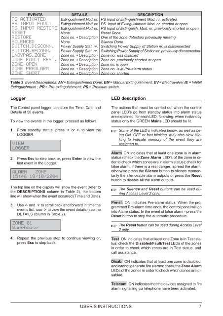
EVENTS DETAILS DESCRIPTIONPS ACTIVATED Extinguishment Mod. nr. PS Input of Extinguishment Mod. nr. activatedPS INPUT FAULT Extinguishment Mod. nr. PS Input of Extinguishment Mod. nr. shorted or openPS INPUT RESTORE Extinguishment Mod. nr. PS Input of Extinguish. Mod. nr. previously shorted or openRESET None Reset DoneRESTORE Zone no. + Description One of the zone detectors previously missingSILENCED None Silence DoneSWITCH.DISCONN. Power Supply Stat. nr. Switching Power Supply of Station nr. is disconnectedSWITCH.RECONN. Power Supply Stat. nr. Switching Power Supply of Station nr. previously disconnectedUNBYPAS.ZONE Zone no. + Description Zone no. was disabledZONE FAULT REST. Zone no. + Description Zone no. previously shorted or openZONE OPEN Zone no. + Description Zone no. is openZONE PREALARM Zone no. + Description Zone no. is in Pre-alarm statusZONE SHORT Zone no. + Description Zone no. shortedTable 2 Event Descriptions: AV= Extinguishment Done; EM = Manual Extinguishment; EV = Electrovalve; IE = InhibitExtinguishment ; PR = Pre-extinguishment; PS = Pressure switch.LoggerThe Control panel logger can store the Time, Date andDetails of 50 events.To view the events in the logger, proceed as follows.1. From standby status, press or to view theLOGGER:VIEWLOGGER2. Press Esc to step back or, press Enter to view thelast event in the Logger.ALARM ZONE15:46 18/10/2004The top line on the display will show the event (refer tothe DESCRIPTIONS column in Table 2), the bottomline will show when the event occurred (Time and Date).3. Use and to scroll back and forward in time theevents list, use to view the event details (see theDETAILS column in Table 2).ZONE 01Warehouse4. Repeat the previous step to continue viewing or,press Esc to step back.LED descriptionThe actions that must be carried out when the controlpanel LED’s go from standby status into alarm statusare explained, for each LED, following: when in standbystatus only the GREEN Mains LED should be lit.Some of the LED’s indicated below, as well as beingON, OFF or fast blinking, may also slow blinkingto indicate memory of the event they areassigned to.Alarm ON indicates that at least one zone is in alarmstatus (check the Zone Alarm LED’s of the zone in orderto check which zones are in alarm status); check forfalse alarm, if there is a real danger, spread the alarm,otherwise press the Silence button to silence momentarilythe silenceable alarm outputs or press the Resetbutton to disable all the alarm outputs.The Silence and Reset buttons can be used duringAccess Level 2 only.Pre-al. ON indicates Pre-alarm status. When the programmedPre-alarm time ends, the control panel will gointo Alarm status. In the event of false alarm - press theReset button to stop the automatic procedure.The Reset button can be used during Access Level2 only.Test ON indicates that at least one Zone is in Test status:check the Disabled/Fault/Test LEDs of the zonesin order to check which zones are in Test status, andcall assistance.Disab. ON indicates that at least one zone is disabled,and cannot generate fire alarms: check the Zone AlarmLEDs of the zones in order to check which zones are disabled.Telecom ON indicates that the devices assigned to firealarm signalling via telephone have been activated.USER’S INSTRUCTIONS 7