CONVENTIONAL FIRE PANELS - Kotesa
CONVENTIONAL FIRE PANELS - Kotesa
CONVENTIONAL FIRE PANELS - Kotesa
- No tags were found...

You also want an ePaper? Increase the reach of your titles
YUMPU automatically turns print PDFs into web optimized ePapers that Google loves.
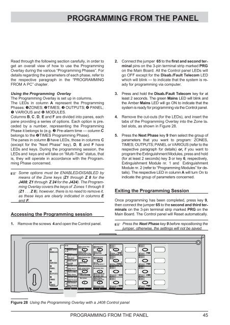
PROGRAMMING FROM THE PANELRead through the following section carefully, in order toget an overall view of how to use the ProgrammingOverlay during the various “Programming Phases”. Fordetails regarding the parameters of each phase, refer tothe respective paragraph in the “PROGRAMMINGFROM A PC” chapter.Using the Programming OverlayThe Programming Overlay is set up in columns.The LEDs in column A represent the ProgrammingPhases: ZONES; TIMES; OUTPUTS; PANEL; VARIOUS and MODULES.Columns B, C, D, E and F are divided into panes, eachpane providing a series of options. Each option is precededby a number, representing the ProgrammingPhase it belongs to (e.g. Pre-alarm time — column Cbelongs to the TIMES Programming Phase).The panes in column B have LEDs, those in columns C(except for the “Next Phase” key), D, E and F haveLEDs and keys. During the programming session, theLEDs and keys and will take on “Multi-Task” status, thatis, they will operate in accordance with the ProgrammingPhase concerned.Some options must be ENABLED/DISABLED bymeans of the Zone keys (Z1 through Z8for theJ408; Z1 through Z24for the J424). The ProgrammingOverlay covers the keys of Zones 1 through 8(Z1 ...Z8), however, there is no need to remove it,as these keys are clearly indicated in columns Eand F.Accessing the Programming session1. Remove the screws 4 and open the Control panel.2. Connect the jumper 65 to the first and second terminalpins on the 3-pin terminal strip marked PRGon the Main Board. All the Control panel LEDs willgo OFF except for the Disab./Fault Telecom LEDwhich will blink — to indicate that the system is readyfor programming via computer.3. Press and hold the Disab./Fault Telecom key for atleast 2 seconds. The green Mains LED will blink andthe Amber Mains LED will go ON to indicate that thesystem is ready for programming via the Control panel.4. Remove the cut-outs (for the LEDs), and insert thetabs of the Programming Overlay into the Zone labelslots, as shown in Figure 28.5. Press the Next Phase key 9 then select the group ofparameters that you want to program: ZONES,TIMES; OUTPUTS; PANEL or VARIOUS (refer to therespective paragraph for details) or, if you want toprogram the Extinguishment Modules, press and hold(for at least 2 seconds) key 3 or key 6, respectively,Extinguishment Module nr. 1 and ExtinguishmentModule nr. 2 (refer to “Programming Modules” for details).The respective LED in column A will turn On toindicate the group of parameters concerned.Exiting the Programming SessionOnce programming has been completed, press key 9,then connect the jumper 65 to the second and third terminalson the 3-pin terminal strip marked PRG on theMain Board. The Control panel will Reset automatically.Press the Next Phase key 9 before repositioning thejumper, otherwise, the settings will not be saved.MMM --Zone 1Zone 5Pre-alarm time Refresh time Zone 1Zone 5128 sec AlarmPre-alarmFaultAlarm verific. 1 2 3MMM MODULESUser code Day mode64 secStabilization time Reset timeExting. 1 LCD 1Power 1 Rep.1Extinguish. time Zone 1/Exting. 1Detect missingZone 5MMM --Zone 2Zone 6OC output Verification time Silence time Zone 2Zone 632 sec ResetDisablementTestSilen. Out R 4 5 6MVARIOUS MM ALARMNight mode Clock16 secConfiguration 1 Exting. 2 LCD 2Power 2 Rep.2Zone 2/Exting. 2Pre-alarm on RActivation zonesZone 6M--Zone 3Zone 7PANELMM NAC2 Alarm DL output delay Increase time Zone 3Zone 78secDouble knockTest on NACs 7 8MOUTPUTS MM DateMains off delayNAC1 Alarm Configuration 2 Increase time Expander 1 LCD 3Power 3 Rep.34secIncrease time Zone 3Zone 7Call-pointCalarmMMM Next phase Next Option Zone 4Zone 8TIMESNAC2NPre-alarmDecrease time Zone 4Zone 82secNext OutputGas detector 9 0MZONESMM NAC1NPre-alarm1secDecrease time Expander 2 LCD 4Power 4 Rep.4Decrease time Zone 4Zone 8A BCDE FFigure 28 Using the Programming Overlay with a J408 Control panelPROGRAMMING FROM THE PANEL 45