CONVENTIONAL FIRE PANELS - Kotesa
CONVENTIONAL FIRE PANELS - Kotesa
CONVENTIONAL FIRE PANELS - Kotesa
- No tags were found...

You also want an ePaper? Increase the reach of your titles
YUMPU automatically turns print PDFs into web optimized ePapers that Google loves.
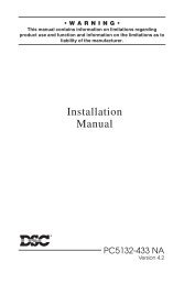
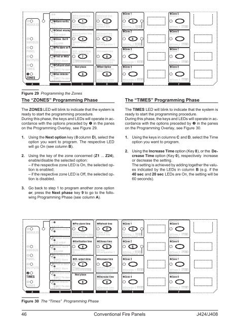
MMM 640 sec - - Zone 1Zone 5 Pre-alarm time Refresh time Zone 1Zone 5128 sec AlarmPre-alarmFaultAlarm verific. 1 2 3MMM 320 secMODULESUser code Day mode64 secStabilization time Reset timeExting. ALARM 1 LCD 1Power 1 Rep. 1Extinguish. time Zone 1/Exting. 1Zone 5Detect missingMMM 160 sec -- Zone 2Zone 6OC output Verification time Silence time Zone 2Zone 632 sec ResetDisablementTestSilen. Out R 4 5 6MMM VARIOUSALARMNight mode Clock16 secSilenceable outs Configuration 1 Exting. 2 LCD 2Power 2 Rep. 2Pre-alarm on RActivation zonesZone 2/Exting. 2Zone 6MMM - Zone 3Zone 7PANELNAC2 Alarm DL output delay Īncrease time Zone 3Zone 78 sec Double knockTest on NACs 7 8MMM OUTPUTSNAC1 Alarm DateMains off delay4 sec Configuration 2 Increase time Expander 1 LCD 3Power 3 Rep. 3Call-point alarmIncrease time Zone 3Zone 7MMM Next phase Next Option Zone 4Zone 8TIMESNAC2 Pre-alarmDecrease time Zone 4Zone 82 secNext OutputGas detector 9 0MMM 5 secZONESNAC1 Pre-alarm1 secDecrease time Expander 2 LCD 4Power 4 Rep. 4Decrease time Zone 4Zone 8A BCDE FFigure 29 Programming the ZonesThe “ZONES” Programming PhaseThe ZONES LED will blink to indicate that the system isready to start the programming procedure.During this phase, the keys and LEDs will operate in accordancewith the options preceded by in the paneson the Programming Overlay, see Figure 29.1. Using the Next option key (0 column D), select theoption you want to program. The respective LEDwill go On (see column B).2. Using the key of the zone concerned (Z1 ... Z24),enable/disable the selected option:– if the respective zone LED is On, the selected optionis enabled;– if the respective zone LED is Off, the selected optionis disabled.The “TIMES” Programming PhaseThe TIMES LED will blink to indicate that the system isready to start the programming procedure.During this phase, the keys and LEDs will operate in accordancewith the options preceded by in the paneson the Programming Overlay, see Figure 30.1. Using the keys in columns C and D, select the Timeoption you want to program.2. Using the Increase Time option (Key 8), or the DecreaseTime option (Key 0), respectively increaseor decrease the setting.The setting is achieved by adding together the valuesindicated by the LEDs in column B (e.g. if the40 sec and 20 sec LEDs are On, the setting will be60 seconds).3. Go back to step 1 to program another zone optionor, press the Next phase key 9 to go to the followingProgramming Phase (see column A).MMM 640 sec --Zone 1Zone 5Pre-alarm time Refresh time Zone 1Zone 5128 sec AlarmPre-alarmFaultAlarm verific. 1 2 3MMM 320 secMODULESUser code Day modeALARM 64 secStabilization time Reset timeExting. 1 LCD 1 Power 1 Rep. 1Extinguish. time Zone 1/Exting. 1Zone 5Detect missingMMM 160 sec --Zone 2Zone 6OC output Verification time Silence time Zone 2Zone 632 sec ResetDisablementTestSilen. Out R 4 5 6MMM VARIOUSALARMNight mode Clock16 secSilenceable outs Configuration 1 Exting. 2 LCD 2Power 2 Rep. 2Pre-alarm on RActivation zonesZone 2/Exting. 2Zone 6MMM --Zone 3Zone 7PANELNAC2 Alarm DL output delay Increase time Zone 3Zone 78 sec Double knockTest on NACs 7 8MMM OUTPUTSNAC1 Alarm DateMains off delay4 sec Configuration 2 Increase time Expander 1 LCD 3Power 3 Rep. 3Call-point alarmIncrease time Zone 3Zone 7MMM Next phase Next Option Zone 4Zone 8TIMESNAC2 Pre-alarmDecrease time Zone 4Zone 82 secNext OutputGas detector 9 0MMM 5 secZONESNAC1 Pre-alarm1 secDecrease time Expander 2 LCD 4Power 4 Rep. 4Decrease time Zone 4Zone 8A BCDE FFigure 30 The “Times” Programming Phase46 Conventional Fire Panels J424/J408