CONVENTIONAL FIRE PANELS - Kotesa
CONVENTIONAL FIRE PANELS - Kotesa
CONVENTIONAL FIRE PANELS - Kotesa
- No tags were found...

You also want an ePaper? Increase the reach of your titles
YUMPU automatically turns print PDFs into web optimized ePapers that Google loves.
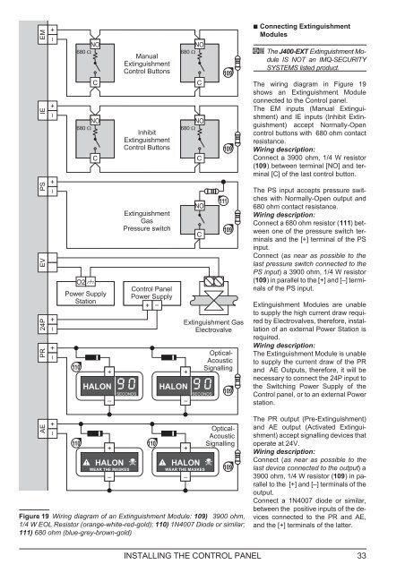
EMIENONO680 Manual680 ExtinguishmentControl ButtonsCNO680 InhibitNO680 ExtinguishmentControl ButtonsCCC109109 Connecting ExtinguishmentModulesA The J400-EXT Extinguishment ModuleIS NOT an IMQ-SECURITYSYSTEMS listed product.The wiring diagram in Figure 19shows an Extinguishment Moduleconnected to the Control panel.The EM inputs (Manual Extinguishment)and IE inputs (Inhibit Extinguishment)accept Normally-Opencontrol buttons with 680 ohm contactresistance.Wiring description:Connect a 3900 ohm, 1/4 W resistor(109) between terminal [NO] and terminal[C] of the last control button.PSEVPR 24PO2Power SupplyStation110+HALON–ExtinguishmentGasPressure switchSECONDSControl PanelPower Supply+HALON–NOCSECONDS111109Extinguishment GasElectrovalveOptical-AcousticSignalling109The PS input accepts pressure switcheswith Normally-Open output and680 ohm contact resistance.Wiring description:Connect a 680 ohm resistor (111) betweenone of the pressure switch terminalsand the [+] terminal of the PSinput.Connect (as near as possible to thelast pressure switch connected to thePS input) a 3900 ohm, 1/4 W resistor(109) in parallel to the [+] and [–] terminalsof the PS input.Extinguishment Modules are unableto supply the high current draw requiredby Electrovalves, therefore, installationof an external Power Station isrequired.Wiring description:The Extinguishment Module is unableto supply the current draw of the PRand AE Outputs, therefore, it will benecessary to connect the 24P input tothe Switching Power Supply of theControl panel, or to an external Powerstation.AE110 110+HALONWEAR THE MASKES–+HALONWEAR THE MASKES–Optical-AcousticSignallingFigure 19 Wiring diagram of an Extinguishment Module: 109) 3900 ohm,1/4 W EOL Resistor (orange-white-red-gold); 110) 1N4007 Diode or similar;111) 680 ohm (blue-grey-brown-gold)109The PR output (Pre-Extinguishment)and AE output (Activated Extinguishment)accept signalling devices thatoperate at 24V.Wiring description:Connect (as near as possible to thelast device connected to the output) a3900 ohm, 1/4 W resistor (109) inparallelto the [+] and [–] terminals of theoutput.Connect a 1N4007 diode or similar,between the positive inputs of the devicesconnected to the PR and AE,and the [+] terminals of the latter.INSTALLING THE CONTROL PANEL 33