SDR Single Duct VAV Terminals (FORM 130.13-EG1) - Enviro-Tec
SDR Single Duct VAV Terminals (FORM 130.13-EG1) - Enviro-Tec
SDR Single Duct VAV Terminals (FORM 130.13-EG1) - Enviro-Tec

Create successful ePaper yourself
Turn your PDF publications into a flip-book with our unique Google optimized e-Paper software.
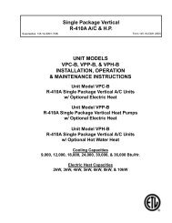
<strong>Single</strong>-<strong>Duct</strong>, <strong>VAV</strong> <strong>Terminals</strong> CATALOG: ET<strong>130.13</strong>-<strong>EG1</strong> (1212)APPLICATION AND SELECTIONHVAC systems experience 0.5” w.g. pressure drop orless in the main trunk. For systems that will have substantiallyhigher pressure variances from one zone toanother, special attention should be paid to the properselection of air terminal equipment.To date, the most common approach has been to select(size) all of the terminals based on the worst case(highest inlet static pressure) condition. Typically, thisresults in 80% (or higher) of the terminal units beingoversized for their application. This in turn results inmuch higher equipment costs, but more importantly,drastically reduced operating efficiency of each unit.This consequently decreases the ability to providecomfort control in the zone. In addition, the oversizedterminals cannot adequately control the minimum ventilationcapacity required in the heating mode.A more prudent approach is to utilize a pressure reducingdevice upstream of the terminal unit on those fewzones closest to the central fan. This device couldsimply be a manual quadrant type damper if locatedwell upstream of the terminal inlet. In tight quarters,perforated metal can be utilized as a quiet means ofreducing system pressure. This approach allows all ofthe terminal units to experience a similar (lower) inletpressure. They can be selected in a consistent mannerat lower inlet pressure conditions that will allow moreoptimally sized units.Inlet duct that is the same size as the inlet collar andas straight as possible will achieve the best acousticalperformance. For critical applications, flexible ductshould not be utilized at the terminal inlet.Zoning. On projects where internal lining of the downstreamduct is not permitted, special considerationsshould be made to obtain acceptable noise levels. Inthese cases, a greater number of smaller zones willhelp in reducing sound levels. Where possible, the firstdiffuser takeoff should be located after an elbow or teeand a greater number of small necked diffusers shouldbe utilized, rather than fewer large necked diffusers.The downstream ductwork should be carefully designedand installed to avoid noise regeneration. Bull head teearrangements should be located sufficiently downstreamof the terminal discharge to provide anestablished flow pattern downstream of the fan. Placediffusers downstream of the terminal after the airflowhas completely developed.Downstream splitter dampers can cause noise problemsif placed too close to the terminal, or whenexcessive air velocities exist. If tee arrangements areemployed, volume dampers should be used in eachbranch of the tee, and balancing dampers should beprovided at each diffuser tap. This arrangement providesmaximum flexibility in quiet balancing of thesystem.High Quality <strong>VAV</strong>Terminal withLow SoundLevelsIDEAL DUCT DESIGNSmall NeckedDiffusersDamper Located atTake-OffMinimum Required InletStatic PressureMultipleBranchTake-OffsShort Length of Non-Metallic Flexible <strong>Duct</strong>10 ENVIRO-TEC