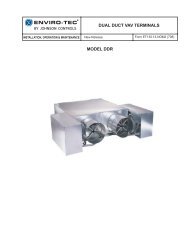
SDR Single Duct VAV Terminals (FORM 130.13-EG1) - Enviro-Tec
SDR Single Duct VAV Terminals (FORM 130.13-EG1) - Enviro-Tec
SDR Single Duct VAV Terminals (FORM 130.13-EG1) - Enviro-Tec

Create successful ePaper yourself
Turn your PDF publications into a flip-book with our unique Google optimized e-Paper software.
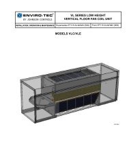
<strong>Single</strong>-<strong>Duct</strong>, <strong>VAV</strong> <strong>Terminals</strong> CATALOG: ET<strong>130.13</strong>-<strong>EG1</strong> (1212)GUIDE SPECIFICATIONSGENERALFurnish and install <strong>Enviro</strong>-<strong>Tec</strong>® Model <strong>SDR</strong> <strong>Single</strong> <strong>Duct</strong>Variable Air Volume Terminal Units of the sizes andcapacities as scheduled. <strong>Terminals</strong> shall be certifiedby AHRI and bear the AHRI 880 seal.CONSTRUCTION<strong>Terminals</strong> shall be constructed of not less than 22gauge galvanized steel, able to withstand a 125 hoursalt spray test per ASTM B-117. Stainless steel casings,or galvannealed steel casings with a bakedenamel paint finish, may be used as an alternative.The terminal casing shall be mechanically assembled(spot-welded casings are not acceptable).Casing shall be internally lined with 1/2” thick fiberglassinsulation, rated for a maximum air velocity of 5000f.p.m. Maximum thermal conductivity shall be .24 (BTU• in) / (hr • ft 2 • °F). Insulation must meet all requirementsof ASTM C1071 (including C665), UL 181 forerosion, and carry a 25/50 rating for flame spread/smoke developed per ASTM E-84, UL 723 and NFPA90A. Raw insulation edges on the discharge of the unitmust be covered with metal liner to eliminate flaking ofinsulation during field duct connections. Simple “buttering”of raw edges with an approved sealant is notacceptable.All appurtenances including control assemblies, controlenclosures, hot water heating coils, and electric heatingcoils shall not extend beyond the top and bottom of theunit casing. At an inlet velocity of 2000 f.p.m., thestatic pressure drop across the basic terminal or basicterminal with a sound attenuator shall not exceed .08”W.G. for all unit sizes.PRIMARY AIR VALVEThe primary air valve shall consist of a minimum 22gauge cylindrical body that includes embossment ringsfor rigidity. The damper blade shall be connected to asolid shaft by means of an integral molded sleeve whichdoes not require screw or bolt fasteners. The shaftshall be manufactured of a low thermal conductingcomposite material, and include a molded damper positionindicator visible from the exterior of the unit. Thedamper shall pivot in self lubricating bearings. Thedamper actuator shall be mounted on the exterior ofthe terminal for ease of service. The valve assemblyshall include internal mechanical stops for both fullopen and closed positions. The damper blade seal shallbe secured without use of adhesives. The air valveleakage shall not exceed 1% of maximum inlet ratedairflow at 3” W.G. inlet pressure.PRIMARY AIRFLOW SENSORFor inlet diameters 6” or greater, the differential pressureairflow sensor shall traverse the duct along twoperpendicular diameters. Cylindrically shaped inletsshall utilize the equal cross sectional area or log-lineartraverse method. <strong>Single</strong> axis sensor shall not beacceptable for duct diameters 6” or larger. A minimumof 12 total pressure sensing points shall be utilized.The total pressure inputs shall be averaged using apressure chamber located at the center of the sensor.A sensor that delivers the differential pressure signalfrom one end of the sensor is not acceptable. Thesensor shall output an amplified differential pressuresignal that is at least 2.5 times the equivalent velocitypressure signal obtained from a conventional pitot tube.The sensor shall develop a differential pressure of 0.03”w.g. at an air velocity of < 450 FPM. Documentationshall be submitted which substantiates this requirement.Balancing taps and airflow calibration chartsshall be provided for field airflow measurements.HOT WATER COIL<strong>Single</strong> duct terminal shall include an integral hot watercoil where indicated on the plans. The coil shall bemanufactured by the terminal unit manufacturer andshall have a minimum 22 gauge galvanized sheet metalcasing. Stainless steel casings, or galvannealed steelcasings with a baked enamel paint finish, may be usedas an alternative. Coil to be constructed of pure aluminumfins with full fin collars maintaining accurate finspacing and maximum tube contact. Fins shall bespaced with a minimum of 10 per inch and mechanicallyfixed to seamless copper tubes for maximum heattransfer.Each coil shall be hydrostatically tested at a minimumof 450 PSIG under water, and rated for a maximum300 PSIG working pressure at 200°F.ELECTRIC HEATERSTerminal shall include an integral electric heater whereindicated on the plans. Heater shall be cETL listed.The heater cabinet shall be constructed of not less than20 gauge galvanized steel. Stainless steel cabinets,or galvannealed steel casings with a baked enamelpaint finish, may be used as an alternative. Heatershall have a hinged access panel for entry to the controls.Electric heaters shall be factory mounted to the terminalwith the heating elements located upstream of theairflow control damper to ensure uniform velocityprofile over the elements. Elements located downstreamof the damper are not acceptable.26 ENVIRO-TEC