EVA Series Installation Operation and Maintenance Manual
EVA Series Installation Operation and Maintenance Manual
EVA Series Installation Operation and Maintenance Manual

Create successful ePaper yourself
Turn your PDF publications into a flip-book with our unique Google optimized e-Paper software.
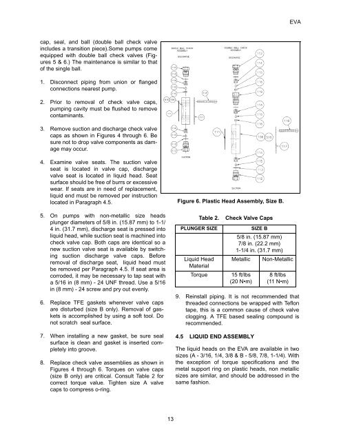
<strong>EVA</strong>cap, seal, <strong>and</strong> ball (double ball check valveincludes a transition piece).Some pumps comeequipped with double ball check valves (Figures5 & 6.) The maintenance is similar to thatof the single ball.1. Disconnect piping from union or flangedconnections nearest pump.2. Prior to removal of check valve caps,pumping cavity must be flushed to removecontaminants.3. Remove suction <strong>and</strong> discharge check valvecaps as shown in Figures 4 through 6. Besure not to drop valve components as damagemay occur.4. Examine valve seats. The suction valveseat is located in valve cap, dischargevalve seat is located in liquid head. Seatsurface should be free of burrs or excessivewear. If seats are in need of replacement,liquid end must be removed per instructionlocated in Paragraph 4.5.5. On pumps with non-metallic size headsplunger diameters of 5/8 in. (15.87 mm) to 1-1/4 in. (31.7 mm), discharge seat is pressed intoliquid head, while suction seat is machined intocheck valve cap. Both caps are identical so anew suction valve seat is available by switchingsuction discharge valve caps. Beforeremoval of discharge seat, liquid head mustbe removed per Paragraph 4.5. If seat area iscorroded, it may be necessary to tap seat witha 5/16 in (8 mm) - 24 UNF thread. Use a 5/16in (8 mm) - 24 screw <strong>and</strong> pry out evenly.6. Replace TFE gaskets whenever valve capsare disturbed (size B only). Removal of gasketsis accomplished by using a soft tool. Donot scratch seal surface.7. When installing a new gasket, be sure sealsurface is clean <strong>and</strong> gasket is inserted completelyinto groove.8. Replace check valve assemblies as shown inFigures 4 through 6. Torques on valve caps(size B only) are critical. Consult Table 2 forcorrect torque value. Tighten size A valvecaps to compress o-ring.Figure 6. Plastic Head Assembly, Size B.Table 2.PLUNGER SIZELiquid HeadMaterialTorqueCheck Valve Caps9. Reinstall piping. It is not recommended thatthreaded connections be wrapped with Teflontape, this is a common cause of check valveclogging. A TFE based sealing compound isrecommended.4.5 LIQUID END ASSEMBLYSIZE B5/8 in. (15.87 mm)7/8 in. (22.2 mm)1-1/4 in. (31.7 mm)Metallic15 ft/lbs(20 N•m)Non-Metallic8 ft/lbs(11 N•m)The liquid heads on the <strong>EVA</strong> are available in twosizes (A - 3/16, 1/4, 3/8 & B - 5/8, 7/8, 1-1/4). Withthe exception of torque specifications <strong>and</strong> themetal support ring on plastic heads, non metallicsizes are similar, <strong>and</strong> should be addressed in thesame fashion.13