EVA Series Installation Operation and Maintenance Manual
EVA Series Installation Operation and Maintenance Manual
EVA Series Installation Operation and Maintenance Manual

You also want an ePaper? Increase the reach of your titles
YUMPU automatically turns print PDFs into web optimized ePapers that Google loves.
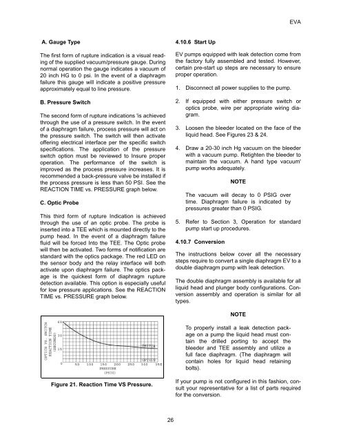
<strong>EVA</strong>A. Gauge TypeThe first form of rupture indication is a visual readingof the supplied vacuum/pressure gauge. Duringnormal operation the gauge indicates a vacuum of20 inch HG to 0 psi. In the event of a diaphragmfailure this gauge will indicate a positive pressureapproximately equal to line pressure.B. Pressure SwitchThe second form of rupture indications 'is achievedthrough the use of a pressure switch. In the eventof a diaphragm failure, process pressure will act onthe pressure switch. The switch will then activateoffering electrical interface per the specific switchspecifications. The application of the pressureswitch option must be reviewed to Insure properoperation. The performance of the switch isimproved as the process pressure increases. It isrecommended a back-pressure valve be installed ifthe process pressure is less than 50 PSI. See theREACTION TIME vs. PRESSURE graph below.C. Optic ProbeThis third form of rupture Indication is achievedthrough the use of an optic probe. The probe isinserted into a TEE which is mounted directly to thepump head. In the event of a diaphragm failurefluid will be forced Into the TEE. The Optic probewill then be activated. Two forms of notification arest<strong>and</strong>ard with the optics package. The red LED onthe sensor body <strong>and</strong> the relay interface will bothactivate upon diaphragm failure. The optics packageis the quickest form of diaphragm rupturedetection available. This option is especially usefulfor low pressure applications. See the REACTIONTIME vs. PRESSURE graph below.4.10.6 Start UpEV pumps equipped with leak detection come fromthe factory fully assembled <strong>and</strong> tested. However,certain pre-start up steps are necessary to ensureproper operation.1. Disconnect all power supplies to the pump.2. If equipped with either pressure switch oroptics probe, wire per appropriate wiring diagram.3. Loosen the bleeder located on the face of theliquid head. See Figures 23 & 24.4. Draw a 20-30 inch Hg vacuum on the bleederwith a vacuum pump. Retighten the bleeder tomaintain the vacuum. A h<strong>and</strong> type vacuum'pump works adequately.NOTEThe vacuum will decay to 0 PSIG overtime. Diaphragm failure is indicated bypressures greater than 0 PSIG.5. Refer to Section 3, <strong>Operation</strong> for st<strong>and</strong>ardpump start up procedures.4.10.7 ConversionThe instructions below cover all the necessarysteps require to convert a single diaphragm EV to adouble diaphragm pump with Ieak detection.The double diaphragm assembly is available for allliquid head <strong>and</strong> plunger body configurations. Conversionassembly <strong>and</strong> operation is similar for alltypes.NOTETo properly install a leak detection packageon a pump the liquid head must containthe drilled porting to accept thebleeder <strong>and</strong> TEE assembly <strong>and</strong> utilize afull face diaphragm. (The diaphragm willcontain holes for liquid head retainingbolts).Figure 21. Reaction Time VS Pressure.If your pump is not configured in this fashion, consultyour representative for a list of parts requiredfor the conversion.26