EVA Series Installation Operation and Maintenance Manual
EVA Series Installation Operation and Maintenance Manual
EVA Series Installation Operation and Maintenance Manual

Create successful ePaper yourself
Turn your PDF publications into a flip-book with our unique Google optimized e-Paper software.
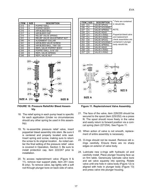
<strong>EVA</strong>ITEM SIZE DESCRIPTION214 A POPPET BALL215 A POPPET BODY216 A AIR BLEED BALL217 A AIR BLEED CAP219 A RELIEF VALVE SPRING221 A RELIEF VALVE ADJUSTMENT NUT240 B ALIGNMENT COLLAR241 B AIR BLEED VALVE SCREW242 B AIR BLEED BALL, 7/64” OD243 B REPL VALVE POPPET BODY244 B POPPET BALL, 5/16” OD245 B REPL VALVE SPRING246 B REPL VALVE NUTITEM SIZE DESCRIPTION225 A VALVE SPOOL226 A VALVE HOUSING227 A VALVE SPRING228 A VALVE HEAD229* A VALVE 0-RING230* A VALVE 0-RING252 B VALVE SPOOL253 B VALVE HOUSING254 B VALVE SPRING255 B VALVE HEAD256* B VALVE 0-RING257* B VALVE 0-RING* Parts are containedin rebuild kits.NOTE:Poppet/air bleed valve<strong>and</strong> replacementcheck assemblies arecontained in plungerbody rebuild kits.SIZE ASIZE BSIZE AFIGURE 10. Pressure Relief/Air Bleed Assembly.18. The relief spring in each pump head is specificfor each application (Under no circumstancesshould any other spring be used in this assembly).19. To re-assemble pressure relief valve, insertpoppet/air bleed assembly into stem. Be sure itis centered <strong>and</strong> properly located onto seat.Insert spring <strong>and</strong> screw, making sure to returnthe screw to its original location. As noted earlierthe final setting of the pressure relief valveis covered in <strong>Operation</strong>, Section 3. Be sure toinstall protection cap, item 222/247 prior toinstallation.20. To access replenishment valve (Figure 9 &11), remove rear support plate, item 251 (sizeB only). To remove valve, tap lightly with a softrod through plunger bore on back side of valve.Figure 11. Replenishment Valve Assembly.21. The face of the valve, item 228/255 should besecured to the spool (item 225/252) via a pressfit. The spool should move freely in the valve<strong>and</strong> easily return to forward position via a conicalspring (item 227/254). See Figure 11.22. When action of valve is not smooth, replacementof entire assembly is necessary.23. O-rings should not be reused. Remove old o-rings carefully. Ensure there are no sharpedges on exterior of valve body.24. Lubricate new o-rings with hydraulic oil <strong>and</strong>carefully install. Place plunger housing face upon firm table. Generously lubricate valve bore<strong>and</strong> set valve squarely into opening. Rotatevalve until one hole in valve body (Figure 12) isaligned with hole in plunger body (Figure 13)<strong>and</strong> press valve into plunger housing.17