EVA Series Installation Operation and Maintenance Manual
EVA Series Installation Operation and Maintenance Manual
EVA Series Installation Operation and Maintenance Manual

Create successful ePaper yourself
Turn your PDF publications into a flip-book with our unique Google optimized e-Paper software.
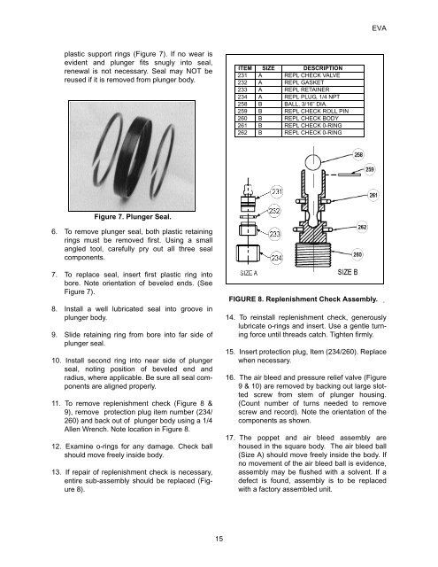
<strong>EVA</strong>plastic support rings (Figure 7). If no wear isevident <strong>and</strong> plunger fits snugly into seal,renewal is not necessary. Seal may NOT bereused if it is removed from plunger body.ITEM SIZE DESCRIPTION231 A REPL CHECK VALVE232 A REPL GASKET233 A REPL RETAINER234 A REPL PLUG, 1/4 NPT258 B BALL, 3/16” DIA.259 B REPL CHECK ROLL PIN260 B REPL CHECK BODY261 B REPL CHECK 0-RING262 B REPL CHECK 0-RINGFigure 7. Plunger Seal.6. To remove plunger seal, both plastic retainingrings must be removed first. Using a smallangled tool, carefully pry out all three sealcomponents.7. To replace seal, insert first plastic ring intobore. Note orientation of beveled ends. (SeeFigure 7).8. Install a well lubricated seal into groove inplunger body.9. Slide retaining ring from bore into far side ofplunger seal.10. Install second ring into near side of plungerseal, noting position of beveled end <strong>and</strong>radius, where applicable. Be sure all seal componentsare aligned properly.11. To remove replenishment check (Figure 8 &9), remove protection plug item number (234/260) <strong>and</strong> back out of plunger body using a 1/4Allen Wrench. Note location in Figure 8.12. Examine o-rings for any damage. Check ballshould move freely inside body.13. If repair of replenishment check is necessary,entire sub-assembly should be replaced (Figure8).FIGURE 8. Replenishment Check Assembly.14. To reinstall replenishment check, generouslylubricate o-rings <strong>and</strong> insert. Use a gentle turningforce until threads catch. Tighten firmly.15. Insert protection plug, Item (234/260). Replacewhen necessary.16. The air bleed <strong>and</strong> pressure relief valve (Figure9 & 10) are removed by backing out large slottedscrew from stem of plunger housing.(Count number of turns needed to removescrew <strong>and</strong> record). Note the orientation of thecomponents as shown.17. The poppet <strong>and</strong> air bleed assembly arehoused in the square body. The air bleed ball(Size A) should move freely inside the body. Ifno movement of the air bleed ball is evidence,assembly may be flushed with a solvent. If adefect is found, assembly is to be replacedwith a factory assembled unit..15