Sierra Series 830/840/860 Side-Trak™ and ... - Sierra Instruments
Sierra Series 830/840/860 Side-Trak™ and ... - Sierra Instruments
Sierra Series 830/840/860 Side-Trak™ and ... - Sierra Instruments

Create successful ePaper yourself
Turn your PDF publications into a flip-book with our unique Google optimized e-Paper software.
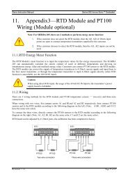
<strong>Series</strong> <strong>830</strong>/<strong>840</strong>/<strong>860</strong> Instruction ManualChapter 2 InstallationWiring Transducers with 15-Pin D-ConnectorsInput Power Connections+15VCase910111213141512345678+COM+15/0/-15VdcPowerSupply-15VPin 3 connection forcontrollers onlyFigured 2-9. Input Power (15-Pin D-Connector)Note: Use separate, dedicated wires for pins 9 <strong>and</strong> 10 to the power supply commonon meters <strong>and</strong> pins 9,10 <strong>and</strong> 3 on controllers.Output Signal ConnectionsSt<strong>and</strong>ard output for all transducers is a 0-5 V DC signal, which directlycorresponds to the0 to 100% mass flow full scale range.Output signals are linear <strong>and</strong> require a minimum load resistance of1000 Ohms (4-20 mA output600 Ohms maximum loop resistance).Notes:Figure 2-10. Output Signal (15-Pin D-Connector)1. Panel meter or read-out device should be wired to beat thesame ground potential as the power supply.2. 4-20 mA output signal is ground referenced (“non-isolated”).Warning: Do not apply any external voltage to this loop.IM-83/84/86-H 2-11