Installation Instructions - Clipsal
Installation Instructions - Clipsal
Installation Instructions - Clipsal

Create successful ePaper yourself
Turn your PDF publications into a flip-book with our unique Google optimized e-Paper software.
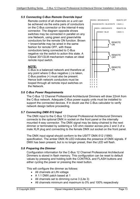
Intelligent Building SeriesC-Bus 12 Channel Professional Architectural Dimmer <strong>Installation</strong> <strong>Instructions</strong>5.5 Connecting C-Bus Remote Override InputRemote control of all channels on a unit canbe achieved via the extra pairs of conductorson the C-Bus connector or the internal 4-wayconnector. The diagram opposite showsswitches may be connected in parallel on anyone Network, using green and green/whiteconductors for the remote ON function. Brown+ brown/white may be wired in the samefashion for remote OFF, with theseconductors being connected to C-Busnegative via the switch to action this state. A<strong>Clipsal</strong> 30/1/2LM mechanism makes an idealremote input switch.NOTE:C-Bus is a balanced network and therefore atany point where C-Bus negative (-) is taken,C-Bus positive (+) must also be present.Hence both network conductors must belooped through all remote input switches onthe Network.5.6 C-Bus Power RequirementsThe C-Bus 12 Channel Professional Architectural Dimmers will draw 22mA fromthe C-Bus network. Adequate C-Bus power supply units must be installed tosupport the connected devices. If in doubt use the C-Bus calculator to verifynetwork design before proceeding.5.7 Connecting DMX-512 InputThe DMX input to the C-Bus 12 Channel Professional Architectural Dimmersconnects to the optional DMX in socket on the front panel or the internallymounted 4-way connector. The DMX signal may be daisy-chained to the nextdimmer or terminated by soldering a 120 ohm resistor across pins 2 and 3 of amale XLR plug and connecting to the female DMX out socket on the front panel.The DMX input signal should conform to the USITT DMX-512 (1990)specification. The amber DMX IN LED indicates the presence of DMX signals. IfDMX has been present, but is no longer preset, then the LED will flash.5.8 Preparing the DimmerConfiguration information for the C-Bus 12 Channel Professional ArchitecturalDimmers is stored in flash memory. This configuration can be reset to defaultvalues by pressing and holding both the CONTROL and FLASH buttons andeither cycling the power or pressing the reset button.This will configure the dimmer as follows:• All channels at LIN voltage• A 1:1 DMX patch based at 1• All channels set to dimming curve 3 (Lite 3)• All channels minimum and maximum to 0% and 100% respectively© Copyright 2003 <strong>Clipsal</strong> Integrated Systems Pty Ltd. Page 13