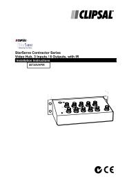
Installation Instructions - Clipsal
Installation Instructions - Clipsal
Installation Instructions - Clipsal

Create successful ePaper yourself
Turn your PDF publications into a flip-book with our unique Google optimized e-Paper software.
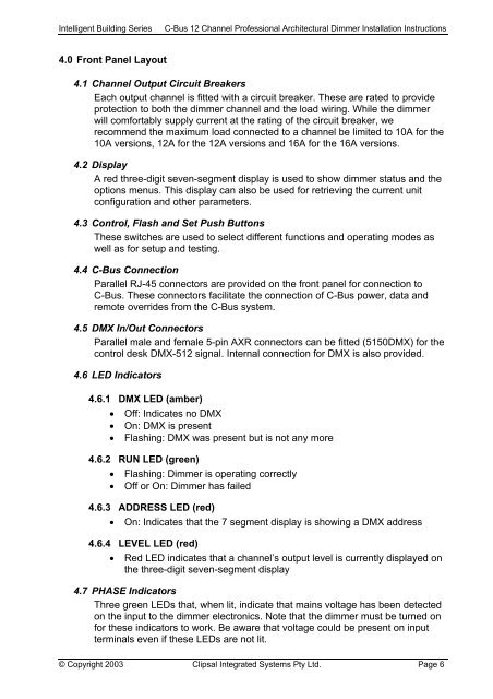
Intelligent Building SeriesC-Bus 12 Channel Professional Architectural Dimmer <strong>Installation</strong> <strong>Instructions</strong>4.0 Front Panel Layout4.1 Channel Output Circuit BreakersEach output channel is fitted with a circuit breaker. These are rated to provideprotection to both the dimmer channel and the load wiring. While the dimmerwill comfortably supply current at the rating of the circuit breaker, werecommend the maximum load connected to a channel be limited to 10A for the10A versions, 12A for the 12A versions and 16A for the 16A versions.4.2 DisplayA red three-digit seven-segment display is used to show dimmer status and theoptions menus. This display can also be used for retrieving the current unitconfiguration and other parameters.4.3 Control, Flash and Set Push ButtonsThese switches are used to select different functions and operating modes aswell as for setup and testing.4.4 C-Bus ConnectionParallel RJ-45 connectors are provided on the front panel for connection toC-Bus. These connectors facilitate the connection of C-Bus power, data andremote overrides from the C-Bus system.4.5 DMX In/Out ConnectorsParallel male and female 5-pin AXR connectors can be fitted (5150DMX) for thecontrol desk DMX-512 signal. Internal connection for DMX is also provided.4.6 LED Indicators4.6.1 DMX LED (amber)• Off: Indicates no DMX• On: DMX is present• Flashing: DMX was present but is not any more4.6.2 RUN LED (green)• Flashing: Dimmer is operating correctly• Off or On: Dimmer has failed4.6.3 ADDRESS LED (red)• On: Indicates that the 7 segment display is showing a DMX address4.6.4 LEVEL LED (red)• Red LED indicates that a channel’s output level is currently displayed onthe three-digit seven-segment display4.7 PHASE IndicatorsThree green LEDs that, when lit, indicate that mains voltage has been detectedon the input to the dimmer electronics. Note that the dimmer must be turned onfor these indicators to work. Be aware that voltage could be present on inputterminals even if these LEDs are not lit.© Copyright 2003 <strong>Clipsal</strong> Integrated Systems Pty Ltd. Page 6