Installation Instructions - Clipsal
Installation Instructions - Clipsal
Installation Instructions - Clipsal

You also want an ePaper? Increase the reach of your titles
YUMPU automatically turns print PDFs into web optimized ePapers that Google loves.
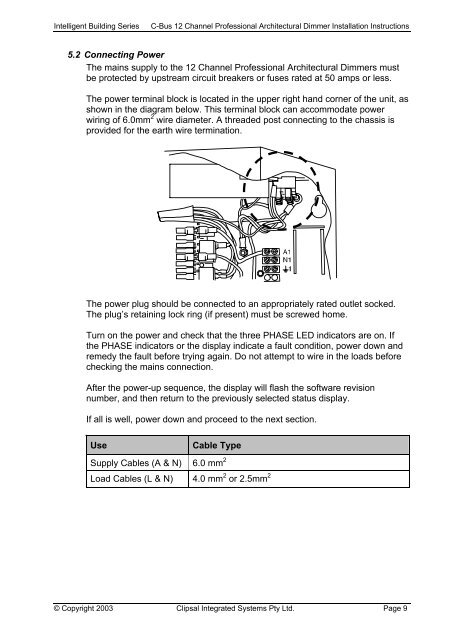
Intelligent Building SeriesC-Bus 12 Channel Professional Architectural Dimmer <strong>Installation</strong> <strong>Instructions</strong>5.2 Connecting PowerThe mains supply to the 12 Channel Professional Architectural Dimmers mustbe protected by upstream circuit breakers or fuses rated at 50 amps or less.The power terminal block is located in the upper right hand corner of the unit, asshown in the diagram below. This terminal block can accommodate powerwiring of 6.0mm 2 wire diameter. A threaded post connecting to the chassis isprovided for the earth wire termination.The power plug should be connected to an appropriately rated outlet socked.The plug’s retaining lock ring (if present) must be screwed home.Turn on the power and check that the three PHASE LED indicators are on. Ifthe PHASE indicators or the display indicate a fault condition, power down andremedy the fault before trying again. Do not attempt to wire in the loads beforechecking the mains connection.After the power-up sequence, the display will flash the software revisionnumber, and then return to the previously selected status display.If all is well, power down and proceed to the next section.UseCable TypeSupply Cables (A & N) 6.0 mm 2Load Cables (L & N) 4.0 mm 2 or 2.5mm 2© Copyright 2003 <strong>Clipsal</strong> Integrated Systems Pty Ltd. Page 9