
Create successful ePaper yourself
Turn your PDF publications into a flip-book with our unique Google optimized e-Paper software.
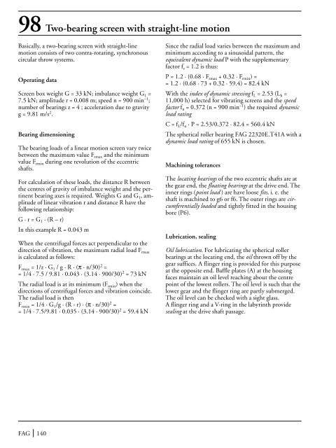
98 Two-bearing screen with straight-line motionBasically, a two-bearing screen with straight-linemotion consists <strong>of</strong> two contra-rotating, synchronouscircular throw systems.Operating dataScreen box weight G = 33 kN; imbalance weight G 1 =7.5 kN; amplitude r = 0.008 m; speed n = 900 min –1 ;number <strong>of</strong> bearings z = 4 ; acceleration due to gravityg = 9.81 m/s 2 .<strong>Bearing</strong> dimensioning<strong>The</strong> bearing loads <strong>of</strong> a linear motion screen vary twicebetween the maximum value F rmax and the minimumvalue F rmin during one revolution <strong>of</strong> the eccentricshafts.For calculation <strong>of</strong> these loads, the distance R betweenthe centres <strong>of</strong> gravity <strong>of</strong> imbalance weight and the pertinentbearing axes is required. Weights G and G 1 , amplitude<strong>of</strong> linear vibration r and distance R have thefollowing relationship:G · r = G 1 · (R – r)In this example R = 0.043 mWhen the centrifugal forces act perpendicular to thedirection <strong>of</strong> vibration, the maximum radial load F rmaxis calculated as follows:F rmax = 1/z · G 1 / g · R · (π · n/30) 2 == 1/4 · 7.5 / 9.81 · 0.043 · (3.14 · 900/30) 2 = 73 kN<strong>The</strong> radial load is at its minimum (F rmin ) when thedirections <strong>of</strong> centrifugal forces and vibration coincide.<strong>The</strong> radial load is thenF rmin = 1/4 · G 1 /g · (R - r) · (π · n/30) 2 == 1/4 · 7.5/9.81 · 0.035 · (3.14 · 900/30) 2 = 59.4 kNSince the radial load varies between the maximum andminimum according to a sinusoidal pattern, theequivalent dynamic load P with the supplementaryfactor f z = 1.2 is thus:P = 1.2 · (0.68 · F rmax + 0.32 · F rmin ) == 1.2 · (0.68 · 73 + 0.32 · 59.4) = 82.4 kNWith the index <strong>of</strong> dynamic stressing f L = 2.53 (L h =11,000 h) selected for vibrating screens and the speedfactor f n = 0.372 (n = 900 min –1 ) the required dynamicload ratingC = f L /f n · P = 2.53/0.372 · 82.4 = 560.4 kN<strong>The</strong> spherical roller bearing FAG 22320E.T41A with adynamic load rating <strong>of</strong> 655 kN is chosen.Machining tolerances<strong>The</strong> locating bearings <strong>of</strong> the two eccentric shafts are atthe gear end, the floating bearings at the drive end. <strong>The</strong>inner rings (point load ) are have loose fits, i. e. theshaft is machined to g6 or f6. <strong>The</strong> outer rings are circumferentiallyloaded and tightly fitted in the housingbore (P6).Lubrication, sealingOil lubrication. For lubricating the spherical rollerbearings at the locating end, the oil thrown <strong>of</strong>f by thegear suffices. A flinger ring is provided for this purposeat the opposite end. Baffle plates (A) at the housingfaces maintain an oil level reaching about the centrepoint <strong>of</strong> the lowest rollers. <strong>The</strong> oil level is such that thelower gear and the flinger ring are partly submerged.<strong>The</strong> oil level can be checked with a sight glass.A flinger ring and a V-ring in the labyrinth providesealing at the drive shaft passage.FAG 140