
You also want an ePaper? Increase the reach of your titles
YUMPU automatically turns print PDFs into web optimized ePapers that Google loves.
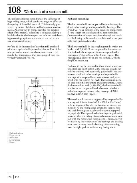
108 Work rolls <strong>of</strong> a section mill<strong>The</strong> roll stand frames expand under the influence <strong>of</strong>high rolling loads, which can have a negative effect onthe quality <strong>of</strong> the rolled material. This is usually preventedby means <strong>of</strong> elaborate roll adjustment mechanisms.Another way to compensate for the negativeeffect <strong>of</strong> the material's elasticity is to hydraulically preloadthe chocks which support the rolls and their bearingmountings against each other via the roll stands(see schematic drawing).9 <strong>of</strong> the 13 in-line stands <strong>of</strong> a section mill are fittedwith such hydraulically preloaded chocks. Five <strong>of</strong> thenine preloaded stands can also operate as universalstands. For this purpose they are equipped with twovertically arranged roll sets.Roll neck mountings<strong>The</strong> horizontal rolls are supported by multi-row cylindricalroller bearings and tapered roller bearings. <strong>The</strong>cylindrical roller bearings at the drive end compensatefor the length variations caused by heat expansion.Compensation <strong>of</strong> length variations through the chockaxially floating in the stand at the drive end is not possiblewith preloaded chocks.<strong>The</strong> horizontal rolls in the roughing stands, which areloaded with 3,150 kN, are supported in four-row cylindricalroller bearings and four-row tapered rollerbearings <strong>of</strong> 355.6 x 257.2 x 323.8 mm (fig. a). <strong>The</strong>bearings have a loose fit on the roll neck (e7), whichsimplifies mounting.No loose fit can be provided in those stands where sectionsteels are finish-rolled as the required quality canonly be achieved with accurately guided rolls. For thisreason cylindrical roller bearings and tapered rollerbearings with a tapered bore were selected and pressfittedonto the tapered roll neck. <strong>The</strong> hydraulic methodused simplifies mounting and dismounting. Due tothe lower rolling load (2,550 kN), the horizontal rollsin this case are supported by double-row cylindricalroller bearings and tapered roller bearings <strong>of</strong> 220.1x 336.6 x 244.5 mm (fig. b).<strong>The</strong> vertical rolls are each supported by a tapered rollerbearing pair (dimensions 165.1 x 336.6 x 194.2 mm)in O arrangement (fig. a). <strong>The</strong> bearings sit directly onthe rolls. As the rolling stock enters, the vertical rollsand their bearings are accelerated to operating speedvery quickly. <strong>The</strong> tapered roller bearings are preloadedto ensure that the rolling elements always maintain contactwith the raceways at these speeds. This is achievedby matching the tolerances <strong>of</strong> the bearings and bearingseats in such a way that the bearings after mountinghave the right preload without any fitting work.1 Hydraulic piston2 Upper chock3 Piston ram4 Lower chock5 FrameFAG 152