roof framing connections in conventional residential construction
roof framing connections in conventional residential construction
roof framing connections in conventional residential construction

You also want an ePaper? Increase the reach of your titles
YUMPU automatically turns print PDFs into web optimized ePapers that Google loves.
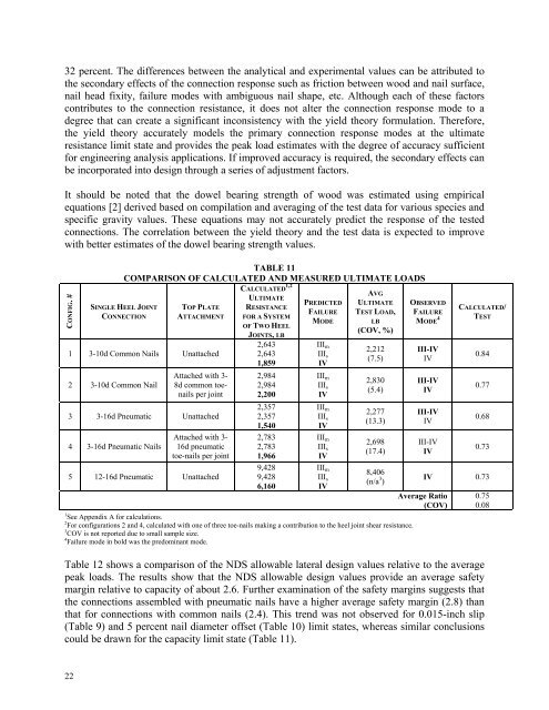
32 percent. The differences between the analytical and experimental values can be attributed tothe secondary effects of the connection response such as friction between wood and nail surface,nail head fixity, failure modes with ambiguous nail shape, etc. Although each of these factorscontributes to the connection resistance, it does not alter the connection response mode to adegree that can create a significant <strong>in</strong>consistency with the yield theory formulation. Therefore,the yield theory accurately models the primary connection response modes at the ultimateresistance limit state and provides the peak load estimates with the degree of accuracy sufficientfor eng<strong>in</strong>eer<strong>in</strong>g analysis applications. If improved accuracy is required, the secondary effects canbe <strong>in</strong>corporated <strong>in</strong>to design through a series of adjustment factors.It should be noted that the dowel bear<strong>in</strong>g strength of wood was estimated us<strong>in</strong>g empiricalequations [2] derived based on compilation and averag<strong>in</strong>g of the test data for various species andspecific gravity values. These equations may not accurately predict the response of the tested<strong>connections</strong>. The correlation between the yield theory and the test data is expected to improvewith better estimates of the dowel bear<strong>in</strong>g strength values.CONFIG. #TABLE 11COMPARISON OF CALCULATED AND MEASURED ULTIMATE LOADSSINGLE HEEL JOINTCONNECTIONTOP PLATEATTACHMENT1 3-10d Common Nails Unattached2 3-10d Common NailAttached with 3-8d common toenailsper jo<strong>in</strong>t3 3-16d Pneumatic Unattached4 3-16d Pneumatic NailsAttached with 3-16d pneumatictoe-nails per jo<strong>in</strong>t5 12-16d Pneumatic UnattachedCALCULATED 1,2ULTIMATERESISTANCEFOR A SYSTEMOF TWO HEELJOINTS, LB2,6432,6431,8592,9842,9842,2002,3572,3571,5402,7832,7831,9669,4289,4286,160PREDICTEDFAILUREMODEIII mIII sIVIII mIII sIVIII mIII sIVIII mIII sIVIII mIII sIVAVGULTIMATETEST LOAD,LB(COV, %)2,212(7.5)2,830(5.4)2,277(13.3)2,698(17.4)8,406(n/a 3 )1 See Appendix A for calculations.2 For configurations 2 and 4, calculated with one of three toe-nails mak<strong>in</strong>g a contribution to the heel jo<strong>in</strong>t shear resistance.3 COV is not reported due to small sample size.4 Failure mode <strong>in</strong> bold was the predom<strong>in</strong>ant mode.OBSERVEDFAILUREMODE 4III-IVIVIII-IVIVIII-IVIVIII-IVIVAverage Ratio(COV)CALCULATED/TEST0.840.770.680.73IV 0.730.750.08Table 12 shows a comparison of the NDS allowable lateral design values relative to the averagepeak loads. The results show that the NDS allowable design values provide an average safetymarg<strong>in</strong> relative to capacity of about 2.6. Further exam<strong>in</strong>ation of the safety marg<strong>in</strong>s suggests thatthe <strong>connections</strong> assembled with pneumatic nails have a higher average safety marg<strong>in</strong> (2.8) thanthat for <strong>connections</strong> with common nails (2.4). This trend was not observed for 0.015-<strong>in</strong>ch slip(Table 9) and 5 percent nail diameter offset (Table 10) limit states, whereas similar conclusionscould be drawn for the capacity limit state (Table 11).22