roof framing connections in conventional residential construction
roof framing connections in conventional residential construction
roof framing connections in conventional residential construction

Create successful ePaper yourself
Turn your PDF publications into a flip-book with our unique Google optimized e-Paper software.
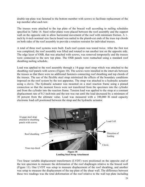
double top plate was fastened to the bottom member with screws to facilitate replacement of thetop member after each test.The trusses were attached to the top plate of the braced wall accord<strong>in</strong>g to nail<strong>in</strong>g schedulesspecified <strong>in</strong> Table 14. Steel roller plates were placed between the <strong>roof</strong> assembly and the supportwall on the opposite side to allow horizontal movement of the <strong>roof</strong> with m<strong>in</strong>imum friction. A 1-<strong>in</strong>ch by 6-<strong>in</strong>ch nom<strong>in</strong>al size fascia board was nailed to the plumb-cut ends of the truss top chordson both sides of the <strong>roof</strong> assembly to provide a rotation restra<strong>in</strong>t for <strong>in</strong>dividual trusses.A total of three <strong>roof</strong> systems were built. Each <strong>roof</strong> system was tested twice. After the first testwas completed, the <strong>roof</strong> assembly was lifted and rotated to run another test on the opposite side.The edge layer of OSB, that was attached with screws, was removed temporarily and the trusseswere connected to the new top plate. The OSB panels were reattached us<strong>in</strong>g a standard <strong>roof</strong>sheath<strong>in</strong>g nail<strong>in</strong>g schedule.Load was applied to the <strong>roof</strong> assembly through a 14-gage steel strap which was attached to thesheath<strong>in</strong>g <strong>roof</strong> panels with screws (Figure 10). The screws were <strong>in</strong>stalled <strong>in</strong> the <strong>in</strong>tervals betweenthe trusses so that there were no additional fasteners connect<strong>in</strong>g <strong>roof</strong> sheath<strong>in</strong>g and top chords ofthe trusses. The use of the flexible steel strap m<strong>in</strong>imized the effects of the boundary conditionsimposed on the <strong>roof</strong> system by the test apparatus. The strap was attached to a hydraulic actuatorus<strong>in</strong>g a clevis. The hydraulic actuator was mounted on a steel reaction frame us<strong>in</strong>g a p<strong>in</strong>nedconnection so that the moment forces were not transferred from the specimen <strong>in</strong>to the cyl<strong>in</strong>derand from the cyl<strong>in</strong>der <strong>in</strong>to the reaction frame. Tension load was applied to the strap at a constantdisplacement rate of 0.3 <strong>in</strong>ch/m<strong>in</strong> and the test was run until the load decreased by a m<strong>in</strong>imum of30 percent from the ultimate value. Load was measured with a 100,000 lb rated capacityelectronic load cell positioned between the strap and the hydraulic actuator.14-gage steel strapattached to sheath<strong>in</strong>gpanels with screwsLoad CellRoof sheath<strong>in</strong>gDirection ofload<strong>in</strong>gTruss top chordFigure 10Load<strong>in</strong>g Steel Strap AttachmentClevisTwo l<strong>in</strong>ear variable displacement transformers (LVDT) were positioned on the opposite end ofthe test specimen to measure the deformation of the <strong>roof</strong> diaphragm relative to the braced wall(Figure 11). One LVDT was setup to measure displacement of the <strong>roof</strong> sheath<strong>in</strong>g, and anotherwas setup to measure the displacement of the top plate of the shear wall. The difference betweenthese two read<strong>in</strong>gs was the total deformation of the <strong>roof</strong> relative to the wall top plate <strong>in</strong>clud<strong>in</strong>g29