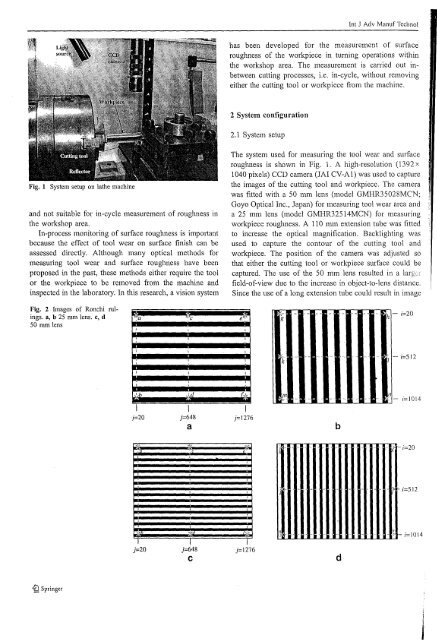
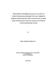
tnt J Adv Manuf Technolhas been developed for the measurement of surfaceroughness of the workpiece in turning operations withinthe workshop area. The measurement is carried out inbetweencutting processes, i.e. in-cycle, without removingeither the cutting tool or workpiece from the machine.2 System configuration2.1 System setupFig. 1 System setup on lathe machineand not suitable for in-cycle measurement of roughness inthe workshop area.In-process monitoring of surface roughness is impoltantbecause the effect of tool wear on surface finish can beassessed directly. Although many optical methods formeasUling tool wear and surface roughness have beenproposed in the past, these methods either require the toolor the workpiece to be removed from the machine andinspected in the laboratory. In this research, a vision systemThe system used for measuring the tool wear and surfaceroughness is shown in Fig. 1. A high-resolution (1392 x1040 pixels) CCD camera (JAI CV-A1) was used to capturethe images of the cutting tool and workpiece. The camerawas fitted with a 50 mm lens (model GMHR35028MCN;Goyo Optical Inc., Japan) for measuring tool wear area anda 25 mm lens (model GMHR32514MCN) for measuringworkpiece roughness. A 110 mm extension tube was fittedto increase the optical magnification. Backlighting wasused to capture the contour of the cutting tool andworkpiece. The position of the camera was adjusted sothat either the cutting tool or workpiece surface could becaptured. The use of the 50 mm lens resulted in a large!field-of-view due to the increase in object-to-Iens distance.Since the use of a long extension tube could result in imageFig. 2 Images of Ronchi rulings.a, b 25 mm lens. c, d50 mm lense'--zg-K··k~1 - i=512,~." ,J4 f,> mFI I Ij=20 j=648 j=1276ab'.t··t!;=1014~f '4;: ".'..,Y~c.,)-;=201;=512;=1014J=20 j=648Cj=1276d
Int J Adv Manuf TechnolTable 1 Distances between measurement points on image (see Fig. 2)(pixels)pointsLens focal lengthTable 3 Machining parametersMachine tool Conventional lathe (Han'ison 600; The 600Group, UK)a-bc-de{g-hk-lm-n25 mm89889989810971098109650mm949949948122812281228WorkpieceCutting toolFeed rateMachining depthCutting speedCoolantMachining timeStainless steel rod, AISI308Uncoated cemented carbide: TPUN-16·03-04_H13A (Sandvik Co, Ltd, Sweden)0.2, 0.25, 0.3, 0.4 mmlrev0.5 mm58 m/minAir5,25,50,75, 100, 125, 150,175,208 mindistortion, the presence of distortion was checked usinghigh precision Ronchi rulings having 200 lines per inch(Edmund Optics Pte. Ltd., Singapore). Separate images ofthe rulings placed in horizontal and vertical positions werecaptured using the 25 mm and 50 mm lenses. The imageswere contrast enhanced and scanned at various pointsshown in Fig. 2a-d. The distances between these pointswere calculated to assess the amount of distortion. Theresults in Table I show that maximum difference indistance between the points is 2 pixels (0.18%). Since theoutput of the CCD camera is in pixels and the surfaceroughness of the workpiece must be determined in J.lm, itwas necessary to determine the horizontal and verticalscaling factors in mm/pixel. These factors were obtainedusing pin gages of known dimensions and are shown inTable 2.2.2 Machining conditionfollowing sub-sections. Detailed description of the algorithmused for tool wear measurement is publishedseparately [IS].3.1 Image acquisitionIn the stage 1, a frame-grabber (DT3162; DataTranslation,Inc., USA) was used to interface the CCD camera to thecomputer. The frame grabber is a digitizer that acts as animage buffer. Output of the CCD camera was captured anddigitized using this frame grabber.Stage 1Several parameters can influence the surface roughness ofthe workpiece and tool wear. These include machiningduration, cutting speed, feed rate, properties ofcutting tool,material of workpiece, and properties of coolant. Table 3shows the parameters used in this study.Stage 2Stage 3Noise removal using Wiener filteringImage thresholding (binarization)3 Description of measurement algorithmThe various stages of the measurement of workpieceroughness are shown in Fig. 3 and are described in theTable 2 Horizontal and vertical scale factorsLens focal Direction Scaling factor Field of view oflength (Il-m/pixel) cameraStage 4Stage 5Stage 6Detecting the profile of surface roughnessDetermining the best fitted lineDetermining the roughness value50 mm Horizontal 1.81 2.3 mm x2 mmVertical 225 mm Horizontal I 1.3 mm x 1.1 mmVertical 1.06Fig. 3 Flowchart of algorithm for roughness measurement©Springer