Laporan Akhir Projek Penyelidikan Jangka Pendek ... - ePrints@USM
Laporan Akhir Projek Penyelidikan Jangka Pendek ... - ePrints@USM
Laporan Akhir Projek Penyelidikan Jangka Pendek ... - ePrints@USM

You also want an ePaper? Increase the reach of your titles
YUMPU automatically turns print PDFs into web optimized ePapers that Google loves.
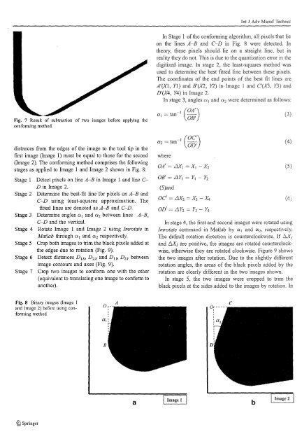
Int J Adv Mannf Techno!In Stage I ofthe confonning algorithm, all pixels that lieon the lines A-B and C-D in Fig. 8 were detected. Intheory, these pixels should lie on a straight line, but inreality they do not. This is due to the quantization error in thedigitized image. In stage 2, the least-squares method wasused to determine the best fitted line between these pixels.The coordinates of the end points of the best fit lines areA'(X!, Yl) and B'(X2, Y2) in Image 1 and C(X3, Y3) andD '(X4, Y4) in Image 2.In stage 3, angles 01 and 02 were determined as follows:Fig. 7 Result of subtraction of two images before applying theconforming method( OA I )0'1 = tan-I OB'(3)distances from the edges of the image to the tool tip in thefirst image (Image 1) must be equal to those for the second(Image 2). The confonning method comprises the followingstages as applied to Image 1 and Image 2 shown in Fig. 8:Stage 1 Detect pixels on line A-B in Image 1 and line cD in Image 2.Stage 2 Detennine the best-fit line for pixels on A-B andC-D using least-squares approximation. Thefitted lines are denoted as A-B and C-D.Stage 3 Detennine angles 01 and 02 between lines A-B,C-D and the vertical.Stage 4 Rotate Image I and Image 2 using Imrotate inMatlab through 01 and 02 respectively.Stage 5 Crop both images to trim the black pixels added atthe edges due to rotation (Fig. 9).Stage 6 Detect distances D 1X , D 2X and D I !5 D 2y betweenimage contours and axes (Fig. 9).Stage 7 Crop two images to confOllli one with the other(equivalent to translating one image to confonn toanother).where( OCI )OD'OA' = LJX J = XI - X 2OB' = LlY, = Y 1 -(5)andY2oC' = LJX2 = X 3 - X 4OD' = LlY 2 = Y 3 -Y4In stage 4, the first and second images were rotated usingImrotate command in Matlab by {XJ and {X2, respectively.The default rotation direction is counterclockwise. If !:0{,and /::0(2 are positive, the images are rotated counterclockwise,otherwise they are rotated clockwise. Figure 9 showsthe two images after rotation. Due to the slightly differentrotation angles, the areas of the black pixels added by therotation are clearly different in the two images shown.In stage 5, the two images were cropped to trim theblack pixels at the sides added to the images by rotation. In(4)(5)(6;Fig. 8 Binary images (Image Iand Image 2) before using confomlingmethodaI Image 1 I bI Image 2 I~ Springer