Laporan Akhir Projek Penyelidikan Jangka Pendek ... - ePrints@USM
Laporan Akhir Projek Penyelidikan Jangka Pendek ... - ePrints@USM
Laporan Akhir Projek Penyelidikan Jangka Pendek ... - ePrints@USM

Create successful ePaper yourself
Turn your PDF publications into a flip-book with our unique Google optimized e-Paper software.
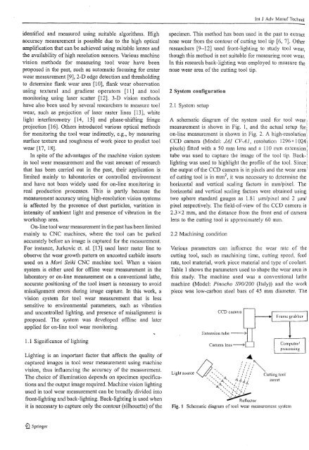
lnt J Adv Manuf Technolidentified and measured using suitable algorithms. Highaccuracy measurement is possible due to the high opticalamplification that can be achieved using suitable lenses andthe availability of high resolution sensors. Various machinevision methods for measuring tool wear have beenproposed in the past, such as automatic focusing for craterwear measurement [9], 2-D edge detection and thresholdingto detennine flank wear area [10], flank wear observationusing textural and gradient operators [II] and toolmonitoring using laser scatter [12]. 3-D vision methodshave also been used by several researchers to measure toolwear, such as projection of laser raster lines [13], whitelight interferometry [14, 15] and phase-shifting fringeprojection [16]. Others introduced various optical methodsfor monitoring the tool wear indirectly, e.g., by measuringsurface texture and roughness of work piece to predict toolwear [17, 18].In spite of the advantages of the machine vision systemin tool wear measurement and the vast amount of researchthat has been carried out in the past, their application islimited mainly to laboratories or controlled environmentand have not been widely used for on-line monitoring inreal production processes. This is partly because themeasurement accuracy using high-resolution vision systemsis affected by the presence of dust particles, variation inintensity of ambient light and presence of vibration in theworkshop area.On-line tool wearmeasurement in the past has been limitedmainly to CNC machines, where the tool can be parkedaccurately before an image is captured for the measurement.For instance, Jurkovic et. al. [13] used laser raster line toobserve the wear growth pattern on uncoated carbide insertsused on a Mori Seiki CNC machine tool. When a visionsystem is either used for offline wear measurement in thelaboratOly or on-line measurement on a conventional lathe,accurate positioning of the tool insert is necessary to avoidmisalignment errors during image capture. In this work, avision system for tool wear measurement that is lesssensitive to environmental parameters, such as vibrationand uncontrolled lighting, and presence of misalignment isproposed. The system was developed offline and laterapplied for on-line tool wear monitoring.specimen. This method has been used in the past to extractnose wear from the contour of cutting tool tip [6, 7]. Otherresearchers [9-12] used front-lighting to study tool wear,though this method is not suitable for measuring nose wear.In this research back-lighting was employed to measure thenose wear area of the cutting tool tip.2 System configuration2.1 System setupA schematic diagram of the system used for tool wear;measurement is shown in Fig. 1, and the actual setup forion-line measurement is shown in Fig. 2. A high-resolution!CCD camera (Model: JA! CV-Al, resolution 1296x 1024;pixels) fitted with a 50 mm lens and a 110 mm extension:tube was used to capture the image of the tool tip. Back-:lighting was used to highlight the profile of the tool. Since)the output ofthe CCD camera is in pixels and the wear areaof cutting tool is in mm 2 , it was necessary to detennine thehorizontal and vertical scaling factors in mm/pixel. Thehorizontal and vertical scaling factors were obtained usingtwo sphere standard gauges as 1.81 I-un/pixel and 2 I-lm/pixel respectively. The field-of-view of the CCD camera is2.3 x2 mm, and the distance from the front end of cameralens to the cutting tool is approximately 60 mm.2.2 Machining conditionVarious parameters can influence the wear rate of thecutting tool, such as machining time, cutting speed, feedrate, tool material, work piece material and type of coolant.Table 1 shows the parameters used to shape the wear area inthis study. The machine used was a conventional lathemachine (Model: Pinocho S901200 (Italy)) and the workpiece was low-carbon steel bars of 45 mm diameter. TheCCD cameraFrame grabber1.1 Significance of lightingLighting is an important factor that affects the quality ofcaptured images in tool wear measurement using machinevision, thus influencing the accuracy of the measurement.The choice of illumination depends on specimen specificationsand the output image required. Machine vision lightingused in tool wear measurement can be broadly divided intofront-lighting and back-lighting. Back-lighting is used whenit is necessary to capture only the contour (silhouette) ofthe(),.4///,:~Light source " ", " " , " Cutting tool... "", .... , ... .::i,.. ),' I ,','....... ", ~ 'II lIJx I insclt.. :::l.....::i... '1:,' / '1'-................ ';' ... ,"- ...:.. /..... ;/~./'~...............ReflcetorFig. 1 Schematic diagram of tool wear measurement system~ Springer