Laporan Akhir Projek Penyelidikan Jangka Pendek ... - ePrints@USM
Laporan Akhir Projek Penyelidikan Jangka Pendek ... - ePrints@USM
Laporan Akhir Projek Penyelidikan Jangka Pendek ... - ePrints@USM

You also want an ePaper? Increase the reach of your titles
YUMPU automatically turns print PDFs into web optimized ePapers that Google loves.
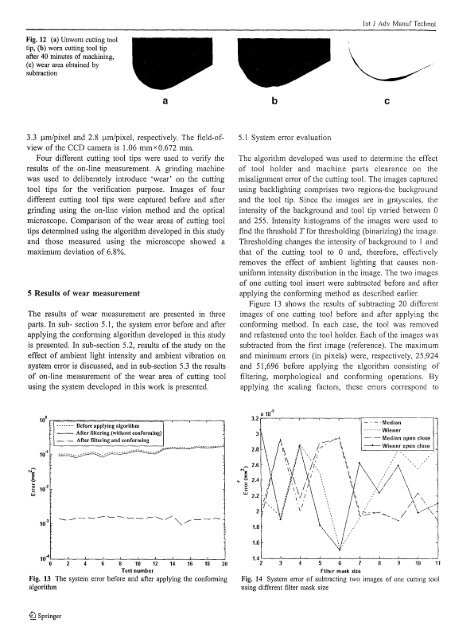
lnt J Adv Manuf TechnolFig. 12 (a) Unwom cutting tooltip, (b) wom cutting tool tipafter 40 minutes of machining,(c) wear area obtained bysubtractiona b c3.3 11m/pixel and 2.8 11m/pixel, respectively. The field-ofviewof the CCD camera is 1.06 mm x 0.672 mm.Four different cutting tool tips were used to verify theresults of the on-line measurement. A grinding machinewas used to deliberately introduce 'wear' on the cuttingtool tips for the verification purpose. Images of fourdifferent cutting tool tips were captured before and aftergrinding using the on-line vision method and the opticalmicroscope. Comparison of the wear areas of cutting tooltips determined using the algorithm developed in this studyand those measured using the microscope showed amaximum deviation of 6.8%.5 Results of wear measurementThe results of wear measurement are presented in threeparts. In sub- section 5.1, the system elTor before and afterapplying the confonning algorithm developed in this studyis presented. In sub-section 5.2, results of the study on theeffect of ambient light intensity and ambient vibration onsystem elTor is discussed, and in sub-section 5.3 the resultsof on-line measurement of the wear area of cutting toolusing the system developed in this work is presented.5.1 System elTor evaluationThe algorithm developed was used to determine the effectof tool holder and machine parts clearance on themisalignment error of the cutting tool. The images capturedusing backlighting comprises two regions-the backgroundand the tool tip. Since the images are in grayscales, theintensity of the background and tool tip varied between 0and 255. Intensity histograms of the images were used tofind the threshold T for thresholding (binarizing) the image.Thresholding changes the intensity of background to I andthat of the cutting tool to 0 and, therefore, effectivelyremoves the effect of ambient lighting that causes nonunifonnintensity distlibution in the image. The two imagesof one cutting tool insert were subtracted before and afterapplying the conforming method as described earlier.Figure 13 shows the results of subtracting 20 di ffcrcntimages of one cutting tool before and after applying theconfonning method. In each case, the tool was removedand refastened onto the tool holder. Each of the images wassubtracted from the first image (reference). The maximumand minimum elTors (in pixels) were, respectively, 25,924and 51,696 before applying the algorithm consisting offiltering, morphological and conforming operations. Byapplying the scaling factors, these enol'S correspond to10° n==============;,-..--..----,,...--,........ Before applying algorithm-- After filtering (withont conforming)- - Arter filtering and conforming10·4'--_'-_'--_'-_'--_'--_'--_'--_'------JL----..Jo 2 4 6 8 10 12 14 16 18 20Test numberFig. 13 The system error before and after applying the conformingalgorithm1.4 2'---'-3--4'----'-5--6'---'-7--'----'-----'10-----'11Filter mask sizeFig. 14 System error of subtracting two images of one cutting toolusing different filter mask size%l Springer