4Channel Stand Alone DVR - iMPath Networks
4Channel Stand Alone DVR - iMPath Networks
4Channel Stand Alone DVR - iMPath Networks

You also want an ePaper? Increase the reach of your titles
YUMPU automatically turns print PDFs into web optimized ePapers that Google loves.
ContentsContentsCHAP. 1 Features & Package Contents ---------------------------------------------------------------- 41-1. Features ---------------------------------------------------------------- 41-2. Package Contents ---------------------------------------------------------------- 5CHAP. 2 Function of Each Button ---------------------------------------------------------------- 62-1. Front ---------------------------------------------------------------- 62-2. Rear ---------------------------------------------------------------- 8CHAP. 3 Installation ---------------------------------------------------------------- 93-1. Installation Configuration ---------------------------------------------------------------- 93-2. Detailed Installation ---------------------------------------------------------------- 101) Rack Mount ---------------------------------------------------------------- 102) HDD(Hard Disk Drive) ---------------------------------------------------------------- 103) Camera ---------------------------------------------------------------- 114) Monitor ---------------------------------------------------------------- 115) Power ---------------------------------------------------------------- 116) VCR, Video Printer ---------------------------------------------------------------- 127) Other External Device ---------------------------------------------------------------- 12CHAP. 4 Operation ---------------------------------------------------------------- 134-1. System Log-in ---------------------------------------------------------------- 134-2. Factory Default ---------------------------------------------------------------- 134-3. Display Configuration ---------------------------------------------------------------- 144-4. Live View Setup ---------------------------------------------------------------- 141) Full / Multiple View ---------------------------------------------------------------- 142) Sequencing Cameras ---------------------------------------------------------------- 153) PIP View ---------------------------------------------------------------- 154) Freeze View ---------------------------------------------------------------- 155) Zoom View ---------------------------------------------------------------- 154-5. Record ---------------------------------------------------------------- 164-6. Playback ---------------------------------------------------------------- 164-7. Search ---------------------------------------------------------------- 174-8. PTZ Camera Operation ---------------------------------------------------------------- 184-9. Data Back-Up ---------------------------------------------------------------- 184-10. Audio Operation ---------------------------------------------------------------- 182
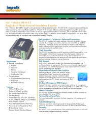
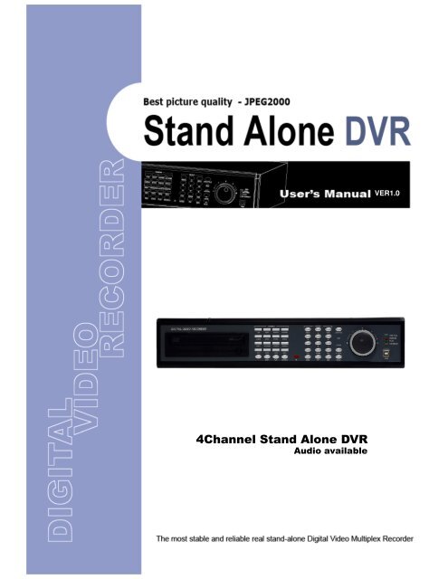
CHAP. 1 Features & Package Contents1-1. FeaturesLive ViewReal time display per cameraAuto SequencePIP (Picture in picture)Event PopupDigital ZoomDisplay FreezeSimple Playback modeSimple PTZ camera controlRecordVariable Record resolution (For higher picture quality or higher recording speed)Efficient Image Quality setup in 5 stepsSchedule Record / Holiday RecordEvent Record (Alarm / Motion)Emergency RecordNetworkView Live and Playback images across IP networkCopy images across the networkPlaybackSearch & Playback by Date/Time, Event and CameraOutstanding picture quality by JPEG 2000 compression algorithm (No mosaic effect)Suitable for recording not only images but also textVarious steps in Forward Playback Speed (X1/16, X1/8, X1/4, X1/2, X2, X4, X16, X32, X64)Various steps in Backward Playback Speed (X1/16, X1/8, X1/4, X1/2, X2, X4, X16, X32, X64)Easy and convenient search by Jog Shuttle & Remote ControllerData Back-UpSimple Back-Up using built-in CD Writer (Back-up CD Player included in the package)Network Back-Up using Remote Viewer program(Remote Viewer included in the package)Supports bigger capacity of HDD (300GB or bigger)OthersMulti-Language (English, Spanish, German, French, Italy, Japan, China)VGA option board supports both TFT LCD monitor and CRT monitorLock the system by PasswordJOG / SHUTTLEPAL/NTSC Auto detectionControl the unit by using Remote ControllerAudio recording : IN-4ch, OUT-1ch (mono)1 Features & Package Contents CHAP.4
ButtonCHAP. 2 Function of Each Button2-1 FRONTof Each Function 2 CHAP.NameFunction1LED Lamps2USB Device3IR4Cameraselection&PTZ cameracontrolShows status of operationFirmware upgrade by connecting PC with latest firmware to USB portIR receiver1. Pressing this button will display a full screen image of that camera2. Control PTZ camera (Each button is assigned for each PTZ command)• ON : LIGHT ON• SET : SET PRESET• OFF : LIGHT OFF• CLEAR : CLEAR PRESET• OPEN : IRIS OPEN• CLOSE: IRIS CLOSE• GOTO : GOTO PRESET• AUTO : AUTO SCAN• NEAR : FOCUS NEAR • F1 : USER 1• FAR : FOCUS FAR • F2 : USER 2• WIDE : ZOOM IN • F3 : USER 3• TELE : ZOOM OUT • F4 : USER 45Record /PlaybackRECSTOPPLAYSEARCHEmergency Record at continuous, 60ips, SUPER FINE sizeStop of Emergency Record and return to Schedule Recordfrom Emergency Record. Playback stop.Playback of recorded data on HDDSearch recorded data on HDD6SETUP MENU Set up for SYSTEM MENU or Use to exit the menuENTERNEXTSelects each menu optionMove to next stepin the menu+ - Reduce or increase the option value in the menuPress MENU button before powering off the unit.6▲▼◀▶ Navigate
NameFunction7LIVE ViewControl8Jog ShuttleControlPTZZOOMFRZMODEPIPSEQK.LOCKQ. Play(Quick Play)AUDIOJ/SHUTTLEOn/Off for PAN/TILT/ZOOM control modePress this button first to control PTZ camera connected to<strong>DVR</strong> unit viaCHAP. 2 Function of Each ButtonRS-485Zooming an imageFreezing an imageSwitch to split displayMODE button changes screen-division from (to) full screento (from) 16-split screen.Display in PIP (Picture in Picture) modeAuto camera image sequencing in full screen modeLock the key function.To unlock, press longer time (for several seconds) and theninput the password.Play from image recorded 2 minutes ago in forwarddirection. (in case recorded in continuous mode).Select audio channelPressing Jog Shuttle button (Ready for use Jog/Shuttle): In playback mode, pressing J. SHUTTLE button makeimages frozen.RUN LED on : While you operate Jog or ShuttleACTIVE LED on : When J. SHUTTLE button is pressed9Jog Shuttle10CD-RWVery easy and convenient search : Press J. Shuttle button, and images inplayback pause, and then Jog and Shuttle makes it very easy and convenientto search, forward or backward, fast and slow, as user want.Data Back-up and Firmware Upgrade using built-in CD writer7
2-2. REARof Each Button Function 2 CHAP.NameFunction1 RS 485 Connection with PTZ Camera or other external device using RS 485interfaceRELAY OutputRelay out terminalSENSOR InputSensor input terminal2 VGA Connection to VGA Monitor (CRT type or TFT LCD monitor)Just in case you purchased <strong>DVR</strong> with VGA option board fixed on the mainboard of <strong>DVR</strong>, you can connect VGA Monitor to <strong>DVR</strong> unit.3 ETHERNET Connection to ETHERNET device4 RS-232C Connection to external device as PC using RS-232C to control the <strong>DVR</strong>5 CAMERA Input Connection with camera6 LOOP Output Camera loop out7 MONITOROutputConnection with Composite Monitor8 VCR Output Connection with VCR for analog backup9 DC Power DC 12V 8.3A Adaptor (Refer to the Instruction for adapter by HDDscapacity)10 POWERSWITCHPower ON/OFF switch for adapters11 Audio Input MicrophoneTo avoid accidental deletion of HDD data, please make sure to press MENU button before powering off the unit. This takes the unit out of record mode for safe shutdown. Input (4ch)8Output (1ch) SpeakerAudio Output
CHAP. 3 InstallationCHAP.3 Installation3-1. Installation Configuration9
3-2. Detailed Installation1) Rack mountCHAP. 3 Installation1. Remove 4 bolts on each side cap toinstall rack mount.2. Attach rack mount bracket to <strong>DVR</strong>.3. Attach <strong>DVR</strong> with rack mount bracket to 19” rack.2) HDD1. Connect Main Board and HDD1 using IDE cable and HDD power cable.2. The jumper setting of HDD1 should be on Master if you install only one HDD.3. The jumper setting of HDD1 should be on Master and HDD2 should be on Slave if you installtwo HDDs.(Refer to the above figure)4. Stick the HDD absorber (included in package) on the bottom of case and then install the HDDon top of them by using the bolts (included in package).5. Screws must be inserted from outside of the case bottom.10
3) CameraCHAP. 3 InstallationConnect cameras to the camera input on rear panel of <strong>DVR</strong> marked CAMERA IN.4) Monitor5) PowerConnect the video output marked MONITOR to Video-In of Main monitor.Connect one DC 12V, 8.3 A Adaptor to the back side of Power Jack for right operation of 2HDDsand CDRW.Before you turn on the Power switch, be sure all necessary devices such as Poweradaptor, cameras and Monitor are connected properly to <strong>DVR</strong>!NoticeTo avoid accidental deletion of HDD data, please make sure to press MENU buttonbefore powering off the unit. This takes the unit out of record mode for safe shutdown.11
6) VCR, VIDEO PRINTERCHAP. 3 InstallationConnect VCR or VIDEO Printer to VCR out on the rear panel of <strong>DVR</strong>.7) Other External DeviceRS-232C : Control <strong>DVR</strong> through RS-232C port by using PC.RS-485 : Control external device like PTZ CameraRELAY Output : Relay OutputSENSOR Input : SENSOR Input (Alarm connection)ETHERNET : Connection to LAN, WAN, Internet.VGA : Connection to a VGA monitor(CRT,TFT LCD) if optional VGA board is fixedon the main board as shown in the following figure.Resolution set by manufacturer is 800x600 60 Hz, and user can set resolutionin MONITOR SETUP / VGA SETUP / VGA RESOLUTION.Audio Input : Microphone input (IN1~IN4)Audio Output : Speaker Output (OUT)12
4-1. System Log-In1) To enter into the setup menu, press the [MENU] button.4 Operation<strong>DVR</strong> LOG-INCHAP.2) Enter password with channel number buttonfrom No.1 to No.10 on the front of the <strong>DVR</strong> unit.(Maximum of 8 digits are available)3) After inputting the password, press the [ENTER] button.ENTER PASSWORD : _ _ _ _ _ _ _ _INPUT YOUR OWN PASSWORDTO EXIT, PRESS [MENU]Administrator :If the password entered matches previously set password, “ LOGIN ADMIN” message appears andyou can enter into SYSTEM SETUP.If the password entered does not match previously set password, the <strong>DVR</strong> unit goes back to livedisplay mode.Factory default password is blank. For log-in, just press [MENU] button and then [ENTER] button.-Factory default passwordADMIN : (Blank)MANAGER : ‘ 1 ’USER 1~USER8 : ‘ 2 ’ ~ ’ 9 ’※We recommend configuring a unique password as per the procedure inSYSTEM MENU - CONFIGURATION - PASSWORD SETUP.※For security reasons, be sure to make note of your own password.4-2. Factory DefaultBefore first operation, you must set Time/Date, set FACTORY DEFAULT, and then clearHDD, even though it is brand new one. It is to make DVMR system and HDD ready forproper operation. Starting recording without FACTORY DEFAULT setting and HDD clear willcause malfunction.1. HDD CLEARDISPLAY SETUPCONFIGURATIONREOCRD SETUPBACK-UPEXTERNAL DEVICEFACTORY DEFAULTLANGUAGEHDD MANAGEMENTTIME/DATE SETUPCAMERA SETUPINTERVAL SETUPALARM SETUPEVENT POPUP SETUPBUZZER SETUPPASSWORD SETUPSYSTEM IMFORMATION2. FACTORY DEFAULTDISPLAY SETUPCONFIGURATIONREOCRD SETUPBACK-UPEXTERNAL DEVICEFACTORY DEFAULTLANGUAGERefer to page 22.Refer to page 31.13
4-3. Display ConfigurationCHAPHDD StatusIn live mode : Amount of data recordedIn Playback mode : Amount of data playedOperationETHERNET statusConnected4.DisconnectedCurrent Time & DatePIPFREEZESEQUENCEZOOMAUDIOStatus of <strong>DVR</strong> systemEmergency Record (Red)Schedule Record (Green)Record Stop (White)StopForward PlaybackBackward PlaybackPause1/16~1/2x forward playback1/16~1/2x backward playback2~4x forward playback2~4x backward playback16~64x forward playback16~64x backward playbackALARM RecordMOTION RecordCONTINUOUS Record60(50) IPS @ 720x240(720x288)120(100) IPS @360x240(360x288)240(200) IPS @360x120(360x144)LIVE DisplayCamera TitlePicture QualityBASICNORMALENHANCEDFINESUPER FINE4-4. Live View Setup1) Full / Multiple ViewSwitch to multi-screen display by pressing [MODE]. For full image display, just press the channel buttonwhich you want or [MODE] button again.When you playback images which recorded in 360X240(360X288), 360X120(360X144) resolution,only 4 split screen is available.Full screenMulti -ScreenFull screen[MODE][MODE] or Channel button14
CHAP. 4 Operation2) View in SequencePress [SEQ] button. It automatically displays full screen images in sequence.CH03CH02CH01CH04●●●3) Picture in Picture(PIP View)When it is in full screen display mode, you can see other camera in a smallwindow by pressing [PIP].The other camera in small window is rotating insequence to next number of camera and you can set the rotating timeinterval as per the procedure in SYSTEM MENU-CONFIGURATION-INTERVAL SETUP.CAM-0124) Freeze ViewFull display mode : If you press the [FRZ] button, the FRZ icon will be activated on thescreen and “F” character will be shown beside camera title, andlive image will be frozen.Split display mode : If you press the [FRZ] button, the FRZ icon will be activated on thescreen. press the channel button which you want to freeze.To release frozen image, press channel number of frozen image againand press [FRZ] button to exit FRZ mode.5) Zoom ViewIn full screen, press the [ZOOM] button and move the Selection Frame using J.SHUTTLE or Directionkeys to the area which you want to enlarge. And then press the [ENTER] button for 2-times enlargedpicture. To exit Zoom mode, just press [ZOOM] button again.Horizontal Movement : J.SHUTTLEVertical Movement : Hold [UP or DOWN] button and turn J/SHUTTLE15
4-5. RecordRecording mode set before delivery by manufacturer (Default recording mode) is Schedule Recording.In this default recording mode, it records 24 hours/day continuously in weekday and on the weekend.Once you press the [REC] button while you see live view, the record type is changed to Emergency Record mode.Operation 4 CHAP.- Emergency Record : at full resolution/in best qualityRecord type : CONTINUOUS, SUPER FINE quality,60 (50) ips at 720X240 (720x288)- Schedule RecordRecord and stop as set (time interval andrecord type) in RECORD-SCHEDULE SETUP menu.- Stop RecordRecording stopped as set inRECORD-SCHEDULE SETUP menu.Emergency Record [RED]Schedule Record [GREEN]Stop Record [WHITE]On the screen- Emergency Record: Red Record Icon ( ) and Record LED is lit- Schedule Record: Green Record Icon ( ) and Record LED is lit- Record Stop: White Icon ( ) and Record LED is off- Motion Record, Alarm Record, Alarm+Motion Record: Record standby LED blinks: Record LED is lit※While in Emergency Record mode, press [STOP],[PLAY], [MENU], or [SEARCH] button to exit fromEmergency Recording mode and return to ScheduleRecord mode.※For details, refer to the SYSTEM MENU – RECORDSETUP (Page 27)- This <strong>DVR</strong> unit does not record in following conditions ;※While entered in the Menu.※No camera is connected※Overwriting is off in the Record Setup menu.4-6. PlaybackOn record mode or stop mode, press [PLAY] button to play the recorded data in 1x speed.For backward playback, press [PLAY] button again.Use Jog/Shuttle to pause and control playback speed. To stop playback, press the [STOP] button.Using Jog/Shuttlepress the [J.SHUTTLE] button in playback mode. The [ACTIVE] LED will be lit, and Jog/Shuttle is readyfor use. The [RUN] LED will blink whenever you operate the Jog/Shuttle.For forward playback, turn the Shuttle right and turn Shuttle left for backward playback.Turn Jog using your index figure to see picture by picture in forward or backward direction.Operation of Shuttle is as follows.1/4 x : 4 times slower than normal playback speed1/2 x : 2 times slower than normal playback speed1 x : Normal playback speed2 x : 2 times faster than normal playback speed4 x : 4 times faster than normal playback speed16 x : 16 times faster than normal playback speed64 x : 64 times faster than normal playback speedIf you want to keep the playback speed you selected using Shuttle, just hold the shuttle at that location for a fewseconds, and playback in speed you selected continues until you rotate Shuttle again.16
4-7. Search4 OperationPress [SEARCH] button, and 3 different methods for searching recorded data are available as shownin following SEARCH window. For selecting searching method, use direction key or Jog/Shuttle.After selecting each search method, press [ENTER] button for playback. exit, press [MENU] button.CHAP.1) SEARCH BARSearch by percentage of total recorded data. It starts from image corresponding to set % of dataon the search bar.2) TIME/DATESearch by time & date. Playback starts from the time & date selected.3) EVENT LISTSearch by event list (Motion, Alarm, Video Loss).SEARCHRECORD SEARCH BARSEARCH BARTIME/DATEEVENT LIST[TARGET PERCENT]020 %SELECT MENU : ▲▼, & [ENTER]SEARCH pageSEARCH : [ENTER], EXIT : [MENU]SEARCH BAR pageTIME/DATEEVENT LISTCH EVENT TIME/DATE 001/000[START] 2005/JUN/20 AM04:04:12[ END ] 2005/JUN/20 PM08:12:23INPUT TIME/DATE2005/JUN/07 AM04:04:12---------------------------------------------------- / - -/ ------ / - -/ ------ / - -/ ------ / - -/ ------ / - -/ ------ / - -/ ------ / - -/ ------ / - -/ ---- : -- : ---- : -- : ---- : -- : ---- : -- : ---- : -- : ---- : -- : ---- : -- : ---- : -- : --SEARCH : [ENTER], EXIT : [MENU]TIME/DATE pageSEARCH : [ENTER] , EXIT : [MENU]EVENT LIST page4-8. PAN/TILT/ZOOM Camera OperationPress [PTZ] button first for PTZ control mode. Numeric buttons from 1 to 16 and direction buttons areassigned for each PTZ command, and user can control PTZ camera connected to <strong>DVR</strong> unit bypressing any one of those 20 buttons, one after the other, as needed, and it is just like control byseparate PTZ controller.17
4 Operation CHAP.Button PTZ command Button PTZ command1/ON LIGHT ON 10/CLEAR PRESET CLEAR2/OFF LIGHT OFF 11/GOTO PRESET GOTO3/OPEN IRIS OPEN 12/AUTO AUTO SCAN4/CLOSE IRIS CLOSE 13/F1 ~ 16/F4 FUNCTION5/NEAR FOCUS NEAR UP BUTTON TILT UP6/FAR FOCUS FAR DOWN BUTTON TILT DOWN7/WIDE ZOOM IN LEFT BUTTON PAN LEFT8/TELE ZOOM OUT RIGHT BUTTON PAN RIGHT9/SETPRESET SET4-9. Data Back-UpEnter into SYSTEM MENU-BACKUP-CDR SETUP.1) Insert empty CD-R media into CD writer and select the start time & date from which you want to back up.※The START & END time / date in HDD sub-menu only shows start and end of recording.This is not selectable and editable.※700MB on CD-R sub-menu represent size of CD-R media inserted.2) To set start time of back-up and back-up data size, press the [ENTER] button first on [START] or [SIZE]sub-menu and adjust using [+] or [-] button and move using [LEFT] and [RIGHT] button for nextchange. After setting the time & date and back-up data size, press the [ENTER] button again to exit.※End of back-up time will be calculated automatically as per start time & date and the back-updata size you set.※User can select the back-up data size (size of back-up data from start of back-up) on [SIZE] item butEND of back-up time is automatically determined by <strong>DVR</strong> system.3) Press [ENTER] button on BURN sub-menu. <strong>DVR</strong> system starts burning CD.4) When burning is completed, CD-R media will come out automatically. In the next CD back-up, starttime of CD-R shall be the end time of previous CD-back-up, and you can back-up from that forcontinuous data back-up. If you need another backup, repeat the above procedure. To stop backup,press the [MENU] button.※During burning CD, it’s impossible to cancel burning process.5) User can verify the back-up CD on PC with BACK-UP CD PLAYER (Included in Package).CD-R SETUPHDD[START] 2005/AUG/07 AM04:04:12[ END ] 2005/AUG/08 PM08:12:23CD-R[START] 2005/AUG/07 AM04:04:12[ END ] 2005/AUG/08 PM08:12:23[ SIZE ] 000MBBURNCD-R SETUPHDD[START] 2005/AUG/07 AM04:04:12[ END ] 2005/AUG/08 PM08:12:23CD-R 700 MB[START] 2005/AUG/07 AM04:04:12[ END ] 2005/AUG/08 PM08:12:23[ SIZE ] 700 MB - > 700MBBURNCD-RW BURNING : IMAGE DATA.EXIT : [MENU]EXIT : [MENU]4-10. Audio OperationPress [AUDIO] button to select audio channel..Ch1, Ch2, Ch3, Ch4 or silence in due sequence.※Sound of the selected audio channel comes out in Live display.Recorded sound comes out in Playback.18
CHAP. 5 Set UpCHAP. 5 Set Up5-1. Entering into the MenuEnter into SYSTEM MENU by pressing [MENU] button.ButtonMENUFunctionEnter into SYSTEM MENU, Move to previous menu, ESCENTERNEXTUPDOWNLEFTRIGHTMINUS [-]PLUS [+]Jog ShuttleSelection key, Move to sub-menu, change status (ON or OFF)Move to next pageMove to upper sideMove down sideMove to the leftMove to the rightDecrease the option valueIncrease the option valueJog left turning : Move backward to next image / Decrease valueJog right turning : Move forward to next image / Increase valueShuttle left turning : Decrease playback speed / Decrease valueShuttle right turning : Increase playback speed / Increase valueSCREEN DISPLAYMONITOR SETUPDISPLAY SETUPSYSTEM MENURECORD CONFIGURATIONSCHEDULE SETUPHOLIDAY SETUPHDD MANAGEMENTTIME/DATE SETUPCAMERA SETUPINTERVAL SETUPALARM SETUPEVENT POPUP SETUPBUZZER SETUPPASSWORD SETUPSYSTEM INFORMATIONCONFIGURATIONRECORD SETUPBACK-UPEXTERNAL DEVICEFACTORY DEFAULTLANGUAGEENGLISHSELECT MENU : ▲▼, & [ENTER]SYSTEM MENUTCP/IP SETUPRS-232C SETUPPAN/TILT SETUP19
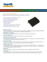
CHAP. 5 Set Up5-2. DISPLAY SETUPSetting up parameters for monitor and display on screen.Enter into SYSTEM MENU-DIPLAY SETUP.DISPLAY SETUPSCREEN DISPLAYMONITOR SETUPLIVEPLAYBACKVGA SETUPCOLOR BAR TESTSELECT MENU : ▲▼,& [ENTER]1) SCREEN DISPLAY1 23 45Setting up the screen display in LIVE modeand PLAYBACK mode.Select the sub-menu which you would like to set usingdirection buttons and then change ON/OFF with[ENTER] button.1. TIME/DATE : Display time & date2. <strong>DVR</strong> STATUS : Display system setting status3. ICON DISPLAY : Display function setting status4. REC/PLAY BAR : Display record / playback status5. CAMERA TITLE : Display camera title2) MONITOR SETUPVGA SETUP : VGA option card enables to connect TFT LCD monitor or CRT type PC monitor to<strong>DVR</strong> unit. To connect TFT LCD monitor or CRT type PC monitor to <strong>DVR</strong> unit, selectresolution as follows using [+] or [−] button. After setting the below option, press[ENTER] button then the <strong>DVR</strong> unit will set VGA resolution automatically.VGA option card supports following resolution, and choose best resolution thatmatch TFT LCD monitor or CRT type PC monitor to be connected to <strong>DVR</strong> unit.- 640X480 / 60Hz - 640X480 / 75Hz ※NOTICE : In the booting process,- 800X600 / 60Hz - 800X600 / 75Hz <strong>DVR</strong> unit with VGA option- 1024X768 / 60Hz - 1024X768 / 75Hz card takes some secondsmore to set parameters.COLOR BAR TEST : Adjust color tone of monitor.(Color bar test is Not available for monitor through VGA)20
CHAP. 5 Set Up5-3. CONFIGURATIONVarious parameters for system can be set in CONFIGURATION menu.Enter into SYSTEM MENU-CONFIGURATION and press the [ENTER] button.CONFIGURATIONHDD MANAGEMENTTIME/DATE SETUPCAMERA SETUPINTERVAL SETUPALARM SETUPEVENT POPUP SETUPBUZZER SETUPPASSWORD SETUPSYSTEM INFORMATIONHDD SETUPHDD INFORMATIONCAMERA TITLECAMERA SETTINGCAMERA ACTIVE SETUPMOTION SETUPSELECT MENU : ▲▼,1) HDD MANAGEMENT& [ENTER]Enter into SYSTEM MENU-CONFIGURATION-HDD MANAGEMENT and press the [ENTER] button.(1) HDD SETUPThis page includes information about start and end of recording, location of recorded data, or locationof last playback on HDD. In addition, users can delete all the data on HDD.HDD SETUPSTATUS HDD DATE/TIME----------------------------------------------------------------------BEGIN MASTER 2005/04/0812:12:05RECORD MASTER 2005/04/0915:09:58PLAY MASTER 2005/04/0819:44:31HDD STATUSHDD CLEARNORMALIN USEOn the [HDD CLEAR] sub-menu, press the [ENTER]button to delete all image data on HDD.The system will ask password for verification.After you clear all data on HDD, status of HDD CLEARchanges from IN USE to EMPTY.※When you clear HDD, event list is deleted, too.ENTER PASSWORD : ________INPUT YOUR OWN PASSWORD.TO EXIT, PRESS [MENU]OKEMPTYHDD CLEAR [ENTER], EXIT [MENU]If you selected OVERWRITE in Record Setup, the HDD STATUS presented as OVERWRITE.(2) HDD INFORMATIONThis menu will show the physical informationof HDD in <strong>DVR</strong>.[MASTER]MODELSPEEDSIZESTARTEND[SLAVE]MODELSPEEDSIZESTARTENDHDD INFORMATION: Maxtor 6Y080L0: PIO-4: 81,964,302,336 BYTES: 2005/04/08 12:08:56: 2005/04/08 12:08:56: AT5520026DT: 240/120nsec: 80GB: 2005/04/08 12:08:56: 2005/04/08 12:08:56TO EXIT, PRESS [MENU]21
2) TIME/DATE SETUPSet time and date of <strong>DVR</strong> system which is veryimportant for search with time and date of the event.Time and date set by manufacturer is different fromlocal time of user, and user must set time and dateexactly in the first operation. Set time & date usingdirection buttons and [-][+] button or Jog shuttle2.Change the date, time and month format foruser’s convenient3) CAMERA SETUPYEARMONTHDAYHOURMINUTESECONDDATE FORMATTIME FORMATMONTH FORMATSELECT : ▲▼,5 Set UpTIME/DATE SETUPCHAP.2005 / JUN /11PM14:06:45ASIA12 HOURENGLISHCHANGE VALUE : - +CAMERA SETUPCAMERA TITLE SETUPCAMERA TITLECAMERA SETUPCAMERA ACTIVE SETUPMOTION SETUP0123456789 .ABCDEFGHIJKLMNOPQRSTUVWXYZ ! #-[ ]*+ -,./ :?@▶◀CAMERA01 CAM -1CAMERA02 CAM -2CAMERA03 CAM -3CAMERA04 CAM -4SELECT MENU : ▲▼,& [ENTER][ENTER] SELECT MODE[▲/▼] select CAMERA(1) TITLE : Input Title of each camera. Move to channel you want to change using [LEFT] or [RIGHT]direction button and then change the title using [-] [+] button. When modification is finished,press the [ENTER] button. To exit to previous menu, press the [MENU] button.(2) COLOR : Adjust image colorMove to each element using[UP][DOWN] button and adjust using[-] [+] button or Jog shuttle.CHANNEL : Select cameraBRIGHTNESS : Adjust image brightness (-32~ 31)CONTRAST : Adjust color contrast ( -32 ~ 31)SATURATION : Adjust color saturation ( -32 ~ 31)HUE : Adjust color hue ( -32 ~ 31)CHANNELBRIGHTNESSCONTRASTSATURATIONHUESELECT : ▲▼,CAMERA COLOR SETUP1+0+0+0+0CHANGE VALUE : + -22
CAMERA ACTIVE SETUPMOTION CONFIGURATIONCH STATUS LIVE REC---------------------------------------------------------------------------01020304ACTIVEACTIVELOSSACTIVEONONOFFONONONOFFOFFCHANNELSENSITIVITY GRADEMOTION DISPLAY TYPERECORD DURATION5 Set Up01CHAP.01OFF05 SECSELECT : ▲▼◀▶,& [ENTER]SELECT ▲▼,CHANGE VALUE : + -(3) CAMERA ACTIVE SETUP : With direction button, move to option to be changed, and press [ENTER]button to select [ON/OFF]. If it is set at LIVE [OFF] and REC [ON], <strong>DVR</strong>system records, but does not show live image of set channel.- STATUS : Shows if image from a specific channel is coming for live display and recording. In normalcamera condition, it is ACTIVE, but LOSS is displayed when the cable is disconnected orcamera is not working.- LIVE : Decides whether to show LIVE screen image or not.- REC : Decides whether to record relevant channel or not.(4) MOTION SETUP: You can set sensitive of motion detection in 4 steps, motion detection area and othersin relation to motion recording in this menu.(4)-1. MOTION SETUP- SENSITIVITY GRADE : Adjusts motion detection sensitivity. (LOW, MEDIUM, HIGH, VERY HIGH)- MOTION DISPLAY TYPE : Showing cells with motion detected differently from cells with no motion .- RECORD DURATION : Whenever motion is detected and it is set at Motion Recording mode, <strong>DVR</strong>system records for RECORD DURATION from time motion is detected.(1sec. ~ 99 sec.) (Default duration : 5 sec.)(4)-2. MOTION MASK SETUP: Set motion detection area. Direction button is for moving and [ENTER]button is for selection, and [MODE] button is for changing mode of MASK SETUP.- CELL : Move to the location which you want to detect and then press the [ENTER] button.Highlighted cell area means motion detection area.- ALL ON : Set all cells as detection area. Use [ENTER] button to set.- ALL OFF : Set all cells as no-detection area. Use [ENTER] button to set.- BLOCK ON : Select detection area by block. Use [MODE] button and press [ENTER] button to set ON.- BLOCK OFF : Select un-detection area by block. Use [MODE] button and press [ENTER] button to set ON.Highlighted Area(Motion Detection Area)Non-highlighted Area(No Motion Detection Area)23
4) INTERVAL SETUPSet the switching time interval for SEQ or PIPfunction.(1 sec. ~ 99 sec.)(1)FULL SCREEN : set the sequencing switch time intervalin live full screen.INTERVAL SETUPSWICHING INTERVALFULL SCREENPIP SCREENEVENT RECORDEVENT UPDATE TIME5 Set Up: 01 SECCHAP.: 01 SEC: 01 SEC(2)PIP SCREEN : set the sequencing switch time intervalof PIP window.SELECT ▲▼◀▶,CHANGE VALUE : - +(3)EVENT UPDATE TIME : Set the minimum time interval of event to be listed in EVENT LIST.If EVENT UPDATE TIME is set at 20 sec, only following event happened20 sec or more than 20 sec later previous event shall be listed in EVENT LIST.5) ALARM SETUPSet type of alarm sensors connected to <strong>DVR</strong> unit.N.O represents Normal Open type and N.C NormalClose type.(1) ALARM INPUT : Select type of alarm sensorconnected to <strong>DVR</strong> unit (N.O or N.C).Use direction button and [-] [+] buttonto set.DISABLE represents not to use alarmsensor connected to <strong>DVR</strong>.(2) DURATION : Set the duration of alarm when analarm is activated. (0 sec. ~ 300 sec.)CHANNELALARM INPUTDURATIONALARM SETUPN.O ................................ NORMAL OPENN.C ................................ NORMAL CLOSE___ .................................. DISABLESELECT : ▲▼,CHANGE VALUE : - +CH1N.O0056) EVENT POPUP SETUPWhen event is activated, the full image will pop upas user set.(1)CHANNEL : Choose a channel(2)POPUP ON/OFF : Set a popup function at ON/OFF(3)EVENT : Set event mode which ‘popup’ function isapplied to.*A : ALARM event. M : MOTION event.EVENT POPUP SETUPCHANNELPOPUP ON / OFFEVENTDURATIONCH01ONAM0 3(4)DURATION : Set the duration how long the popupImage is shown.(0 sec. ~ 60 sec.)more than 2 channels pop up at the same time, the first channel out of them will be shown. (For e.g. Ch1 and CH3 pop up at the same time, ※IfSELECT : ▲▼,CHANGE VALUE : - +CH1 will be shown)24
6) BUZZER SETUPSet parameters for buzzer (On or Off).Use direction button and [ENTER] button.KEY BEEP : buzz when button is pressed.VIDEO LOSS : buzz when video signal is lost.ALARM ACTIVE : buzz when alarm is activated.MOTION DETECT : buzz when motion is detected.ALLKEY BEEPVIDEO LOSSALARM ACTIVEMOTION DETECTBUZZER SETUP5 Set UpONCHAP.ONONONONUser can set all buzzers at On/Off at onceby set ALL at ON/OFF.7) PASSWORD SETUPSet user ID and password.-Use [UP] and [DOWN] button to move to optionand [LEFT] and [RIGHT] button to set user ID.SELECT : ▲▼, &[ENTER]The password must be consist of 1 to 8 digitnumber. Just use numbers button from 1 to 10on the front panel of <strong>DVR</strong> unit.-To change password, user must input currentpassword and then input new password.And input again new password to confirm.USER I DUSER PWNEW PWCONFIRMPASSWORD SETUPADMIN---------------------------------------------------------------- Default valueADMIN : ‘ ‘ (Blank)MANAGER : ‘1’USER 1 : ‘2”::USER 8 : ‘9’[K1-K10] INPUT PASSWORD[ENTER] CHANGE PASSWORDTO EXIT, PRESS [MENU]※Change the user PASSWORD in the first operation is recommended.※In case you forgot PASSWORD, contact dealer of <strong>DVR</strong> to get instruction to enter into menu toset new PASSWORD.8) SYSTEM INFORMATION<strong>DVR</strong> system information including firmwareversion, hardware version, product ID, etc….SYSTEM INFORMATIONS/W VERSION VER 1.0H/W VERSION VER 1.0PRODUCT ID01S-2039-001008-AR-01MASTERMaxtor 6Y060L0SLAVECD-RSAMSUNG CD-R/RW SW-256BTO EXIT, PRESS [MENU]25
5-4. RECORD SETUPThis is the most important configuration of the <strong>DVR</strong>.Enter into SYSTEM MENU-RECORD SETUPand press the [ENTER] button.1) RECORD CONFIGURATIONUse direction button to move and [-] [+] button to set value.RECORD CONFIGURATIONSCHEDULE SETUPHOLIDAY SETUP5 Set UpRECORD SETUPCHAP.(1) OVERWRITE : Set overwrite or stop recording whenthe HDD is full.(2) MULTIPLEX- DUPLEX : Playback & Ethernet- TRIPLEX : Playback & Recording & Ethernet※Note: DUPLEX MODE is recommended to playbackthe images at a maximum frame rate.But, it makes <strong>DVR</strong> not to record during search.(3) QUALITY : Set recording picture quality.Actually it is fixing maximum data size ofimage for each picture quality in 5 stepsas follows.- BASIC- NORMAL- ENHANCED- FINE- SUPER FINE: Default quality set by manufacturerIn Emergency recording mode, recording quality isSUPER FINE.To send more images via IP network and longer recordingtime, set QUALITY at NORMAL or ENHANCED andrecord at 360x240(360x288).OVERWRITEMULTIPLEXQUALITYRESOLUTIONSELECT MENU : ▲▼, & [ENTER]RECORD CONFIGURATIONRECORD IN ALARMRECORD IN MOTIONCONTINUOUS RECORDSELECT MENU : ▲▼,※Data size of image in PAL system is a little bigger than NTSC system, but the total recording timeis same as in NTSC system.ONTRIPLEXENHANCED60IPS 720*2401/1X1/1X1/1XCHANGE VALUE : + -(4) RESOLUTION : Set recording resolution.- 60 ips at 720x240(NTSC) , 50 ips at 720x288(PAL)- 120 ips at 360x240(NTSC) , 100 ips at 360x288(PAL)- 240 ips at 360x120(NTSC) , 200 ips at 360x144(PAL)※It is not possible to see those images in full screen mode in playback.Recording in Dual resolution is recommended for higher recoding speed, and also to sendmore images via IP network.(5) RECORD IN ALARM : Set record speed (skip rate) in ALARM record mode.(6) RECORD IN MOTION : Set record speed (skip rate) in MOTION record mode.(7) CONTINUOUS RECORD : Set record speed (skip rate) in CONTINUOUS record mode.Set record speed (skip rate)- 1/1x, 1/2x, ………. 1/999x record speed- ex: 1/2x ) R->S->R->S… - ex: 1/3x ) R->S->S->R->S->S->R…- ex: 1/4x ) R->S->S->S->R->S->S… ( R : RECORD S : SKIP )- ex : If record resolution is set at 360x240, 1/1x = 120 ips, 1/2x = 60 ips, 1/3x = 40 ips, etc.26
2) SCHEDULE SETUP5 Set UpUnless you selected other recording mode, <strong>DVR</strong> system records in Schedule Recording mode.In SCHEDULE REC SETUP, you set type of recording for every time interval of 2 hours in each day ofthe week. Schedule Recording set by manufacturer is recording continuously at its full recordingspeed, and it means <strong>DVR</strong> system record continuously at 60 ips in total at 720x240 resolution.To set Schedule Recording parameters, enter into SYSTEM MENU-RECORD SETUP-SCHEDULE SETUPand Press the [ENTER] button.CHAP.(1) SCHEDULE SETUPSet recording type for each recording time interval for a day of the week (2 hours interval).00-0202-0404-06-M -- M -SCHEDULE REC SETUPMONAM -AM -SUN-M-AM-TUE- -C- -C- -CWED- -C-- - C- - CTHU- -C-- - C- - CFRI- -C- -C- -CSAT- -C- - C- - CUse [MODE] button to select edit type and move tothe time interval of a day of the week you want to change.Press [ENTER] button to select and use [+] or [−] button,to change the record type. To go next page, use [NEXT]button.06-0808-1010-12-M -- - --- -AM-AM-AM--- C- -C-- - C-- C- - C- - C- - C- - C- - C-- C- -C- -CMODE: CELL BY CELL▲▼◀▶& [NEXT], EDIT:+ -&[MODE]A:ALARM M:MOTION C:CONTINUES-- C- - C-- C1 / 2※MODE (Edit type)TIME CELL : Set each time interval of a day of the weekWEEK : Set a day of the week at onceTIME ZONE : Set a time slot at onceALL : Set page by page at onceCLEAR ALL: Clear page by page※Unless user press [REC] button to record at full resolution and in SUPER FINE picture quality,<strong>DVR</strong> system records in SCHEDULE Record mode.※DEFAULT record mode for each time interval of a day of the week set by manufacturer isCONTINUOUS recording.※Record type :After power on Schedule recordExit from menu Schedule recordEnd of search or playback Schedule recordAfter pressing [STOP] button Schedule recordAfter pressing [REC] button Emergency record (Continuous recording in full performance)[60(50) ips at 720x240(720x288)]3) HOLIDAY SETUP HOLIDAY SETUPUsers can set national holiday or holidays oncalendar to record just as setting for Sunday inSCHEDULE REC SETUP.Use [MODE] button to select a month and directionbutton to move to a day, and press [ENTER] button toset a holiday. Then color of date shall be changed tored, as Sunday.EDIT HOLIDAY : Set as holidayCLEAR MON DATA : Cancel the holiday set per monthCLEAR ALL DATA : Cancel all holiday set※The maximum holidays is 100 days.27< APR > 000/100SUN MON TUE WED THU FRI SAT01 0203 04 05 06 07 08 0910 11 12 13 14 15 1617 18 19 20 21 22 2324 25 26 27 28 29 30MODE : EDIT HOLIDAYSELECT ▲▼◀▶, EDIT [ENTER]&[MODE]
5-5. BACK-UP5 Set UpUser can back up the recorded data to CD using CD writer installed in <strong>DVR</strong>.Refer to [START] and [END] of data on HDD and set copy from time, [START], and size of datacopied, [SIZE], and move to BURN and press [ENTER] button to start copy.CHAP.CD-R SETUPHDD[START] 2005/AUG/07 AM04:04:12[ END ] 2005/AUG/08 PM08:12:23CD-R[START] 2005/AUG/07 AM04:04:12[ END ] 2005/AUG/08 PM08:12:23[ SIZE ] 000MBBURNCD-R SETUPHDD[START] 2005/AUG/07 AM04:04:12[ END ] 2005/AUG/08 PM08:12:23CD-R 700 MB[START] 2005/AUG/07 AM04:04:12[ END ] 2005/AUG/08 PM08:12:23[ SIZE ] 700 MB - > 700MBBURNCD-RW BURNING : IMAGE DATA.SELECT : SETUP BUTTON, JOG SHUTTLESELECT : SETUP BUTTON, JOG SHUTTLESystem Status Messages :- CD-RW DOOR CLOSE. CHECKING CD-R : Blank CD check- INPUT BLANK CD : CD writer has no blank CD.- CD-RW DOOR OPEN : Open CD-RW and insert blank CD –R media into CD drive.- CD-R MEDIA IS DETECTED : Blank CD-R media has been inserted and detected. <strong>DVR</strong> system willdisplay size of blank CD-R.After you set [START] time and [SIZE] in CD-R sub-menu and then select BURN, <strong>DVR</strong> system startscopying images to CD and shows following message.CD-RW BURINING STARTCD-RW BURNING : LEAD-INCD-RW BURNING : IMAGE DATACD-RW BURING : CLOSE TRACKCD-RW DOOR OPENWhen burning is completed, CD-R media will be ejected automatically.To copy more images, repeat above process. In the next back-up process, [START] time inCD-R sub-menu shall be [END] time in previous back-up, and you can copy images in seriesto many CDs as many as you want.5-6. EXTERNAL DEVICESet parameters of external devices connected to <strong>DVR</strong>, like Ethernet, PTZ camera, RS-232C, etc.Use direction button to move to sub-menu and Press [ENTER] button to set.1) TCP/IP SETUPTCP/IP function enables user to see live pictures andrecorded pictures via the internet.(1) IP CONFIG SETUP :Show the network information assigned to the <strong>DVR</strong>unit. If the DHCP setup status is AUTOMATIC, usercan set the IP port only and if the DHCP setup statusis MANUAL, user must set all parameters.For detail procedure of Remote viewer programinstallation, refer to CHAP. 6 Softwareprogram.(Remote viewer software).28IP CONFIG SETUPMAC ADDRESS_ _ _ _ _ _ _ _ _ _ _00-0A-A2-00-00-00IP ADDRESS_ _ _ _ _ _ _ _ _ _ _192.168.001.160IP PORT_ _ _ _ _ _ _ _ _ _ _50000GATEWAY_ _ _ _ _ _ _ _ _ _ _192.168.001.001SUBNET MASK_ _ _ _ _ _ _ _ _ _ _255.255.255.000DHCP SETUPAUTOMATICSELECT MENU : ▲▼, & [ENTER]
CONNECTION SETUPDHCP SETUPTIMEOUTRETRY COUNT 08200 MSECDHCP MODEDNS SERVERIP ADDRESSSUBNET MASKGATEWAY5 Set UpMANUALCHAP.000.000.192.168192.168.001.160255.255.255.000192.168.001.001SELECT MENU : ▲▼,& [ENTER]SELECT : ▲▼,CHANGE VALUE : + -(2) CONNECTION SETUP :- TIME OUT : Adjust TIMEOUT value properly to successfully access to DVMR unit via Internetline. If data transmission speed is high enough, leave TIMEOUT value as set bymanufacturer (200 msec), and increase it if data transmission via Internet line isrelatively slow. Execute tracert (Tracing Route) in your PC for IP assigned toDVMR unit, and you can figure out how much TIMEOUT value increased.- RETRY COUNT : Set the retry number of times for network connection.2) RS-232C SETUPRS-232C SETUPUser can control the <strong>DVR</strong> via RS-232C port.Connect <strong>DVR</strong> to PC via RS-232C port and control<strong>DVR</strong> using keyboard of PC.This function is mainly for programmer whowants to control <strong>DVR</strong> as part of many devicesconnected to PC system, as in SI project.SPEEDLENGTHSTOP BITPARITY11520081NONESELECT : ▲▼, CHANGE VALUE : + -3) PAN/TILT SETUPIt is to set parameters for PTZ camera connected to <strong>DVR</strong> unit. <strong>DVR</strong> unit already includes allprotocols of well-known PTZ cameras like PELCO D type PTZ camera, and user just select MODELand set other parameters to control this PTZ cameras, using operation buttons on the front panel of<strong>DVR</strong>. If PTZ camera whose protocol is not incorporated into this <strong>DVR</strong> unit, user must input protocolof this PTZ camera by himself. Using USB device port, user can upgrade protocol for PTZ camera.PAN/TILT SETUPCOMMAND SETTINGCOMMAND SETTINGSPEED SETTING PTZ camera set PTZ speed setSELECT : ▲▼, & [ENTER](1) CHANNEL : Select channel(2) MODEL : Select camera model (protocol type) per each channel(3) PTZ ID : Select ID(4) BAUDRATE : Select data transmission speed(5) CMD DELAY : Select command delay time29CHANNELMODELPTZ IDBAUDRATECMD DELAYCOMMANDLENGTHCODESELECT : ▲▼,01PELCO-D0002400 BPS1 MSECPAN/TILT STOP0.7FF 00 00 0000 00 00 00CHANGE VALUE : + -
4) AUDIO SETUPCHAP. 5 Set UpUse direction button to move to channel and Press [ENTER] button to set (ON/ OFF).AUDIO SETUP CH REC PLAY02 03 04 ON ON 011) REC(1) ON : Record images with AUDIO(2) OFF : Record images without AUDIO2) PLAY(1) ON : Recorded sound comes out during playback(2) OFF : Recorded images only play back5-7. FACTORY DEFAULT▲▼◀▶, &[ENTER]SELECT:Set the all system parameters as manufacturer firstset before delivery. It is a kind of systeminitialization, and manufacturer recommends to do itwhen you add new HDD or other changes insystem to make all system ready for normaloperation.Use direction button to move and Press [ENTER]button to change parameters. After move to RUN,Press [ENTER] button for actual Factory Defaultsetting.5-8. LANGUAGE SETUPALLSCREEN DISPLAYCAMERA SETTINGMOTION SETUPPANTILT SERUPSCHEDULE SETUPCONFIGURATIONRUNFACTORY DEFAULTSELECT MENU : ▲▼,& [ENTER]OFFOFFOFFOFFOFFOFFOFFThe menu can be displayed in a number of languages.Press [ENTER] button to select your language.SYSTEM MENUDISPLAY SETUPCONFIGURATIONRECORD SETUPEXTERNAL DEVICEFACTORY DEFAULTLANGUAGEENGLISHSELECT MENU : ▲▼,& [ENTER]30
CHAP. 6 Network Setup6-1. <strong>DVR</strong> Network Configuration6 Network SetupPlease call your provider to identify what type of service they are providing you.You will need to know following ;CHAP.Upload speed – For your own knowledge for expected frame ratesDownload speed – For your own knowledge for expected frame ratesAddressing – For determining what scenario you should followRouter On Site or Just a Modem – For determining what scenario you should follow※NOTE : If your provider is using PPPOE (usually DSL providers), you MUST have a IP Shareinstalled on site and follow 3) Dynamic IP of PPPOE (DSL) for <strong>DVR</strong> setup and access.※PLEASE verify Internet access after installing any new equipment (routers, switches, modems, etc.).PC’s TCP/IP SettingBefore configuring the <strong>DVR</strong>, please fill out the information below if applicable ;Choose any PC on your network and determine its TCP/IP settings;IP Address :(ex.192.168.1.5)Subnet Mask : (ex. 255.255.255.0)Default Gateway :(ex.192.168.1.1)Next pages are several network scenarios. Please identify which scenario your current networkfalls within and follow the instructions for configuring and accessing your <strong>DVR</strong> via TCP/IP.31
1) Static IP6 Network SetupUser input IP address in IP CONFIG SETUP which is assigned from ISP company.CHAP.1. Verify if IP address is OK or not with PC before connecting <strong>DVR</strong>.2. Connect LAN cable to <strong>DVR</strong> after confirmation.3. <strong>DVR</strong> : MENU EXTERNAL DEVICE TCP/IP4. Set DHCP to MANUAL and go into TCP/IP SETUP.5. Verify if MAC ADDRESS starts from 00-0A-A2….6. Input IP address which is assigned from ISP company.7. Set IP PORT. (50000 recommended)8. Input GATEWAY which is assigned from ISP company.9. Input SUBNET MASK which is assigned from ISP company.10. Go out of MENU SETUP.11. Turn off and on Modem (Router) which is provided by ISP company. This is to reset client of MAC from ISP company.User have to wait for 30 seconds after turning on.12. Access <strong>DVR</strong> with Remote Viewer software.* If user fail to access, please verify 1, 6, 7, 8, 9, 11Remote Viewer (Client) Internet(Static IP) DVMR (Server)again.* When speed is too slow and connection fails after access : MENU EXTERNALDEVICE TCP/IP SETUP CONNECTION SETUPIncrease value of Timeout to find the most suitable speed.32
2) Dynamic IP1. Verify if IP address is OK or not with PC before connecting <strong>DVR</strong>.2. Connect LAN cable to <strong>DVR</strong> after confirmation.3. Turn off and on Modem (Router) which is provided by ISP company. This is to reset client of MAC from ISP company.User have to wait for 30 seconds after turning on.4. Turn off and on <strong>DVR</strong>.5. <strong>DVR</strong> : MENU EXTERNAL DEVICE TCP/IP6. Verify if MAC ADDRESS starts from 00-0A-A2….7. Set DHCP to AUTOMATIC and detect IP to get Dynamic IP.8. Go out of MENU SETUP after getting IP successfully.9. Access <strong>DVR</strong> with Remote Viewer software.CHAP. 6 Network Setup* If user fail to access, please verify 1, 3, 4Remote Viewer (Client) Cable Modem (Dynamic IP)Internetagain.LANDVMR* When speed is too slow and connection fails after access : MENU EXTERNALDEVICE TCP/IP SETUP CONNECTION SETUPIncrease value of Timeout to find the most suitable(Server)speed.33
Remote ViewerInternetDSL ModemLANRouterLAN DVMR3) Dynamic IP of PPPoE (DSL)6 Network Setup<strong>DVR</strong> doesn’t support DSL (PPPoE), user have to set NETWORK with IP SHARE ifuser need to access <strong>DVR</strong> remotely. At this time, User have to port forward on <strong>DVR</strong>.Please contact IP SHARE Manufacturer if you need to know how to forward port.CHAP.Even though user have Static/Dynamic IP, if user want to use another device(PC) through IP SHARE, user can set NETWORK as follows,1. Verify if IP address is OK or not with PC before connecting <strong>DVR</strong>.2. Connect Router (IP SHARE) to DSL modem as shown the following picture.3. Set the internet connection on Router (IP SHARE). (Refer to the Router Manual.)4. Verify if sub-group of network in Router is OK or not.5. Connect <strong>DVR</strong> to Router.6. <strong>DVR</strong> : MENU EXTERNAL DEVICE TCP/IP7. Set DHCP to MANUAL and go into TCP/IP SETUP.8. Verify if MAC ADDRESS starts from 00-0A-A2….9. Input internal IP address which user assigned from Router.10. Set IP PORT. (50000 recommended)11. Input GATEWAY of Router.12. Input SUBNET MASK of Router.13. Go out of MENU SETUP.14. Forward port from Router. (Refer to the Router Manual.)15. Access <strong>DVR</strong> with external IP and Port (Port forwarded).* If Router support DDNS, user can access Remote Viewer using Domain Information.* If user fail to access, please verify 1, 4, 15(Client) (Dynamic IP)again.Gateway (IP Share) or* When speed is too slow and connection fails after access : MENU EXTERNALDEVICE TCP/IP SETUP CONNECTION SETUPIncrease value of Timeout to find the most suitable speed.(Server)34
6-2. Remote Viewer programMAIN INTERFACECHAP. 6 Network Setup167582 341- Power button : Press the Power switch to exit the program. Please disconnect the live feed beforepowering off the software2- Connect button : Press the Connect button to view the live images from the <strong>DVR</strong>. These are the sameimages being displayed on the monitor of the <strong>DVR</strong>, with a delay depending on yourinternet connection at both the <strong>DVR</strong> location and from where you’re currently accessing.3- Disconnect button : Press this button to disconnect from the <strong>DVR</strong> unit. Then you may power off thesoftware.4- Screen Division button : Select how many channels to view simultaneously(single,4-split,9-split,or 16-split). When you select a view you will see the Channel Numbers highlightedwhich determine what channels are currently being viewed.5- Channel number button : Select the channel that you want to view based on what Screen Divisionview is enabled.6- Status window : Display’s the current time and date based. The date is in the format : Year/Month/Day.You will also see the status of your connection.7- Setting, Playback, and Sequence buttons ; a. Setting : Enables the software configuration screen.b. Playback : Enables the remote playback screen.c. Sequence : When in single channel view, hitting the sequence button will sequencethrough all active channels at a speed specified in the settings menu.8- PTZ control : You can control a PTZ camera via the software with these controls.a. First, you must input or configure the specific PTZ protocol into the software inorder to communicate with the PTZ device.b. When you press any of the controls for the PTZ, please press and hold the buttonfor 1-2 seconds per instance to compensate for the data transmission rate. If youdo not and instead simply click the PTZ buttons, you may get undesired results(having the requested operation transmitted repeatedly, regardless of your intention).c. The plus and minus buttons send the PTZ commands to the corresponding PTZcamera ID.35
CHAP. 6 Network SetupIP/PORT Setting ScreenIP ListMANUALDDNSNameAddressPORTIDPasswordIP ListInput IP address and PORT manuallyReceive IP address and PORT from DDNS Server.For further information of DDNS, please contact your vendor.Name of IP address on the list.Input IP address which is set on <strong>DVR</strong>Input PORT which is set on <strong>DVR</strong>Input ID which is set on <strong>DVR</strong>. (Please input ‘admin’.)Input password which is set on <strong>DVR</strong>It shows IP list which user input manually.Select Button Select IP and PORT on the list.Save Button Save IP and PORT on the list.Delete Button Delete IP and PORT on the list.36
CHAP. 6 Network SetupPTZ/SAVE Setting ScreenCircular Monitoring Interval : This indicates the speed of the channels sequence when theSEQUENCE button is used from the main interface.Scan RatePTZ TYPE: Set speed of playback.: Select PTZ camera which is connected to <strong>DVR</strong>.PTZ Baud Rate : Enter the Baud Rate of your PTZ camera.Set Path to Save Downloaded image : Determines the location and folder on your PC where thedownloaded video clips are stored.Run in full screen mode : When checked, this will enable the program to re-adjust the interface tocompletely fill your computer screen.37
PLAYBACK INTERFACE through Remote Viewer23CHAP. 6 Network Setup178941056Function of each button in Search window.1 Exit : Exit to live window.2 Full screen : Select a certain camera to view in full screen.3 Quad : To view quad mode (4 channels at the same time)4 Time : The recording time & date information of the pictures which is being played.5 Channel selection : Select each camera.6 Time selection : Select a time from which user want to see. The playback will be started from thispoint.(drag the point using mouse)7 Start and end time : Indicate record starting time and end time of images on HDD8 Other operating button : Refer to the next page description.38
CHAP. 6 Network Setup: Play fast backward : Move to the start of recording: Play backward(1X) : Move to the previous hour: Play forward(1X) : Move to the afterward hour: Play fast forward : Move to the end of recording: Stop playback9 Command button.a) SAVE : After pressing the Stop button, click SAVE button to save the currently viewed image in jpgformat.b) PRINT : After pressing the Stop button, click PRINT button to print the currently viewed image.c) RECORD : Press this button to download playback images transmitted from <strong>DVR</strong> unit into yourPC. User can see saved images using Windows Media Player.10 CalendarUse this to select the date you wish to search. The filled in square outlines the date that is at thebeginning of the hard drives. The outlined square indicates the data at the end of the hard drives.Select the date you wish to view. Verify a filled in square for that particular date. If an invalid date isselected it will default to the beginning of the hard drive(s).39
CHAP. 6 Back-upCD Player6-3. Back-up CD Player192103becadfg48576<strong>DVR</strong> units are with a built-in CD-RW, and user can copy images to CD.Using back-up CD player, user can see images on back-up CD, and function of each button inBack-up CD player is as below.1 Time : Current time.2 Status Window : Start & End of time & date, Status of operating button.When user play forward/backward, recorded time will appear.3 Play Speed button : User can adjust play speed by pressing up/down button.Speed (1/4X, 1/2X, 1X, 2X, 4X, 8X, 16X) Delay : (1, 2, 4, 8, 16, 32)4 Operation button : User can search recorded data using these buttons.a) Move the slide bar to start positionb) Play fast backward in preset speedc) Play backward at 1x speedd) Pausee) Play forward at 1x speedf ) Play fast forward in preset speedg) Move the slide bar to end position5 Function buttona) OPEN : Open the Back-up CD Player.b) EDIT : User can edit, save and print recorded image on Edit mode. This edit button will workwhen you selected one of 16 cameras.c) EXIT : Exit from Back-up CD Player.6 Channel button : Select channel to see pictures in full screen.7 Slide Bar : Move to a point from which user want to see.8 Page button : This button is just working when screen-division is 4-split in 8 ch <strong>DVR</strong>, or 4-split or8-split in 16 ch <strong>DVR</strong>. Moves to next page.9 Screen division : 1/4/9/1640
CD PlayerBack-up10When you open the file, audio menu OSD will come up automatically.6 CHAP.- on : check to output recorded sound, then choose the audio channel 1,2,3 or 4- skip : skip images forward.* During playback, you can control only.* During playback, only one channel is displayed and can not be changed to multi or full screen.Image EDIT1ContrastaaSharpnessbbBlur2BrightnessSave PrintExita b c31 Image Edit Status Window : Shows record time & date, Image size, Command status.2 Edit Button : User can adjust color tone of copied images using this button.- Contrast :a) make bright part of image brighter and dark part of image darkerb) To reduce light and shade, lower contrast a little- Brightnessa) make an image brighterb) make an image darker- Sharpness : give sharp-edge effect- Blur : make an image soft3 Function buttona) Save : User can save an image in JPEG format. It is saved in the folder where you installedback-up CD player.b) Print : User can print current image user selectedc) EXIT : Return to Back-up CD Player mode.41
Jog / Shuttle Please input ‘L’command to activate J/SHUTTLE function using keyboard of PC. Shuttle 0 degree “&>0”[enter] 10 "&1"[enter] 20 "&2"[enter] 30 "&3"[enter] 40 "&4"[enter] 50 "&5"[enter] Shuttle Left 60 degree "&6"[enter] 70 "&7"[enter] Shuttle Left 80 degree "&
PTZ functionon on "1"power off , light off "2"open "3"iris close "4"near "5"focus far "6"in "7"zoom out "8"set "9"clear preset "0"CHAP. 7 Programmer reference•Key Release for PTZ"&Z"•To stop transmitting the signal to <strong>DVR</strong>s via RS2321) Set presetgoto preset "!"auto scan "@""T“ → “U, "J", "H", "K" (To move where you want to see) → "9"( set preset ) → "&Z" →"&+",&-" (To set other preset point)tilt up "u"tilt down "j"left "h"pan right "k"2) Clear preset"T“ → "0" → "&Z" →"&+","&-" (To choose which you want to delete ) → "enter"3) Goto preset"T" → "!“ → "&Z" → "&+","&-" ( To choose where you want to see ) → "enter"※Reference1.Funtions where the OSD [xx] to the right of the function is not seen pressing "1" or "2" will bringit up.2.Operations such as 'clear preset' take affect upon pressing the ‘0’ key causing the last preset tobe deleted even though that may not be the desired action. Instead use the next key 'N' until 'clearpreset' is up then choose the preset to be deleted followed by enter.3.For units lacking a front panel jog shuttle the '15/F3' and '16/F4' ASCII front panel equivalent canbe used.43
CHAP. 7 Specifications• The best picture quality in Playback(JPEG-2000)• Real time live display in all channels• 4 channel video 240(200)ips recording capability• Triplex (Playback/Recording/Ethernet)• Multi-language menu• Remote monitoring and download through network• Convenient search function with Jog/shuttle• VGA option available (Supporting TFT LCD Monitor)• USB (Device) port for firmware upgrade• Easy PTZ camera control by pre-assigned buttons• Password Protection• Remote ControllerMultiplex functionTriplex (Playback/Recording/Ethernet)Storage Internal HDD Up to 2 HDDs with no limitation in capacityCapacity CD-RW For BackupVideo Inputs Composite 4ChOutputs Composite 2Ch (Monitor / VCR)CompressionCompression Rate(Image size fixed)Display SpeedVGALoop out1Ch (Supporting TFT LCD Monitor/Option)4ChJPEG-2000BasicNormalEnhancedFineSuper FineReal Time displayRecording Recording Mode Schedule (Time, Motion, Alarm), Emergency/Search Search Event Search, Date/Time Search, Search Bar (Jog/Shuttle)Multi-languageSwitching IntervalLive Division ScreenRecording Speed (NTSC/PAL) Full (60/50), Dual (120/100) , Quad (240/200)Recording Resolution (NTSC/PAL)CHAP. 7 SpecificationsFull (720x240/720x288), Dual (360x240/360x288) , Quad (360x120/360x144)English,Spanish,German,French,Italy,Russian,Dutch,Polish,Portuguese, etc.1~99 sec selectable1 / 4 SplitAlarm Inputs 4 Alarms (NO/NC selectable in SETUP menu)OutputsPost Alarm1 (NO/NC)Duration of alarm output : 1 sec ~ 300 sec selectableMotion Detection Area division : 16 x12 / Detection Division : 32 x 24NetworkBackupPTZ ControlFirmware upgradeEthernet (TCP/IP), Remote viewer program includedVCR, CD-RW back-up, Download via IP NetworkRS-485, Key Control( Key assigned for each PTZ command)USB port for firmware upgrade, CD-RSerial I/F RS-485 For PTZ camera controlAUDIOInputOutputRS-232CDigital Zoom, Freeze ,,PIP, SEQ, Event PopupFor operation using keyboard of PC4CH Microphone Input1CH Speaker OutputPower RequirementsWeightDC 12V 6.67A Adaptor8.5kgDimensions (WXHXD) mm 436 X 396 X 88Packing 600 X 520 X 180Design and specifications are subjected to changes without notice44
MEMO :45
MEMO :46
<strong>4Channel</strong> <strong>Stand</strong> <strong>Alone</strong> <strong>DVR</strong>Audio availableBest Picture Quality - JPEG200047