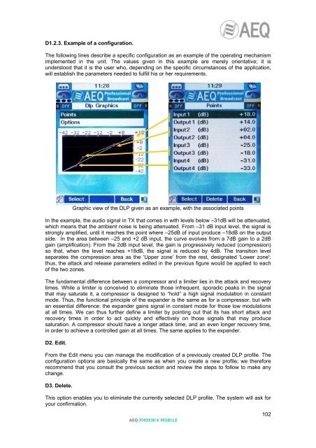
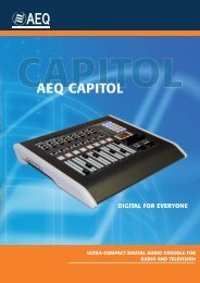
D1.2.3. Example of a configuration.The following lines describe a specific configuration as an example of the operating mechanismimplemented in the unit. The values given in this example are merely orientative; it isunderstood that it is the user who, depending on the specific circumstances of the application,will establish the parameters needed to fulfill his or her requirements.Graphic view of the DLP given as an example, with the associated pointsIn the example, the audio signal in TX that comes in with levels below –31dB will be attenuated,which means that the ambient noise is being attenuated. From –31 dB input level, the signal isstrongly amplified, until it reaches the point where –25dB of input produce –18dB on the outputside. In the area between –25 and +2 dB input, the curve evolves from a 7dB gain to a 2dBgain (amplification). From the 2dB input level, the gain is progressively reduced (compression)so that, when the level reaches +18dB, the signal is reduced by 4dB. The transition levelseparates the compression area as the ‘Upper zone’ from the rest, designated 'Lower zone';thus, the attack and release parameters edited in the previous figure would be applied to eachof the two zones.The fundamental difference between a compressor and a limiter lies in the attack and recoverytimes. While a limiter is conceived to eliminate those infrequent, sporadic peaks in the signalthat may saturate it, a compressor is designed to “hold” a high signal modulation in constantmode. Thus, the functional principle of the expander is the same as for a compressor, but withan essential difference: the expander gains signal in constant mode for those low modulationsat all times. We can thus further define a limiter by pointing out that its has short attack andrecovery times in order to act quickly and effectively on those signals that may producesaturation. A compressor should have a longer attack time, and an even longer recovery time,in order to achieve a controlled gain at all times. The same applies to the expander.D2. Edit.From the Edit menu you can manage the modification of a previously created DLP profile. Theconfiguration options are basically the same as when you create a new profile; we thereforerecommend that you consult the previous section and review the steps to follow to make anychange.D3. Delete.This option enables you to eliminate the currently selected DLP profile. The system will ask foryour confirmation.<strong>AEQ</strong> PHOENIX MOBILE102
ANNEXE E: Connect PHOENIX MOBILE into ISDN National-1.Practical notes for the configuration of the ISDN TERMINAL ADAPTER (TA) IN THE UNITEDSTATES AND OTHER COUNTRIES WITH NATIONAL 1 ISDN PROTOCOL:The ISDN (Integrated Services Digital Network) is a telephone connection system that permitsthe establishment of fully digital end-to-end communications. There are two types of ISDN links,depending on the number of 64 Kbps channels: Basic links (BRI – Basic Rate Interface) andPrimary links (PRI – Primary Rate Interface):- Basic links allow the simultaneous establishment of two connections or data channels,each with a capacity of 64Kbps.- Primary links allow 23 - 64 Kbps channels to be established in the USA, and 31 -64Kbps channels in Europe.To access ISDN services, you must subscribe to an ISDN phone line and connect equipment toit, such as an audio codec, that has an ISDN Terminal Adapter device to perform the tasks ofestablishing and maintaining connections through digital ISDN phone lines.The PHOENIX MOBILE has an ISDN Terminal Adapter for Basic links (BRI), which gives it acommunications capacity of two independent 64 Kbps data channels.We can find two types of physical connection to the ISDN: connection to a type U interface, andconnection to a type S/T interface:- The U interface connects the telephone exchange with the subscriber. It has two wires,the same as in conventional analog telephony, and only allows a point-to-pointconnection (a single device connected to the interface).- The S/T interface is obtained from the U interface, passing it through a NetworkTerminator (NT1) located at the subscriber’s premises. It has four wires and allows amultipoint connection of up to 7 devices.In the USA, phone companies do not supply the NT1, so the user is the one who must install it ifhe wants it. The most common situation is for there to be no NT1, and therefore access isthrough a U interface.In summary, in the USA, access via a U interface is most common, unless the subscriber hasasked the phone company to install an NT1 or has installed it himself (the NT1 is usually a boxattached to the wall, with a power supply, and some kind of light indicator, to which the two-wireexternal line enters and which has RJ-45 jacks).The PHOENIX’s universal TA (terminal adapter) allows both types of connections, and thus hastwo ISDN connectors, one RJ-45 (8 pins) for the S/T interface connection, and one RJ-11 (6pins) for the type U interface connection. The type of connection used must be configured in theunit’s setup.Although the ISDN is supposed to be a standard, differences can be found between theprotocols used by different countries. In the USA, there are several protocols that areincompatible with each other; fortunately, however, there is one protocol that is fairlystandardized (called National-1), which is usually available at all exchanges.The PHOENIX’s Universal Terminal Adapter can work with the NATIONAL-1 protocol (the mostwidely used in the USA). Selection of the desired protocol, in our case the NATIONAL-1, mustbe configured in the unit’s setup.In Europe and in other geographic areas, there is a protocol called EURO ISDN. There areminor differences between the EURO ISDN in different countries. These differences do notaffect the PHOENIX MOBILE.<strong>AEQ</strong> PHOENIX MOBILE103