Manual - AEQ International
Manual - AEQ International
Manual - AEQ International

You also want an ePaper? Increase the reach of your titles
YUMPU automatically turns print PDFs into web optimized ePapers that Google loves.
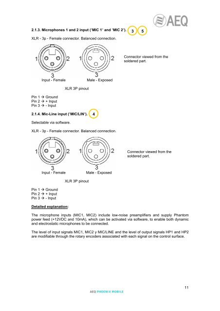
2.1.3. Microphones 1 and 2 input (“MIC 1“ and “MIC 2“).XLR - 3p - Female connector. Balanced connection.3 5Connector viewed from thesoldered part.Input - FemaleMale - ExposedXLR 3P pinoutPin 1 GroundPin 2 + InputPin 3 - Input2.1.4. Mic-Line input (“MIC/LIN“).4Selectable via software.XLR - 3p - Female connector. Balanced connection.Connector viewed from thesoldered part.Input - FemaleMale - ExposedXLR 3P pinoutPin 1 GroundPin 2 + InputPin 3 - InputDetailed explanation:The microphone inputs (MIC1, MIC2) include low-noise preamplifiers and supply Phantompower feed (+12VDC and 10mA), which can be activated via software, to enable both dynamicand electrostatic microphones to be connected.The level of input signals MIC1, MIC2 y MIC/LINE and the level of output signals HP1 and HP2are modifiable through the rotary encoders associated with each signal on the control surface.<strong>AEQ</strong> PHOENIX MOBILE11