- Page 2 and 3:
Table of ContentsFluorescent Electr
- Page 4 and 5:
Table of ContentsGlossarySection 8-
- Page 6 and 7:
Product OverviewRapid Start Ballast
- Page 8 and 9:
Application And Operating Informati
- Page 10 and 11:
Application And Operating Informati
- Page 12 and 13:
SpecificationsTYPICAL SPECIFICATION
- Page 14 and 15:
Fluorescent-ElectromagneticT8High O
- Page 16 and 17:
T12High Output LampsT8 U-Shaped Lam
- Page 18 and 19:
T12HOHigh Output Lamps• 800-840 m
- Page 20 and 21:
T12HO & VHOUNIVERSAL ®ELECTROMAGNE
- Page 22 and 23:
CIRCLINECircline Lamps• 430 mA•
- Page 24 and 25:
T12SLIMLINESlimline Lamps• 425-44
- Page 26 and 27:
PREHEAT/TRIGGERHigh Output Lamps•
- Page 28 and 29:
PREHEAT/TRIGGERUNIVERSAL ®ELECTROM
- Page 30 and 31:
EXPORTHigh Output LampsT8 U-Shaped
- Page 32 and 33:
EXPORTHigh Output LampsSlimline Lam
- Page 34 and 35:
EXPORTHigh Output LampsSlimline Lam
- Page 36 and 37:
ElectronicFluorescent BallastsA Com
- Page 38 and 39:
Product OverviewLow Power (L-A)The
- Page 40 and 41:
Application And Operating Informati
- Page 42 and 43:
SpecificationsTYPICAL SPECIFICATION
- Page 44 and 45:
SpecificationsTYPICAL SPECIFICATION
- Page 46 and 47:
SpecificationsTYPICAL SPECIFICATION
- Page 48 and 49:
SpecificationsTYPICAL SPECIFICATION
- Page 50:
TRIAD ® ELECTRONIC BALLASTSFOR (3)
- Page 53 and 54:
F17T8&F25T8TRIAD ® ELECTRONIC BALL
- Page 55 and 56:
F32T8• Low ProfileDesigns Feature
- Page 57 and 58:
F32T8• Low ProfileDesigns Feature
- Page 59 and 60:
F32T8ES30 WATT• High PerformanceM
- Page 61 and 62:
F32T8ES(25 WATT)• High Performanc
- Page 63 and 64:
F28T8TRIAD ® ELECTRONIC BALLASTSFO
- Page 65 and 66:
F32T8ES&F28T8TRIAD ® ELECTRONIC BA
- Page 67 and 68:
F40T8TRIAD ® ELECTRONIC BALLASTSFO
- Page 69 and 70:
T8HOHigh Output Lamps• Instant St
- Page 71 and 72:
T5• Multiple Lamp Operation• Ra
- Page 73 and 74:
T5&T5HOTRIAD ® T5 & T5HO ELECTRONI
- Page 75 and 76:
F40T12&F34T12EST12 Straight LampsT1
- Page 77 and 78:
T12SLIMLINESlimline Lamps• Standa
- Page 79 and 80:
T2• Programmed RapidStarting Opti
- Page 81 and 82:
Product OverviewDEMANDflex ® Balla
- Page 83 and 84:
DEMANDflexT8• Universal DCL ® Di
- Page 85 and 86:
DEMANDflexT5, T5HO & TT5• Univers
- Page 87 and 88:
DCL ControlsDCL CONTROLSMODELDESCri
- Page 89 and 90:
Product OverviewUniversal offers th
- Page 91 and 92:
NotesFluorescent DimmingPAGE 3-12FO
- Page 93 and 94:
Application And Operating Informati
- Page 95 and 96:
DaliPro ® PAGE 3- 16DaliPro ® DIM
- Page 97 and 98:
BALLASTAR0-10VDIMMINGT8 Straight La
- Page 99 and 100:
T8DIMMINGDIMENSIONS AND WIRING DIAG
- Page 101 and 102:
NotesFluorescent DimmingPAGE 3- 22
- Page 103 and 104:
Product OverviewElectronic Compact
- Page 105 and 106:
ConfigurationsStandard Side ExitBot
- Page 107 and 108:
SpecificationsTYPICAL SPECIFICATION
- Page 109 and 110:
TWINLAMPS5, 7, 9 & 11WATTSOR• Ope
- Page 111 and 112:
TWIN, QUAD& MULTIPLELAMPS18 WATTSOR
- Page 113 and 114:
MULTIPLELAMPS32, 42, 57 & 70 WATTS
- Page 115 and 116:
2DLAMPS10, 16 & 21WATTS• Ideal fo
- Page 117 and 118:
2DLAMPSMAGNETIC & ELECTRONIC COMPAC
- Page 119 and 120:
LONG TWINT5 LAMPS18, 24/27 WATTS•
- Page 121 and 122:
ELECTRONICLONG TWINT5 LAMPS50, 55 &
- Page 123 and 124:
LONG TWINT5 LAMPSMAGNETIC AND ELECT
- Page 125 and 126: NotesHIDPAGE 5-2FOR MORE INFORMATIO
- Page 127 and 128: Product OverviewFor maximum safety
- Page 129 and 130: NotesHIDPAGE 5-2FOR MORE INFORMATIO
- Page 131 and 132: Dry Capacitors (Cont.)90°C Rated 1
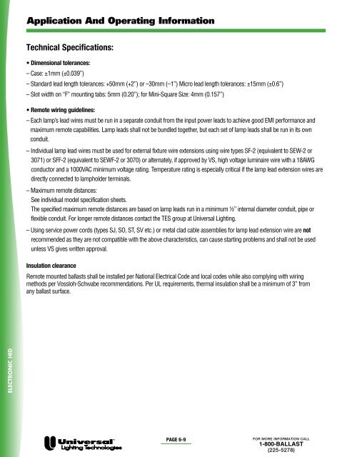
- Page 133 and 134: Application And Operating Informati
- Page 135 and 136: Application And Operating Informati
- Page 137 and 138: SpecificationsTYPICAL SPECIFICATION
- Page 139 and 140: Distributor Replacement KitsQuad, 4
- Page 141 and 142: Distributor Replacement KitsCanadia
- Page 143 and 144: MH250-400WATT• 60 Hz• Minimum s
- Page 145 and 146: MHHID CORE & COIL BALLASTSMETAL HAL
- Page 147 and 148: PULSE STARTMH150-200 WATT• 60 Hz
- Page 156 and 157: HID CORE & COIL BALLASTSHIGH PRESSU
- Page 158 and 159: HID CORE & COIL BALLASTSHIGH PRESSU
- Page 160 and 161: HID CORE & COIL BALLASTS50 HERTZ50
- Page 162 and 163: F-CAN BALLASTSHIGH PRESSUE SODIUM
- Page 164 and 165: STANDARD IGNITORS • INSTANT RESTR
- Page 166 and 167: 0.750"g2.500"1.250"Starter Referenc
- Page 168 and 169: eHIDLess energy. Enhanced performan
- Page 170 and 171: eHID Product FamilyOrder code Part
- Page 172 and 173: WiringDimming Ballasts4aWIRING (For
- Page 174 and 175: Dimensions13 1492.0/3.6292.0/3.6246
- Page 178 and 179: Application And Operating Informati
- Page 180 and 181: Sign IlluminatingBallastsA Complete
- Page 182 and 183: Sign Ballast Footage ChartNo. ofLam
- Page 184 and 185: UNIVERSAL ®MAX-3HIGH OUTPUTSIGN BA
- Page 186 and 187: GlossaryAC (Alternating Current)-Cu
- Page 188 and 189: IndexCatalog # Page # Catalog # Pag
- Page 190 and 191: IndexCatalog # Page # Catalog # Pag
- Page 192 and 193: IndexCatalog # Page # Catalog # Pag
- Page 194 and 195: Limited WarrantyUniversal Lighting


