triad® electronic ballasts - Conserve-A-Watt Lighting, Inc
triad® electronic ballasts - Conserve-A-Watt Lighting, Inc
triad® electronic ballasts - Conserve-A-Watt Lighting, Inc

You also want an ePaper? Increase the reach of your titles
YUMPU automatically turns print PDFs into web optimized ePapers that Google loves.
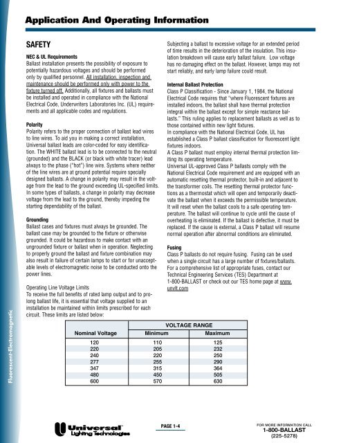
Application And Operating InformationFluorescent-ElectromagneticSAFETYNEC & UL RequirementsBallast installation presents the possibility of exposure topotentially hazardous voltages and should be performedonly by qualified personnel. All installation, inspection andmaintenance should be performed only with power to thefixture turned off. Additionally, all fixtures and <strong>ballasts</strong> mustbe installed and operated in compliance with the NationalElectrical Code, Underwriters Laboratories <strong>Inc</strong>. (UL) requirementsand all applicable codes and regulations.PolarityPolarity refers to the proper connection of ballast lead wiresto line wires. To aid you in making a correct installation,Universal ballast leads are color-coded for easy identification.The WHITE ballast lead is to be connected to the neutral(grounded) and the BLACK (or black with white tracer) leadalways to the phase (“hot”) line wire. Systems where neitherof the line wires are at ground potential require speciallydesigned <strong>ballasts</strong>. A change in polarity may result in the voltagefrom the lead to the ground exceeding UL-specified limits.In some types of <strong>ballasts</strong>, a change in polarity may decreasevoltage from the lead to the ground, thereby impeding thestarting dependability of the ballast.GroundingBallast cases and fixtures must always be grounded. Theballast case may be grounded to the fixture or otherwisegrounded. It could be hazardous to make contact with anungrounded fixture or ballast when in operation. Neglectingto properly ground the ballast and fixture combination mayalso result in failure of certain lamps to start or for unacceptablelevels of electromagnetic noise to be conducted onto thepower lines.Operating Line Voltage LimitsTo receive the full benefits of rated lamp output and to prolongballast life, it is essential that voltage supplied to aninstallation be maintained within limits prescribed for eachcircuit. These limits are listed below:Subjecting a ballast to excessive voltage for an extended periodof time results in the deterioration of the insulation. This insulationbreakdown will cause early ballast failure. Low voltagehas no damaging effect on the ballast. However, lamps may notstart reliably, and early lamp failure could result.Internal Ballast ProtectionClass P Classification - Since January 1, 1984, the NationalElectrical Code requires that “where Fluorescent fixtures areinstalled indoors, the ballast shall have thermal protectionintegral within the ballast except for simple reactance <strong>ballasts</strong>.”This ruling applies to replacement <strong>ballasts</strong> as well as tothose contained within new light fixtures.In compliance with the National Electrical Code, UL hasestablished a Class P ballast classification for fluorescent lightfixtures indoors.A Class P ballast must employ internal thermal protection limitingits operating temperature.Universal UL-approved Class P <strong>ballasts</strong> comply with theNational Electrical Code requirement and are equipped with anautomatic resetting thermal protector, built-in and adjacent tothe transformer coils. The resetting thermal protector functionsas a thermostat which will open and temporarily deactivatethe ballast when it exceeds the permissible temperature.It will reset when the ballast cools to a safe operating temperature.The ballast will continue to cycle until the cause ofoverheating is eliminated. If the ballast is defective, it must bereplaced. If the cause is external, a Class P ballast will resumenormal operation after abnormal conditions are eliminated.FusingClass P <strong>ballasts</strong> do not require fusing. Fusing can be usedwhen a single circuit has a large number of fixtures/<strong>ballasts</strong>.For a comprehensive list of appropriate fuses, contact ourTechnical Engineering Services (TES) Department at1-800-BALLAST or check out our TES home page at www.unvlt.comVOLTAGE RANGENominal Voltage Minimum Maximum120 110 125220 205 232240 220 250277 255 290347 315 364480 450 505600 570 630PAGE 1-4FOR MORE INFORMATION CALL1-800-BALLAST(225-5278)