

COMPUTING
Second Edition - Orchard Publications
Second Edition - Orchard Publications
- No tags were found...

You also want an ePaper? Increase the reach of your titles
YUMPU automatically turns print PDFs into web optimized ePapers that Google loves.
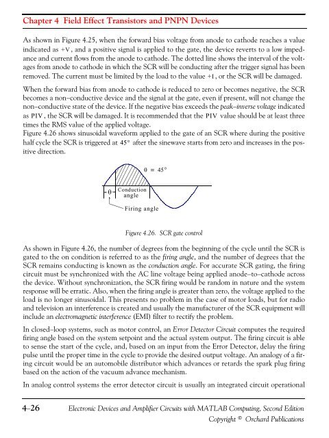
Chapter 4 Field Effect Transistors and PNPN DevicesAs shown in Figure 4.25, when the forward bias voltage from anode to cathode reaches a valueindicated as +V , and a positive signal is applied to the gate, the device reverts to a low impedanceand current flows from the anode to cathode. The dotted line shows the interval of the voltagesfrom anode to cathode in which the SCR will be conducting after the trigger signal has beenremoved. The current must be limited by the load to the value +I , or the SCR will be damaged.When the forward bias from anode to cathode is reduced to zero or becomes negative, the SCRbecomes a non−conductive device and the signal at the gate, even if present, will not change thenon−conductive state of the device. If the negative bias exceeds the peak−inverse voltage indicatedas PIV, the SCR will be damaged. It is recommended that the PIV value should be at least threetimes the RMS value of the applied voltage.Figure 4.26 shows sinusoidal waveform applied to the gate of an SCR where during the positivehalf cycle the SCR is triggered at 45° after the sinewave starts from zero and increases in the positivedirection.θ = 45°θConductionangleFiring angleFigure 4.26. SCR gate controlAs shown in Figure 4.26, the number of degrees from the beginning of the cycle until the SCR isgated to the on condition is referred to as the firing angle, and the number of degrees that theSCR remains conducting is known as the conduction angle. For accurate SCR gating, the firingcircuit must be synchronized with the AC line voltage being applied anode−to−cathode acrossthe device. Without synchronization, the SCR firing would be random in nature and the systemresponse will be erratic. Also, when the firing angle is greater than zero, the voltage applied to theload is no longer sinusoidal. This presents no problem in the case of motor loads, but for radioand television an interference is created and usually the manufacturer of the SCR equipment willinclude an electromagnetic interference (EMI) filter to rectify the problem.In closed−loop systems, such as motor control, an Error Detector Circuit computes the requiredfiring angle based on the system setpoint and the actual system output. The firing circuit is ableto sense the start of the cycle, and, based on an input from the Error Detector, delay the firingpulse until the proper time in the cycle to provide the desired output voltage. An analogy of a firingcircuit would be an automobile distributor which advances or retards the spark plug firingbased on the action of the vacuum advance mechanism.In analog control systems the error detector circuit is usually an integrated circuit operational4−26Electronic Devices and Amplifier Circuits with MATLAB Computing, Second EditionCopyright © Orchard Publications


