

COMPUTING
Second Edition - Orchard Publications
Second Edition - Orchard Publications
- No tags were found...

You also want an ePaper? Increase the reach of your titles
YUMPU automatically turns print PDFs into web optimized ePapers that Google loves.
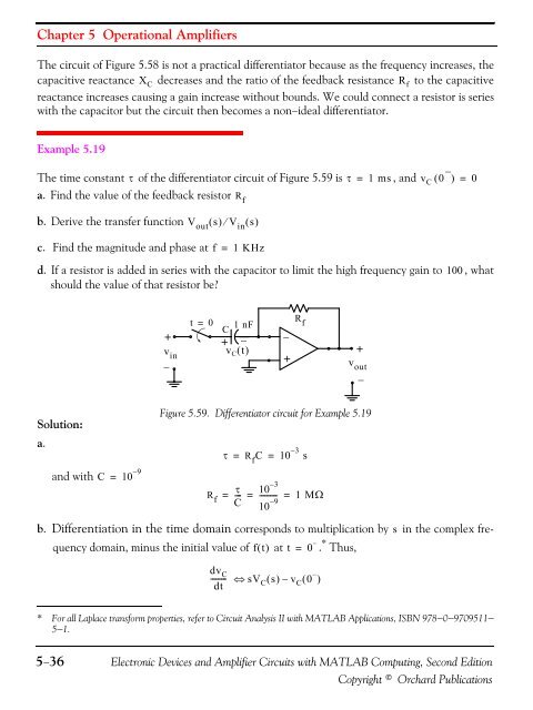
Chapter 5 Operational AmplifiersThe circuit of Figure 5.58 is not a practical differentiator because as the frequency increases, thecapacitive reactance X C decreases and the ratio of the feedback resistance R f to the capacitivereactance increases causing a gain increase without bounds. We could connect a resistor is serieswith the capacitor but the circuit then becomes a non−ideal differentiator.Example 5.19The time constant τ of the differentiator circuit of Figure 5.59 is τ = 1 ms, and v C ( 0 − ) = 0a. Find the value of the feedback resistorb. Derive the transfer function V out ( s) ⁄ V in ( s)R fc. Find the magnitude and phase atf=1 KHzd. If a resistor is added in series with the capacitor to limit the high frequency gain to 100 , whatshould the value of that resistor be?t = 0+v in−1 nFC+ −v C () t−+R f+v out−Solution:a.and withC = 10 – 9Figure 5.59. Differentiator circuit for Example 5.19R fτ = R f C = 10 – 3 s10 – 3τ= --- = --------- = 1 M ΩC 10 – 9b. Differentiation in the time domain corresponds to multiplication by s in the complex frequencydomain, minus the initial value of ft () at t = 0 −. * Thus,dv-------- C⇔ sVdt C ( s) – v C ( 0 −)* For all Laplace transform properties, refer to Circuit Analysis II with MATLAB Applications, ISBN 978−0−9709511−5−1.5−36Electronic Devices and Amplifier Circuits with MATLAB Computing, Second EditionCopyright © Orchard Publications


