

COMPUTING
Second Edition - Orchard Publications
Second Edition - Orchard Publications
- No tags were found...

You also want an ePaper? Increase the reach of your titles
YUMPU automatically turns print PDFs into web optimized ePapers that Google loves.
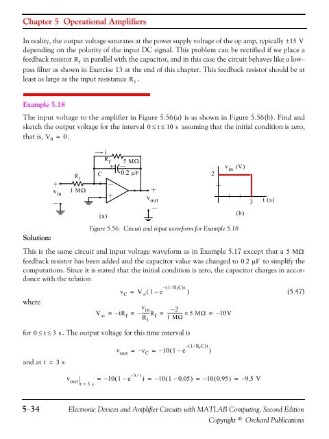
Chapter 5 Operational AmplifiersIn reality, the output voltage saturates at the power supply voltage of the op amp, typically ±15 Vdepending on the polarity of the input DC signal. This problem can be rectified if we place afeedback resistor in parallel with the capacitor, and in this case the circuit behaves like a low−pass filter as shown in Exercise 13 at the end of this chapter. This feedback resistor should be atleast as large as the input resistance .R fR 10 t 10 sExample 5.18The input voltage to the amplifier in Figure 5.56(a) is as shown in Figure 5.56(b). Find andsketch the output voltage for the interval ≤ ≤ assuming that the initial condition is zero,that is, V 0 = 0 .R 1CiR f5 MΩ0.2 μF2v in ( V)v in1 MΩv out3t ( s)( a)( b)Solution:Figure 5.56. Circuit and input waveform for Example 5.18This is the same circuit and input voltage waveform as in Example 5.17 except that a 5 MΩfeedback resistor has been added and the capacitor value was changed to 0.2 μF to simplify thecomputations. Since it is stated that the initial condition is zero, the capacitor charges in accordancewith the relationwherefor0≤t≤3 sV ∞–(v C V ∞ 1 e 1 ⁄ R f C )t= ( – )v in –2= – iR f = –------RR f = ------------- × 5 MΩ = – 10V1 1 MΩ. The output voltage for this time interval is(5.47)v out–(– 10 1 e 1 ⁄ R f C )t= = – ( – )v Cand at t=3 sv out = – 10( 1 – e – 3 ⁄ 1 ) = – 10( 1 – 0.05)= – 10( 0.95)= – 9.5 Vt = 3 s5−34Electronic Devices and Amplifier Circuits with MATLAB Computing, Second EditionCopyright © Orchard Publications


